Tekmar D528 Manuale utente

tekmarNet®2 Thermostat 528
Installation & Operation Manual
D528
12/11
Zoning
Replaces:08/10
1 of 24 © 2011 D 528 - 12/11
The tekmarNet®2 Thermostat 528
provides operation for:
One Stage Heat•
Introduction
Features
Zone Synchronization
Zone Post Purge
Intelligent Setback (Timer 033)
One touch overrides (User Switch)
Auto Heating Cycle
tN2 Communication compatible
Room temperature limiting
Requires 2 Wires
Pulse Width Modulation
CSA C US Approved for use in
USA and Canada
Outdoor Temperature Display
Air Group Member
Backlight
Freeze Protection
Equipment Exercising
Floor Warming (Slab Sensor 079)
1 Auxiliary Sensor input
Supports Radiant Floor Cooling
•
•
•
•
•
•
•
•
•
•
•
•
•
•
•
•
•
•
Note
tN2 Zone Manager, Expansion
Module, Wiring Center or House
Control required for operation
tN2 Zone Manager, Expansion
Module, Wiring Center or House
Control required for operation
•
•

2 of 24© 2011 D 528 - 12/11
Congratulations on the purchase of your new tekmar thermostat.
This manual will step through the complete installation, programming and sequence
of operation for this control. At the back, there are tips for control and system
troubleshooting.
Getting Started
Preparation
tekmar or jeweller screwdriver
Phillips head screwdriver
•
•
Wire Stripper•
Tools Required
------------------------------------------------------
------------------------------------------------------
Materials Required
--------------------------------------------------
--------------------------------------------------
2, #6 x 1” Wood Screws
18 AWG LVT Solid Wire
(Low Voltage Connections)
•
•
Optional Adapter Plate 007 (for
installation on 2” x 4” gang box)
•
Installation
Table of Contents
Getting Started ..............................2
Installation .........................................2
Caution..........................................2
Preparation....................................2
Removing The Thermostat Base...3
Mounting The Thermostat Base....3
Thermostat Wiring.........................4
Testing the Thermostat Wiring ......5
Mounting the Thermostat ..............5
Cleaning the Thermostat...............6
Switch Settings ..................................6
User Interface....................................7
Display...........................................7
Button Operation ...........................7
Symbols Description .....................7
Settings ....................................8-14
Sequence of Operation....................15
Heating Operation .......................15
Air Group Operation ....................16
Floor Cooling...............................16
Schedules ................................... 17
Scenes (System Override) ..........17
Troubleshooting ...............................18
Error Messages......................18-21
Frequently Asked Questions .......22
Job Record..................................23
Technical Data.............................23
Limited Warranty and Product
Return Procedure ........................24
Caution
Improper installation and operation of this control could result in damage to the
equipment and possibly even personal injury or death. It is your responsibility
to ensure that this control is safely installed according to all applicable codes and
standards. This electronic control is not intended for use as a primary limit control.
Other controls that are intended and certified as safety limits must be placed into
the control circuit.

3 of 24 © 2011 D 528 - 12/11
Choose the placement of the thermostats early in the construction process to
enable proper wiring during rough-in.
Consider the following:
Interior Wall.
Keep dry. Avoid potential leakage onto the control.
Relative Humidity max 80% up to 88°F (31°C) decreasing linearly to 50% RH
at 104°F (40°C). Non-condensing environment.
No exposure to extreme temperatures beyond 32-122°F (0-50°C).
No draft, direct sun, or other cause for inaccurate temperature readings.
Away from equipment, appliances, or other sources of electrical interference.
Easy access for wiring, viewing, and adjusting the display screen.
Approximately 5 feet (1.5 m) off the finished floor.
The maximum length of wire is 1000 feet (300 m).
Strip wire to 3/8” (10 mm) for all terminal connections.
Use standard 18 AWG wire for the tN2 connections.
•
•
•
•
•
•
•
•
•
•
•
Installation Location
-------------------------------------------------
-------------------------------------------------
Removing The Thermostat Base
Push
tab
1Remove thermostat
from base
2
To remove the thermostat base:
Place a small slot screwdriver or similar
tool into the slot located on the top of
the thermostat.
While pushing down against the plastic
tab, pull the thermostat away from the
thermostat’s base.
•
•
Mounting The Thermostat Base
Stud
Switch
Box
Thermostat
Base
007 Adaptor
Plate
31/4”
(83 mm)
If a single gang switch box is used,
an Adaptor Plate 007 is required to
mount the thermostat to the box.
Fasten the base of the
thermostat to the adaptor plate.
Feed the wiring through the
openings in the back of the
adaptor plate and thermostat.
Use the upper and lower screw
holes to fasten the adaptor plate
to the box.
•
•
•
Mounted on switch box

4 of 24© 2011 D 528 - 12/11
If a switch box was not used, mount the
thermostat directly to the wall.
Feed the wiring through the openings in
the back of the thermostat.
Use screws in the screw holes to fasten the
thermostat to the wall. At least one of the
screws should enter a wall stud or similar
rigid material.
•
•
Stud
23/8”
(60 mm)
screwhole
23/8”
(60 mm)
screwhole
Thermostat
Base
Wall
Mounted on wallboard
Thermostat Wiring
The thermostat operates a single heating system zone.
Power and communication are provided to the thermostat by connecting the tN2
terminals on the thermostat to the tN2 terminals on a tN2 Wiring Center, House Control,
Zone Manager or Expansion Module. tN2 terminals are not polarity sensitive.
Connect the optional auxiliary sensor wires to the sensor terminals 3 and 4.
12 34
tN2 Manager, Module
or Wiring Center
tN2 tN2 Slab Sensor 079, or
Outdoor Sensor 070, or
Indoor Sensor 076, 077, 084
1234
tNt 528
528
One Stage Heat
Mmm YYYY
Lot # 12345
Meets Class B:
Canadian ICES
FCC Part 15
1023-02
tN2
1
tN2
2
Switch Settings:
For instructions see brochure
Use at least 65°C conductors
ON
Sensor
34
Setback
Scene
Lock
Not used Not used
Unlock
Off
Off
No Power

5 of 24 © 2011 D 528 - 12/11
Testing the Thermostat Wiring
Testing the Power
---------------------------------------------------
---------------------------------------------------
If the thermostat display turns on, this indicates that the thermostat is operating
correctly and there are no electrical issues. In the event that the display is off, or
the display is cycling on and off:
1. Remove the tN2 wires from the thermostat.
2. Use an electrical meter to measure DC voltage between the tN2 terminals.
If the DC voltage is 0 V (dc) for 20 seconds, then there is an open or short circuit
in the tN2 wires.
If the DC voltage is 0 V (dc) for 10 seconds and then is 23 to 24 V (dc) for 5
seconds, this indicates the wiring is correct.
3. Connect the thermostat to the tN2 wires connected to a zone on a House Control,
Wiring Center, or Zone Manager.
4. If the thermostat display is off, or is cycling on and off, move the thermostat to the
next available zone on the House Control, Wiring Center, or Zone Manager.
If the thermostat display remains permanently on, there may be a fault with the
previously tried zone on the House Control, Wiring Center, or Zone Manager.
If the thermostat display continues to be off, or is cycling on and off, there may
be a fault on the thermostat.
If a fault is suspected, contact your tekmar sales representative for assistance.
Testing the Heat Zone Output
----------------------------------------
----------------------------------------
1. Press the button and set the heating temperature above the current room
temperature. Make sure the display does not show “WWSD” or “Floor Max”.
2. When the H1 symbol appears on the display, use an electrical meter to check
for voltage on the House Control, Wiring Center, or Zone Manager relay. The
voltage is 24 V (ac) for zone valves, and 120 V (ac) for zone pumps when
operating correctly.
•
•
•
•
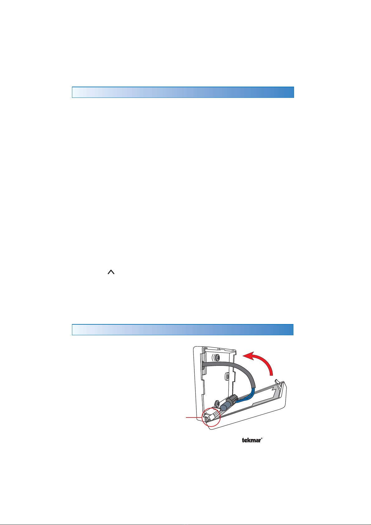
Mounting the Thermostat
To place the thermostat back on the
mounting base:
Place thermostat bottom tabs on
matching mounting base notches.
Pivot top of the thermostat
towards wall, ensuring wires clear
obstructions.
The top clasp makes a clicking
sound when properly closed.
•
•
•
Pivot
Tab

6 of 24© 2011 D 528 - 12/11
Switch Settings
Switches are set to “On”
position from the factory, and
do not require changing for
most applications.
12 34
1234
tNt 528
528
One Stage Heat
Mmm YYYY
Lot # 12345
Meets Class B:
Canadian ICES
FCC Part 15
1023-02
tN2
1
tN2
2
Switch Settings:
For instructions see brochure
Use at least 65°C conductors
ON
Sensor
34
Setback
Scene
Lock
Not used Not used
Unlock
Off
Off
No Power
Switch
Position
Action
1
ON
SETBACK
The thermostat follows a programmable setback schedule
as a schedule member if available. Requires the installation
of a Timer 033 to use this feature.
OFF
OFF
The thermostat does not follow a programmable setback
schedule.
2
ON
SCENE
The thermostat responds to changes in the scene (system
wide manual overrides). Requires the installation of a User
Switch 479 to use this feature.
OFF OFF
The thermostat does not respond to scenes.
3
ON
LOCK ACCESS LEVEL
Locked to ‘User’ access level. Set to Lock when installation
completed.
OFF
UNLOCK ACCESS LEVEL
Unlock to allow ‘User’ and “Installer’ access level. Set to
Unlock during installation process.
tekmarNet®reset control must also be set to Unlocked
(Installer access level).
4
ON Not used
OFF Not used
The thermostats’s exterior can be cleaned using a damp cloth. Moisten the cloth
with water and wring out prior to wiping the control. Do not use solvents or cleaning
solutions.
Cleaning the Thermostat
12 34
1234
Mmm YYY
Meets Class B:
Canadian ICES
Switch Settings:
ON
Setback
Scene
Lock
Not used Not used
Unlock
Off
Off

7 of 24 © 2011 D 528 - 12/11
SECONDARY DISPLAYMAIN DISPLAY
HEAT
Heat is turned on.
SUN
Operating at the occupied
(day) temperature.
MOON
Operating at the unoccupied
(night) temperature.
AWAY
Operating at the Away scene
temperature.
AIR GROUP
The air group is cooling.
Heating can start once the
cooling is finished.
LOCK
Locked to ‘User’ access level.
CLOCK
Operating on a
programmable schedule.
tekmarNet®
Communication is present.
WARNING SYMBOL
Indicates an error is present.
WARM WEATHER SHUT
DOWN
The heating system has been
shut off for the summer.
Display
Symbols Description
User Interface
Button Operation
Press the or the button to select the room temperature.

8 of 24© 2011 D 528 - 12/11
Settings (1 of 7)
Display Range Access Description Set to
40 to 95°F
(4.5 to 35.0°C)
Default = 70°F
(21.0°C)
Installer
User
SET ROOM HEAT
Set the room heating temperature while in the
event.
40 to 95°F
(4.5 to 35.0°C)
Default = 65°F
(18.5°C)
Installer
User
SET ROOM HEAT
Set the room heating temperature while in the
event.
40 to 95°F
(4.5 to 35.0°C)
Default = 62°F
(16.5°C)
Installer
SET ROOM HEAT AWAY
Set the room heating temperature while in the Away
scene.
Continued on next page.
• Press and hold down both the and buttons for 2 seconds to change from one step to the next.
• Release both buttons once the step has been reached.
• Press the or the button to change the setting, if available.
• Press and hold down both the and buttons for 2 seconds to go to the next step, OR
• After 10 seconds of no button activity, the display goes back to normal operation.
• Note: Set switch setting #3 and tekmarNet®system control to Unlock to change Access level to Installer.
Press
+
Together

9 of 24 © 2011 D 528 - 12/11
Settings (2 of 7)
Display Range Access Description Set to
40 to 122°F
(4.5 to 50.0°C)
Default = 72°F
(22.0°C)
Installer
User
SET FLOOR HEAT
Set the floor heating temperature while in the
event.
Available when:
A slab sensor is installed on the auxiliary sensor
input AND Sensor setting in the Adjust menu is set
to Floor AND Room Sensor setting in the Adjust
menu is set to Off.
•
40 to 122°F
(4.5 to 50.0°C)
Default = 65°F
(18.5°C)
Installer
User
SET FLOOR HEAT
Set the floor heating temperature while in the
event.
Available when:
A slab sensor is installed on the auxiliary sensor
input AND Sensor setting in the Adjust menu is set
to Floor AND Room Sensor setting in the Adjust
menu is set to Off.
•
Off, 30 sec, On,
On +
Default = 30 sec
Installer
User
BACKLIGHT
Select the backlight operation.
Off = Permanently Off
30 = Temporary on for 30 seconds
On = Permanently On
On + = On during and off during
Continued on next page.

10 of 24© 2011 D 528 - 12/11
Display Range Access Description Set to
°F or °C
Default = °F
Installer
User
TEMPERATURE UNITS
Press the or the button to change from °F to
°C and vice versa.
Device Type with
Software Version,
Address
Installer
User
DEVICE TYPE
Display alternates between the Device Type (large
number) with Software Version (upper right corner)
and the thermostat address.
40 to 95°F
(4.5 to 35.0°C)
Default = 85°F
(29.5°C)
Installer
MAXIMUM SET ROOM HEAT
Set the maximum room heating limit while in the
event.
40 to 95°F
(4.5 to 35.0°C)
Default = 85°F
(29.5°C)
Installer
MAXIMUM SET ROOM HEAT
Set the maximum room heating limit while in the
event.
40 to 95°F
(4.5 to 35.0°C)
Default = 45°F
(7.0°C)
Installer MINIMUM SET ROOM HEAT
Set the minimum room heating limit.
Settings (3 of 7)
Continued on next page.
Indice
Altri manuali Tekmar Termostato

Tekmar
Tekmar tekmarNet 557 Manuale utente

Tekmar
Tekmar 543 Manuale utente

Tekmar
Tekmar 537 Manuale utente

Tekmar
Tekmar 562 Manuale utente

Tekmar
Tekmar D 508 Manuale utente

Tekmar
Tekmar tekmarNet2 Thermostat 530 Manuale utente

Tekmar
Tekmar 518 Manuale utente

Tekmar
Tekmar tekmarNet 552 Manuale utente

Tekmar
Tekmar 540 Manuale utente

Tekmar
Tekmar tekmarNet 4 Manuale utente

Tekmar
Tekmar 518 Manuale utente

Tekmar
Tekmar 507 Manuale utente

Tekmar
Tekmar 521 Manuale utente

Tekmar
Tekmar 538 Manuale utente

Tekmar
Tekmar 519 Manuale utente

Tekmar
Tekmar 528 Manuale utente

Tekmar
Tekmar D 054 Manuale utente

Tekmar
Tekmar tNt 540 Manuale utente

Tekmar
Tekmar 538 Manuale utente

Tekmar
Tekmar tekmarNet 4 538 Manuale utente