Teleflex TFXIDD Manuale utente

TFXIDD
In-Dash
Digital Depth Gauge
operations manual

Warning! This device should not be used as
a navigational aid to prevent collision,
grounding, boat damage or personal injury.
When the boat is moving, water depth may
change too quickly to allow time for you to
react. Always operate the boat at very slow
speeds if you suspect shallow water or
submerged objects.

Section 1: GENERAL INFORMATION . . . . . . . . . . . . . . . 2
How Sonar Works. . . . . . . . . . . . . . . . . . . . . . . . . 2
Section 2: USING THE DIGITAL DEPTH GAUGE . . . . . . . 4
What you see on-screen . . . . . . . . . . . . . . . . . . . . 4
Control functions . . . . . . . . . . . . . . . . . . . . . . . . . 4
Shallow Alarm . . . . . . . . . . . . . . . . . . . . . . . . . . . 5
Deep Alarm . . . . . . . . . . . . . . . . . . . . . . . . . . . . . 6
Units . . . . . . . . . . . . . . . . . . . . . . . . . . . . . . . . 7
Keel Offset . . . . . . . . . . . . . . . . . . . . . . . . . . . . . 7
Section 3: MAINTENANCE . . . . . . . . . . . . . . . . . . . . . . 9
Maintenance . . . . . . . . . . . . . . . . . . . . . . . . . . . . 9
Troubleshooting . . . . . . . . . . . . . . . . . . . . . . . . . 10
Specifications . . . . . . . . . . . . . . . . . . . . . . . . . . 12
TABLE OF CONTENTS
REV 10201E
2
GENERAL INFORMATION
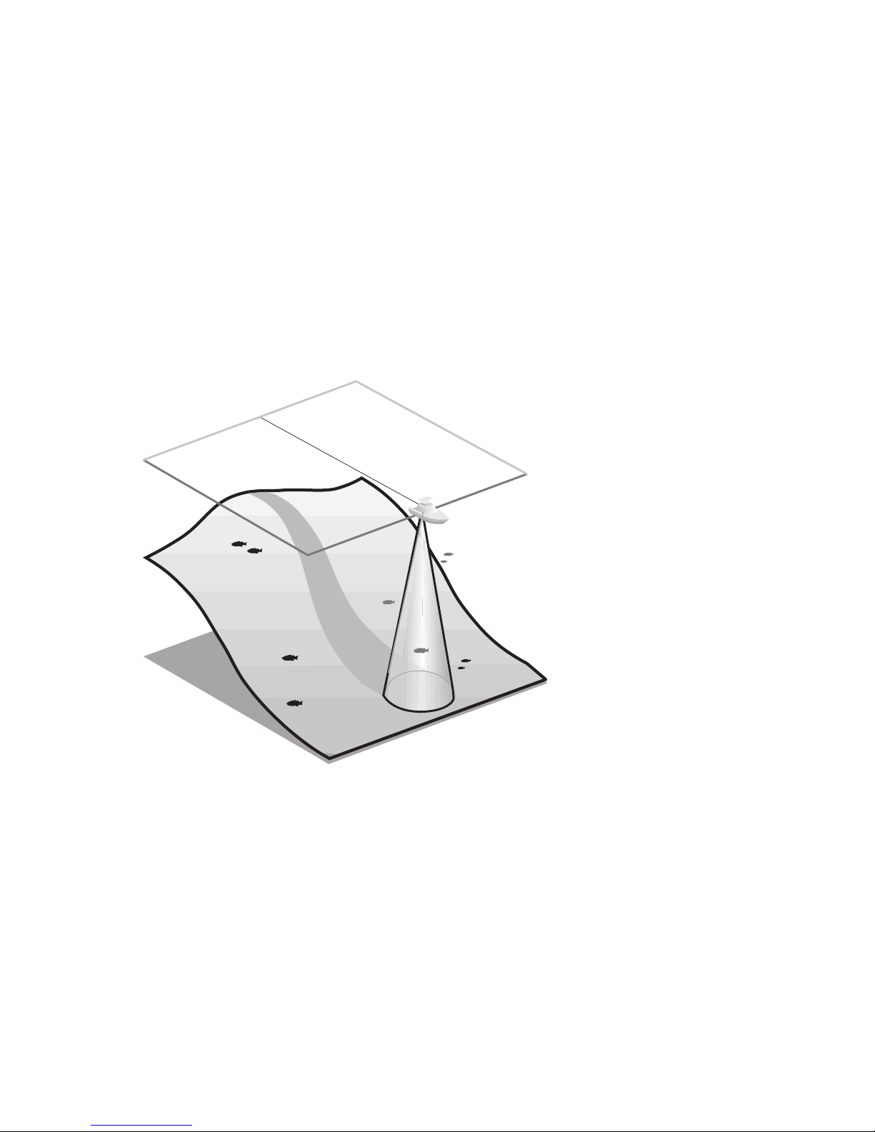
HOW SONAR WORKS
HOW SONAR WORKS
Sonar uses sound waves to determine the
presence and location of underwater objects.
The time measured between the transmission of
the sound wave, and the reception of any
reflection can be used to determine distance.
Analysis of the reflected signal can also
be use to determine location, size,
composition, etc.
Digital depth
gauges consist of
two primary com-
ponents: the sonar
unit and the
transducer. The
sonar unit contains
the transmitter
and receiver, as
well as the user
controls and display.
The transducer is mounted
beneath the water surface and
converts electrical energy from the trans-
mitter into mechanical pulses or sound waves.
The transducer also receives the reflected sound
waves and converts them back into electrical
signals for display on the sonar unit.

3
The transmit and receive cycle is very fast. A
sound wave can travel from the surface to a
depth of 240' and back again in less than ¹⁄₄ of
a second; so it is unlikely that your boat can
“outrun” this sonar signal.
As the digital depth gauge transducer receives
sonar signals, it converts them to a digital
depth that is displayed on your digital depth
gauge. The depth reading is continuously
updated as you travel across the water.
Easy-to-use controls on the digital depth gauge
allow you to set the SHALLOW ALARM or DEEP
ALARM for an audible alert when the boat is in
extreme shallow or deep water.
The liquid crystal display (LCD) offers sharp
viewing, even in bright direct sunlight, and is
continuously lit for nighttime operation.
NOTE: Actual depth capability depends on such
factors as bottom hardness, water conditions, and
transducer installation. Units will typically read to
deeper depths in fresh water than in salt water.
GENERAL INFORMATION
HOW SONAR WORKS

4
USING THE DIGITAL DEPTH GAUGE
WHAT YOU SEE ON-SCREEN
WHAT YOU SEE ON-SCREEN
The digital depth gauge uses a backlit 7-
segment display in conjunction with a 3-button
keypad to control all user functions. At initial
power-up, the unit will begin normal operation
and display the digital depth and the units of
measure. Figure 1 shows a typical view you
might see on-screen at initial power-up.
CONTROL FUNCTIONS
The digital depth gauge uses 3 buttons to
control the Shallow Alarm, Deep Alarm, Keel
Offset, and Units of Measure function. While in
normal operation, pressing the SET button
selects a Function and blinks its corresponding
indicator on the display. Once a Function has
been selected it may be adjusted by pressing
the UP and Down arrow buttons to adjust the
setting. Further presses of the SET button will
sequentially select the other functions for
adjustment. All user settings are remembered
by the digital depth gauge, even when
powered off.
When in an active function, a single press to an
arrow button will result in a single incremental
adjustment. Pressing and holding an arrow
button will sequence through a range of
adjustments. If no adjustment is made for 5
seconds, the unit will return to normal
operation.
Figure 1
5
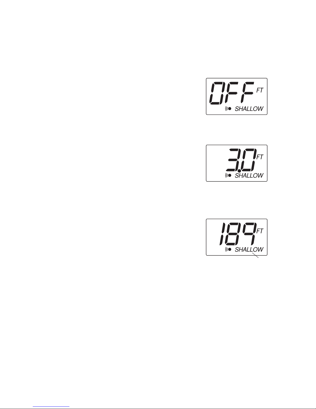
Shallow Alarm
The SHALLOW ALARM function can be set for
depths ranging from 1 to 20 feet and sounds an
alarm when the depth is less than the setting.
From normal operation, pressing SET once will
display the SHALLOW ALARM setting and blink
the “SHALLOW”icon. The UP ARROW will
activate the SHALLOW ALARM and also
increase the selected value. The DOWN ARROW
will reduce the value. Hold the UP ARROW
until you reach the desired depth setting.
Note: The maximum SHALLOW ALARM
setting can not meet or exceed the current
DEEP ALARM setting.
After your selection is made, the unit will return
to normal operation after 5 seconds. The
“SHALLOW”icon should now be visible
(Figure 4).
If the depth of the water is less than the selected
value, the alarm will sound and the “SHALLOW”
icon will blink to indicate the alarm. Pressing any
button will mute the alarm; pressing SET will
mute the alarm and activate the SHALLOW
ALARM function for additional adjustment. To
permanently turn the alarm off, use the DOWN
ARROW to return the display to “OFF”.
USING THE DIGITAL DEPTH GAUGE
CONTROL FUNCTIONS
Figure 3
“SHALLOW” icon
Figure 4
Figure 2

6
USING THE DIGITAL DEPTH GAUGE
CONTROL FUNCTIONS
Deep Alarm
The DEEP ALARM can be set for depths up to 99
feet and sounds an alarm when the depth is
greater than the setting.
Press SET until the DEEP ALARM function
becomes active. This is indicated by the blinking
“DEEP”icon. The UP ARROW will activate the
DEEP ALARM and also increase the selected
value. The DOWN ARROW will reduce the value.
Continue to press and hold the UP ARROW until
you reach your desired value.
Note: The minimum DEEP ALARM setting
can not meet or go below the current
SHALLOW ALARM setting.
After your selection is made, the unit will return
to normal operation after 5 seconds. The
“DEEP”icon should now be visible (Figure 6).
If the depth of the water is greater than the
selected value, the alarm will sound and the
icon will blink to indicate the alarm. Pressing
any button will mute the alarm; pressing SET
will mute the alarm and activate the DEEP
ALARM function for additional adjustment. To
permanently turn the alarm off, use the DOWN
ARROW to return the display to “OFF”.
Figure 5
Figure 6
“DEEP”icon

7
Units
The UNITS Control Function selects the UNITS of
measure for depth readout and alarm functions.
The three settings available are Feet, Meters or
Fathoms.
Press SET until the UNITS function is activated
on-screen. This is indicated by the blinking
UNITS icon. Pressing either arrow will allow you
to select from the choices. Continue to press an
arrow until the desired readout is selected: FT
for feet, M for meters, FA for fathoms.
After your selection is made, the unit will return
to normal operation after 5 seconds. The
selected units icon should now be visible as
shown in Figure 8.
Keel Offset
The Keel Offset function adjusts the digital depth
readout to display depth readings from either the
waterline or the keel (lowest point) of the boat,
instead of from the location of the transducer
which is usually somewhere in between. This
permits optimum transducer location and depth
readouts suited to your needs.
To determine the value to enter into the Keel
Offset setting, first decide whether depth from
the waterline or depth from the keel is desired.
Measurements will need to be made for the
location desired.
USING THE DIGITAL DEPTH GAUGE
CONTROL FUNCTIONS
Figure 8
Selected units icon
Figure 7
Figure 9
Negative Keel Offset

8
For depth from the keel of the boat, accurately
measure the vertical distance between the face of
the transducer and keel of the boat. This
measurement will then be entered into the Keel
Offset function as a negative (-) number. (Figure 9)
For depth measurements from the waterline,
accurately measure the vertical distance
between the face of the transducer and the
waterline of the boat. This measurement will
then be entered into the Keel Offset function as
a positive (+) number. (Figure 10)
To enable Keel Offset press SET until the KO icon
is displayed on the screen. The default setting of
the unit is off which is displayed as zero. From
the default setting of 0.0, use the DOWN arrow
to enter the negative (-) number to set the unit
for depth from the keel. Or, from the default
setting of 0.0, use the UP arrow to enter a
positive (+) number to set the unit for depth
from the waterline.
The available settings are +10 to -10 feet. After
your selection is made, the unit will return to
normal operation after 5 seconds. The “KO”icon
should now be visible as shown in figure 13.
Figures 11,12 and 13 depict a scenario where
the KEEL OFFSET has been set to -2 feet. Figure
13 shows the return to normal operation with
the updated depth readout.
Figure 10
Positive Keel Offset
Figure 12
Figure 13
Keel Offset icon
Figure 11
USING THE DIGITAL DEPTH GAUGE
CONTROL FUNCTIONS
Indice


