
Temptek PTK Series Manuale utente

TEMPTEK, INC.
525 East Stop 18 Road Greenwood, IN 46142
317-887-6352 fax: 317-881-1277
Service Department fax: 317-885-8683
www.Temptek.com
E-mail: [email protected]
I.O.M. #129 updated 09/30/2019
INSTRUCTION MANUAL • INSTALLATION • OPERATION • MAINTENANCE
Model:
Serial Number :

INSTRUCTION MANUAL
TOUGH TANK ‘PPT’
for TOWER WATER SYSTEMS
and CHILLED WATER SYSTEMS
With Checkmate Controller
COVERING
INSTALLATION
OPERATION
MAINTENANCE
TEMPTEK, INC.
525 East Stop 18 Road Greenwood, IN 46142
317-887-0729 fax: 317-881-1277
Service Department fax: 317-885-8683
www.Temptek.com
E-mail: [email protected]

Page: 3
TEMPTEK, INC.
525 East Stop 18 Road Greenwood, Indiana 46142
317-887-6352 Fax: 317-881-1277
Email: [email protected]
PTK Series Polyethylene Pump Tank Station with Checkmate Control System
TABLE OF CONTENTS
1.0 GENERAL 4
1.1 Safety 5
1.2 Efciency 5
1.3 Component Placement 5
2.0 INSTALLATION 7
2.1 Installation Drawings 8
2.2 Pump Base To Tank Mating Instructions 8
2.3 Plant Water Distribution 8
2.4 Water Treatment 8
2.5 Vacuum Breakers 9
2.6 Process Connections 9
2.7 Water Supply Connection 10
2.8 DrainAndOverowConnections 10
2.9 Electrical Connection 10
2.10 Probe Installation 11
3.0 OPERATIONS 12
3.1 General 13
3.2 Start Up/Operations Procedure 13
3.3 Instrument And Controls 16
4.0 MAINTENANCE 19
4.1 Preventive Maintenance 19
4.2 Pump Seal Service 20
4.3 Solenoid Valve Service 23
4.4 Instrument Calibration 24
5.0 ELECTRICAL
5.1 Electrical 26
6.0 APPENDIX 27
6.1 Typical Press Drop 28
6.2 Checkmate Second Set Point Guide 29

PTK Series Polyethylene Pump Tank Station with Checkmate Control System
Page: 4
TEMPTEK, INC.
525 East Stop 18 Road Greenwood, Indiana 46142
317-887-6352 Fax: 317-881-1277
Email: [email protected]
1.0 GENERAL
1.1 Safety
1.2 Efciency
1.3 Component Placement

Page: 5
TEMPTEK, INC.
525 East Stop 18 Road Greenwood, Indiana 46142
317-887-6352 Fax: 317-881-1277
Email: [email protected]
PTK Series Polyethylene Pump Tank Station with Checkmate Control System
1.1 SAFETY
A. It is important to become thoroughly familiar with this manual and the operating
characteristic of the equipment.
B. Several important references are made to safety considerations in this manual. It is the
owner’sresponsibilitytoassureproperoperatortraining,installation,operation,and
maintenance of the equipment.
C. Observe all warning and safety placards applied to the unit. Failure to observe warnings
can result in serious injury or death.
1.2 EFFICIENCY
A. Longtermefciencyofoperationislargelydeterminedbypropermaintenanceofthe
mechanical parts of the unit and the water quality.
B. TheFactoryacceptsnoresponsibilityforinefcientoperationordamagecausedby
improperinstallationoftheunitorforeignmaterialsintheprocessuid.
C. A water treatment system must be part of any pump tank system installation. The
servicesofaprofessionalqualiedwatertreatmentcompanyisrequiredtopreventscale,
corrosion, bacterial and biological growth.
The Factory highly recommends the services of a competent water treatment specialist
be obtained and his recommendations be followed. The Factory accepts no responsibility
forinefcientoperation,ordamagecausedbyforeignmaterialsorfailuretouseadequate
water treatment.
1.3 COMPONENT PLACEMENT
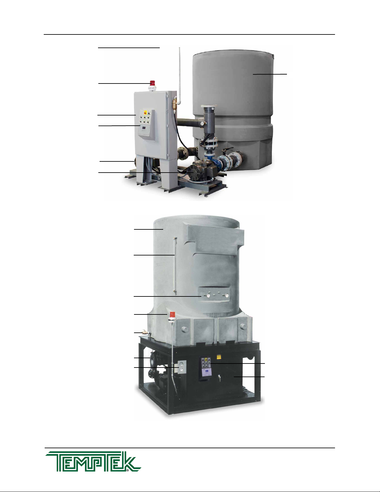
A. The TTK polyethylene pump tank station is designed to circulate temperature stabilized
uidthroughtheprocessresultinginprocesstemperaturecontrol.
B. Theabilityoftheequipmenttodothisissignicantlyaffectedbythemethodof
installation. The picture on the following page will give the reader an overview to the
major components of the unit.
C. If any questions arise, please contact The Factory Sales Representative or Service
Department.
D. TTKpumptanksystemsaredesignedforaspecicduty.Thecongurationofyour
system may differ from those in this manual. Contact the factory for additional
informationaboutyourspecicsystem.
PTK Series Polyethylene Pump Tank Station with Checkmate Control System
Page: 6
TEMPTEK, INC.
525 East Stop 18 Road Greenwood, Indiana 46142
317-887-6352 Fax: 317-881-1277
Email: [email protected]
Service Lid
Alarm
Process Pump
Tower/Evaporator Pump
CheckmateTM Control Panel
Polyethylene Reservoir
Control Console
Polyethylene Tank
Sight Glass
Temperature Gauges
Alarm Beacon
Drain Valve
Pump Assembly
Pressure Gauges
Electrical Cabinet
CheckmateTM Control Panel

Page: 7
TEMPTEK, INC.
525 East Stop 18 Road Greenwood, Indiana 46142
317-887-6352 Fax: 317-881-1277
Email: [email protected]
PTK Series Polyethylene Pump Tank Station with Checkmate Control System
2.0 INSTALLATION
2.1 Installation Drawings
2.2 Pump Base To Tank Mating Instructions
2.3 Plant Water Distribution
2.4 Water Treatment
2.5 Vacuum Breakers
2.6 Process Connections
2.7 Water Supply Connection
2.8 DrainAndOverowConnection
2.9 Electrical Connection
2.10 Probe Installation

PTK Series Polyethylene Pump Tank Station with Checkmate Control System
Page: 8
TEMPTEK, INC.
525 East Stop 18 Road Greenwood, Indiana 46142
317-887-6352 Fax: 317-881-1277
Email: [email protected]
2.1 INSTALLATION DRAWINGS
A. A number of typical drawings have been provided within this manual and with the unit. It
is necessary to review all drawings supplied to assure proper installation.
B. Contactthefactoryfortheelectricaldiagramthatisspecictoyourunit.
C. You will need the unit serial number when contacting the factory.
2.2 PUMP BASE TO TANK MATING INSTRUCTIONS
A. The following instructions detail the mating of the pump base to the polyethylene tank.
Refer to the drawing on the next page.
B. Unless otherwise noted, all necessary parts have been supplied by the factory.
C. Optional standby pump, alarm automatic water make-up and control console are shown
in the drawing. Not all systems are supplied with these options.
D. Pleasenotethatthecontrolconsoleisshown‘offbase’fordrawingpurpose’sonly.
E. Pump discharge manifold and sight glass are not shown in the drawing.
F. Mate the pump base to the tank.
2.3 PLANT WATER DISTRIBUTION
A. Please note that all material used in the installation should be rated for 150°F and 200 psi
minimum. Also note that the materials should have the equivalent diameter or larger of
their process connections.
B. Plant water distribution system design is critical to maximum performance of the system.
Careful attention should be paid to the pipe sizing, length of runs, number of elbows, tees
andvalving,asspecied.Normally,themostsuccessfulinstallationsarethosewhich
insuremaximumowsandminimumpressuredrops.
C. All water distribution piping should be properly braced to prevent sway and undue stress.
Brace all pipes to assure no excess loads or strains are applied to the unit. Insulate all
pipes to control excessive condensation and to help maintain set temperature to the
process (on chilled water systems).
2.4 WATER TREATMENT
A. A water treatment system must be part of any cooling tower or chilled water
system installation. The services of a professional qualied water treatment
company is required. A water treatment system typically consists of a plan to
control scaling, corrosion and biological growth. Failure to control the quality of
the water can result in premature unit failure, fouling of plant wide heat transfer
surfaces and biological growth that can cause sickness and even death.
B. Keeping the water in a cooling tower or chilled water system clean has benet
by reducing scale and fouling and ensuring that the cooling process is operating
Page: 9
TEMPTEK, INC.
525 East Stop 18 Road Greenwood, Indiana 46142
317-887-6352 Fax: 317-881-1277
Email: [email protected]
PTK Series Polyethylene Pump Tank Station with Checkmate Control System
efciently. Fouling can lead to a loss of plant performance.
C. The Manufacturer assumes no responsibility for equipment failures or other results from
untreated or improperly treated water.
D. Legionella. Cooling towers must be treated for and protected from Legionella. Follow
ASHRAE Standard 188P and/or CTI Guidelines WTB-14B, and /or OSHA Guidelines
Section III Chapter 7 and/or the recommendation of your professional water treatment
expert to prevent Legionella in your tower. Failure to prevent Legionella may result in
sickness or death.
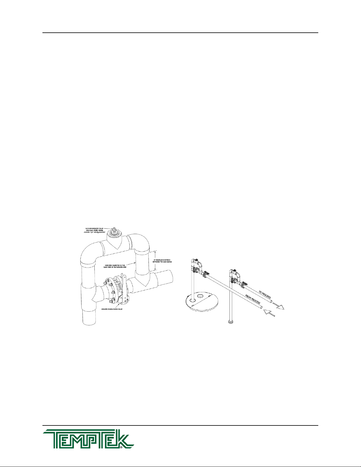
2.5 VACUUM BREAKERS
A. Vacuum breakers are required in all systems where overhead piping is used. Vacuum
breakerskeepthemainheadersystemfullofuidandpreventtankoverowduringshut
down periods.
B. The purpose of the vacuum breaker/anti-siphon (also called a drain-back dam) is to retain
water in the header system during shut-down periods and to allow for air purge which
eliminates shock to plumbing during start-up.
C. Itisnecessarytoinstallvacuumbreakersinthe‘supply’and‘return’lines.Thevacuum
breaker must be installed at the highest point in the system, nearest to the tanks to
bemosteffective.Anipplelengthof8inchesminimumisrequiredtocreatesufcient
vacuum to open the Cash Acme model VR-801.
2.6 PROCESS CONNECTIONS
A. Connect equipment process pump discharge port to main header supply line.
B. Connect equipment chiller or tower pump discharge port to chiller to tower cell inlet.
C. Install return line from the chiller or tower cell into the back 1/3 section of the cold tank
throughtheprovideopening.Returnlinefromtowerisgravityinducedowandslopingof
thispipeiscriticaltoproperowrates(minimum10%slope).
Typical Vacuum Breaker System

PTK Series Polyethylene Pump Tank Station with Checkmate Control System
Page: 10
TEMPTEK, INC.
525 East Stop 18 Road Greenwood, Indiana 46142
317-887-6352 Fax: 317-881-1277
Email: [email protected]
D. Install‘fromprocess”lineintotheback1/3sectionofthehotsideofthetankthroughthe
provided opening.
E. Note: all lines returning to the tank should extend below the water level, approximately
1.5 feet from the bottom of the tank.
F. Note: on a single pump system, the return line will connect directly to the chiller or tower
cell inlet. The line exiting out of the chiller or tower cell should be installed into the back
1/3 section of the cold side of the tank through the provided opening.
2.7 WATER MAKE-UP SUPPLY CONNECTION
A. Connecttheunit’s‘WATERSUPPLY’porttotheplant’scitywaterorwellwatersupply.
B. The factory recommend minimum operating water supply pressure requirement is
identiedontheunit’sdatapate.Thisisnormally20psi.
C. For units with electric automatic water make-up the water supply connection is located on
the reservoir. The make-up solenoid valve provides the water supply connection.
D. For units with mechanical automatic water make-up the water supply connection is
locatedonthereservoir.Abulk-headttingattachedtoaoatvalvelocatedinsidethe
tank provides the water supply connection.
E. Localcodesnormallyrequireabackowpreventiondevicebeinstalledinthewater
make-up line (customer supplied).
2.8 DRAIN AND OVERFLOW CONNECTIONS
A. Connectthedrainandoverowportstotheplant’sdrainagesystem.Thisisnormallya
sanitary sewer. Consult local codes.
2.9 ELECTRICAL CONNECTION
A. Electricalpowersupplyrequirementsareidentiedontheequipmentdataplate.
B. VERIFYTHATTHEAVAILABLEVOLTAGESUPPLYISTHESAMEASTHEUNIT’S
VOLTAGE REQUIREMENTS.
WARNING:Donotconnecttheunittoavoltagesupplysourcenotequaltotheunit’s
voltagerequirementsasspeciedontheunit’sdataplate.Useofincorrectvoltagewill
voidtheunit’swarrantyandcauseasignicanthazardthatmayresultinseriouspersonal
injury and unit damage.
C. For units with the optional central control console... a customer supplied four conductor
cable is required for connection to a customer supplied fused disconnecting means. The
fuseddisconnectingmeansshallbesizedandinstalledaccordingtotheunit’spower
supply requirements and local electrical codes. Connect the power cable to the terminal
L-1,L-2,L-3andthegroundlug(seegure2.9A).Somemodelsmayrequireapower
supply entry hole be made in the electrical cabinet.
D. For units without the optional central control console separate high voltage power with
customer supplied disconnecting means is required at each motor starter. Select a four
Indice
Manuali Sistema idrico popolari di altre marche

Spirotech
Spirotech SPIROVENT SUPERIOR S250 Manuale utente

Culligan
Culligan Aqua-Cleer Aqua-Cleer Advanced Drinking Water... Manuale utente

A.O. Smith
A.O. Smith Dura-Max AJH - 1000A - P Manuale utente

Microline
Microline T.F.C.-4 Manuale

Eureka Forbes
Eureka Forbes Aquaguard Select Manuale utente

Cetetherm
Cetetherm AquaEfficiency Manuale utente


