
THE SHOWER LAB VIEW 19F Manuale utente
04/2021 V 1.0
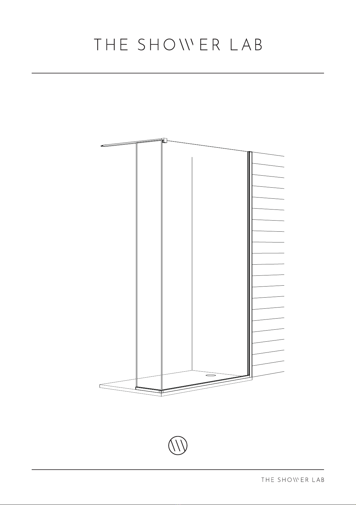
VIEW 19F Illustration - View 19F
SB1 Stay Bar

04/2021 V 1.0
VIEW 19F
IMPORTANT
•This shower screen / enclosure must be installed by suitably qualified individuals. We
recommend a minimum of two people for safe assembly of certain sections of this screen.
•Ensure all appropriate safety equipment, especially protective footwear, safety glasses
and gloves are used.
•When drilling holes in ceramic tiles, use masking tape to prevent the drill from slipping:
DO NOT use hammer action as this will crack the tiles. Use a high quality drill bit to ensure
a clean, precise hole.
Tighten hinges and brackets to the recommended 15.6N.
•
•
Please leave these instructions with the customer following installation.
PRIOR TO INSTALLATION
•Before disposing of the packaging and prior to commencing assembly, please check all
the components to ensure that they have been supplied correctly and are undamaged.
Subsequent claims for missing or damaged pieces will not be accepted once the
packaging has been disposed of and installation commenced.
•In the event of any queries please contact your supplier quoting the relevant model
information.
•The Tray / Tiled floor on which this screen is to be installed must be level on all sides.
•It may be necessary to use alternate fixings to those supplied, depending on the properties
of the walls to be fixed to.
•Use the protective corners supplied at all times until the glass is moved to its final position.
•Ensure that the glass is installed correctly, taking care to avoid installing the glass upside
down. On certain panels an easy clean coating is applied to one side only, this is clearly
marked with a sticker on the non-coated side. The coated surface is to be fitted inwards
towards the inside (wet side) of the screen.
•Ensure that all surfaces to be sealed are clean and dry prior to applying the silicone
sealant. Use a high grade fungal resistant sealant.
•Allow a minimum of 24 hours after application of the silicone sealant prior to using the
screen.
TOOLS & MATERIALS REQUIRED
Junior Hacksaw
Straight Edge (Steel
Rule)
Fine Tooth File
Set or Roofing
Square
Masking Tape
Modelling Knife
Spirit Level
Pencil
Silicone Gun
Power Drill
Ø6mm Masonry Drill Bit
2x Suction Glass Lifters
High Quality Silicone Sealant
Tape Measure
Pozi-drive
Screwdrivers, PZ1&2
Safety Glasses and
Gloves
CARE AND MAINTENANCE
(please ensure that these instructions are left with the installed unit)
•We recommend routine cleaning of your screen / enclosure with hot water using a soft
cloth, then drying with a dry soft cloth or chamois leather.
Ritec Aftercare for Shower Glass is recomended for best results.
•All glass has been treated with EASY CLEAN glass finish and care must be taken to avoid
any abrasive cleaning products that may damage the special surface protection.
•DO NOT use acidic based de-scaler products or products containing bleaches or solvents.
Digital Torque Wrench
04/2021 V 1.0
VIEW 19F
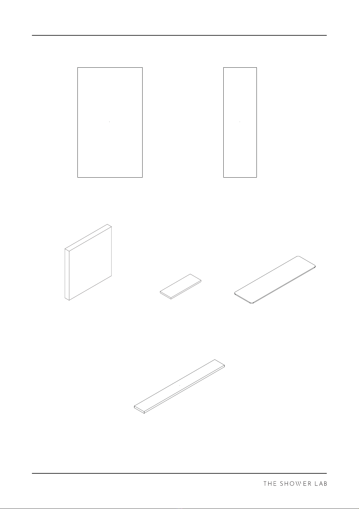
Glass Panel
x1
Nylon Block
x1
Supplied Parts
Return Panel
x1
Spacers Packers
Glass to Glass Adhesive Gasket
x1
04/2021 V 1.0
VIEW 19F
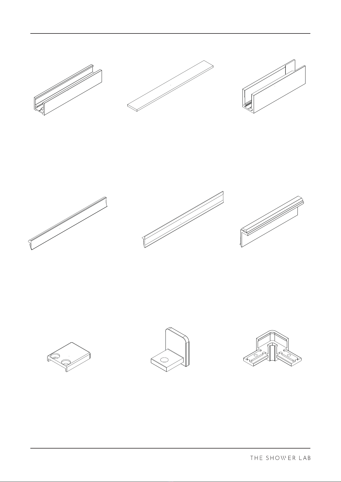
Underframe Wedge Gasket
x2
Underframe
x2
Underframe Gasket
x2
Wall Prole
x1
Wall Prole Soft Seal
x1
Wall Prole Rigid Seal
x1
Supplied Parts
Underframe End Cap
x1
Wall Prole End Cap
x1
Underframe 90°Connector
x1
04/2021 V 1.0
VIEW 19F
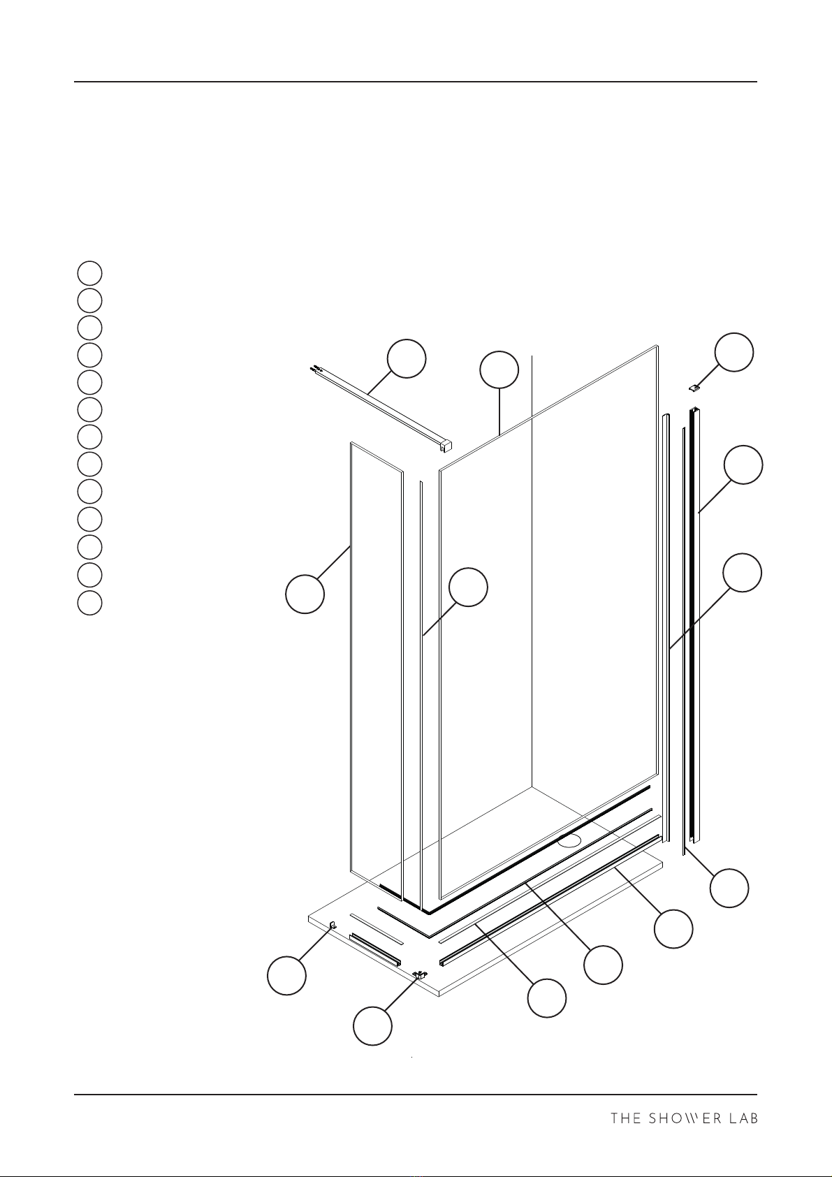
These instructions are for the View 19F. An SB1 Stay Bar is used for this illustration.
The following instructions are valid for both the 20mm and 30mm proles. The 30mm prole is
used in the following instructions.
Please use the below diagram to reference the list of parts.
A
B
I
C
H
D
F
E
G
Inline Panel
Return Panel
Wall Prole
Wall Prole Rigid Seal
Wall Prole Soft Seal
Underframe
Underframe Connector
Underframe Wedge Gasket
JUnderframe Gasket
Wall Prole End Cap
KUnderframe End Cap
LGlass Adhesive Tape
MStaybar (SB1 Shown)
A
B
D
C
G
I
J
H
E
K
M
LF
04/2021 V 1.0
VIEW 19F
01/14
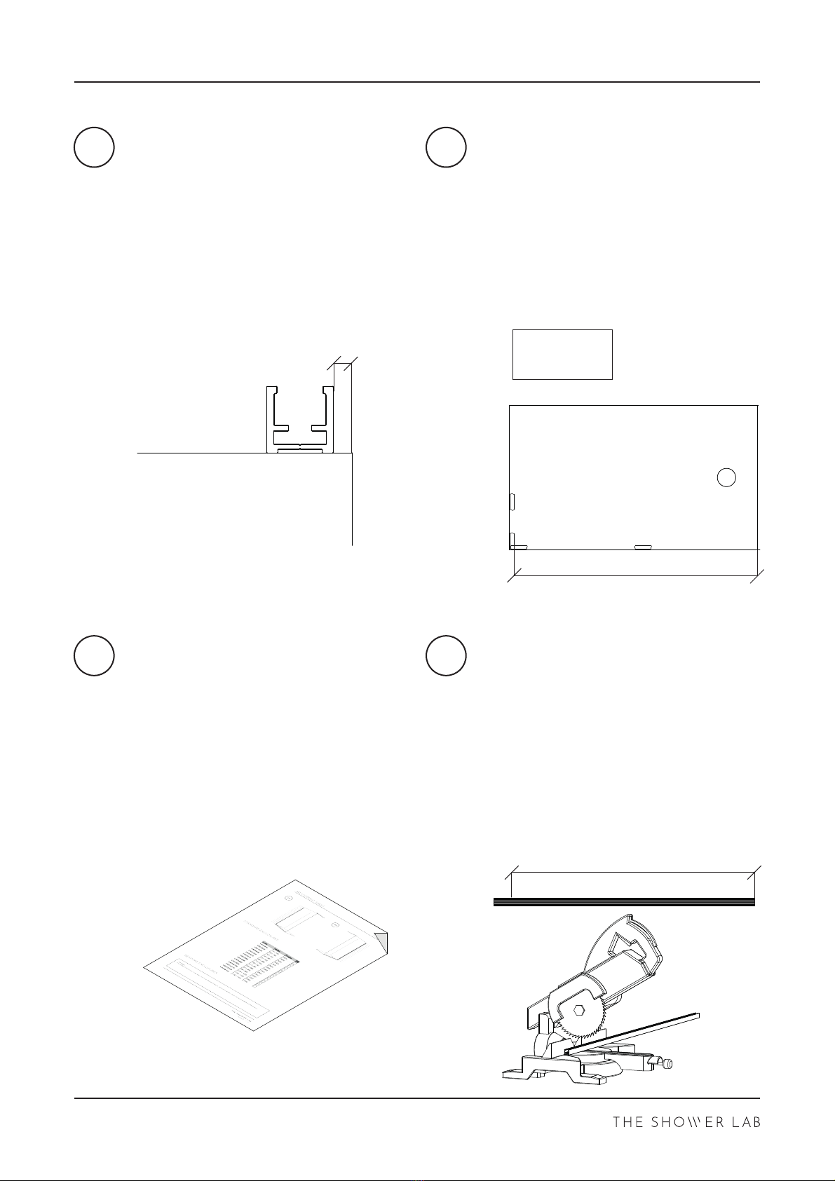
Posion the Underframe parallel to
tray edge. If using a raised shower tray,
leave a minimum 3mm gap from the
edge of the tray (5mm is
recommended).
Use tape to mark this dimension.
Repeat for the Return Underframe
Profile.
Measure the distance from the tape
edge to the ling and take note of this
distance.
F =
Check the dimensions are within the
allowed adjustments by referencing the
aached adjustment sheet.
Subtract 22mm from the Front
Underframe dimension. This is the
profile width. Mark this measurement
on the Front Underframe.
Cut squarely using a chop saw.
Use a fine toothed file to remove any
burrs, be careful not to damage the
surface finish.
3mm minimum
Shower Tray
x - 22mm
F
01 02
03 04
04/2021 V 1.0
VIEW 19F
02/14
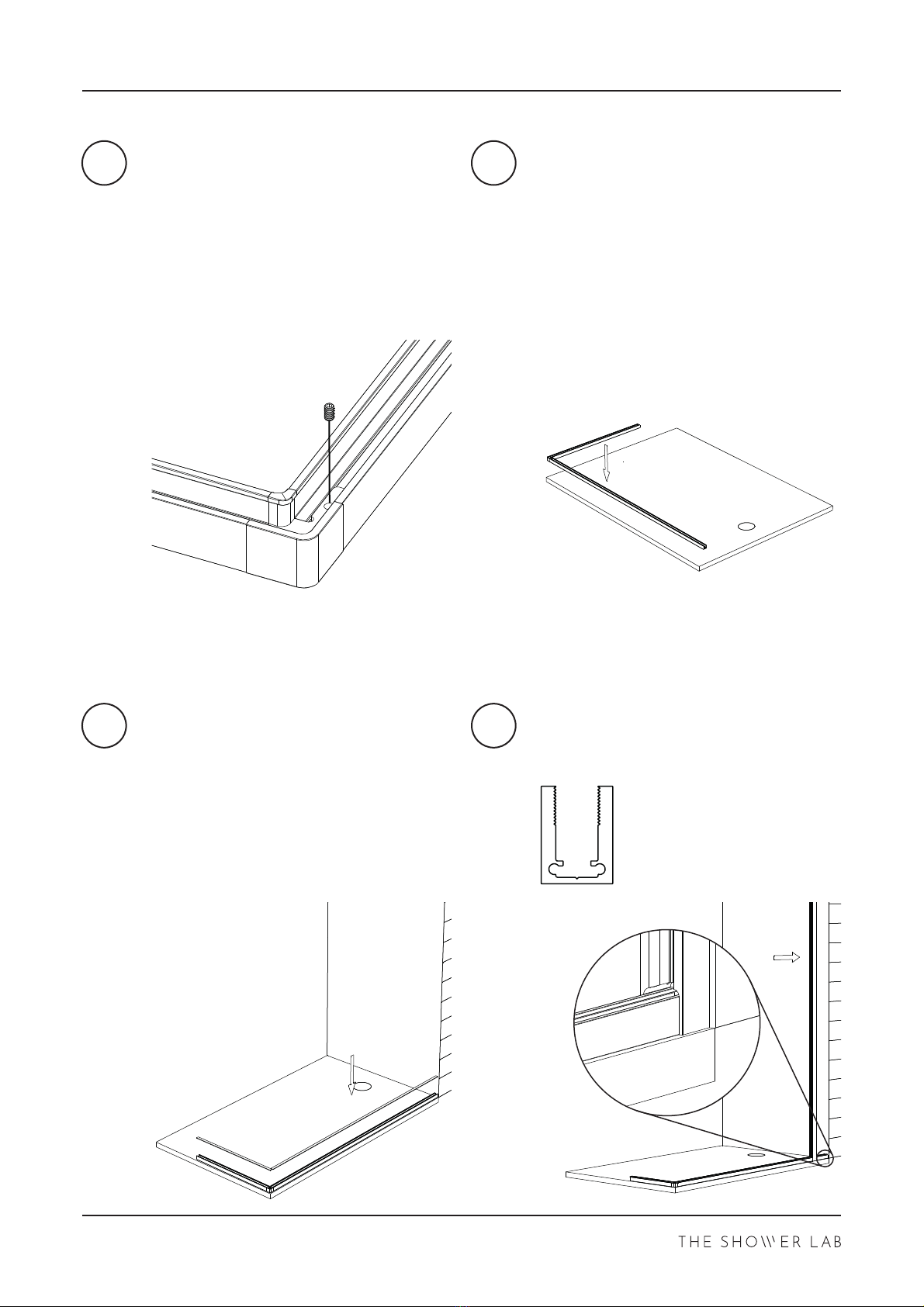
Connect the Underframe Profiles
together using the Underframe 90°
Connector and supplied screws.
Temporarily fix the Underframe into
the correct posion using double sided
tape. Push firmly into posion and
ensure that the Underframe is firmly
against the wall where the channel will
be fixed to.
DO NOT use the exisng tape. This tape
is for final posioning of Underframe.
Place the Underframe Gaskets where
the glass will sit into the Underframe
and bu up against the wall.
Place the Wall Profile over the
Underframe and up against the wall.
05 06
07 08
04/2021 V 1.0
VIEW 19F
03/14
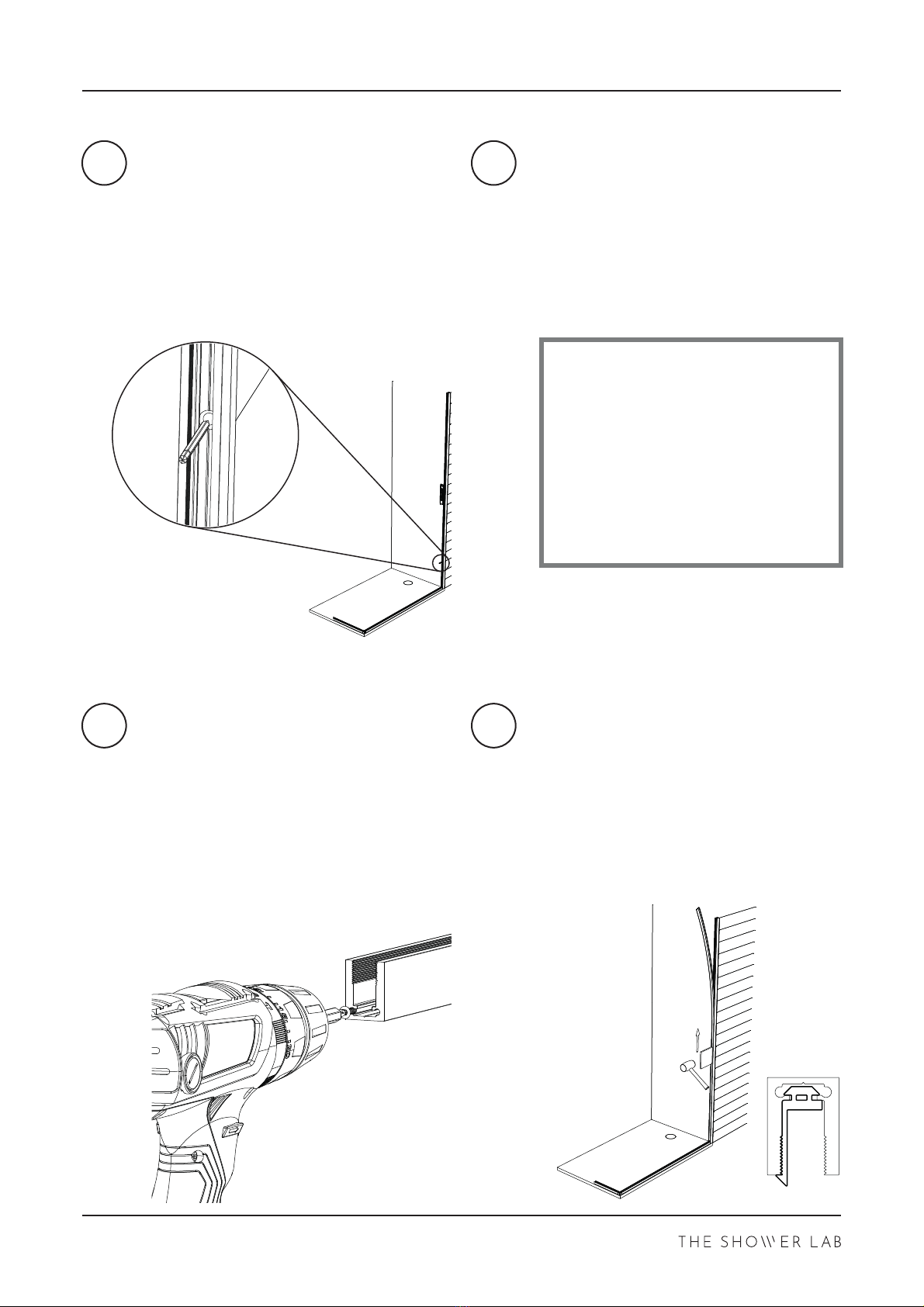
Ensure the Wall Profile is vercal by
using a spirit level. Mark the posions
of the pre-drilled holes.
Remove the Wall Profile and drill holes
with a 6mm high quality drill bit for a
clean and precise hole.
Fully insert the wall plugs.
Pre drill the screws in to the Wall
Profile to create the thread to ease
later steps.
Remove screws aer drilling.
Fix the Wall Profile in place.
Take the Wall Profile So Seal and push
the seal into place on the Wall Profile
to cover the screws.
Ensure the fin is on the inside (wet
side).
Use the Nylon Block to help.
Wet Side
Professional Tip
If drilling ceramic tiles, place
masking tape on the tiles before
marking and drill through the
tape to prevent the drill bit from
skidding.
DO NOT use Hammer Action as
this will break the tiles.
09 10
11 12
04/2021 V 1.0
VIEW 19F
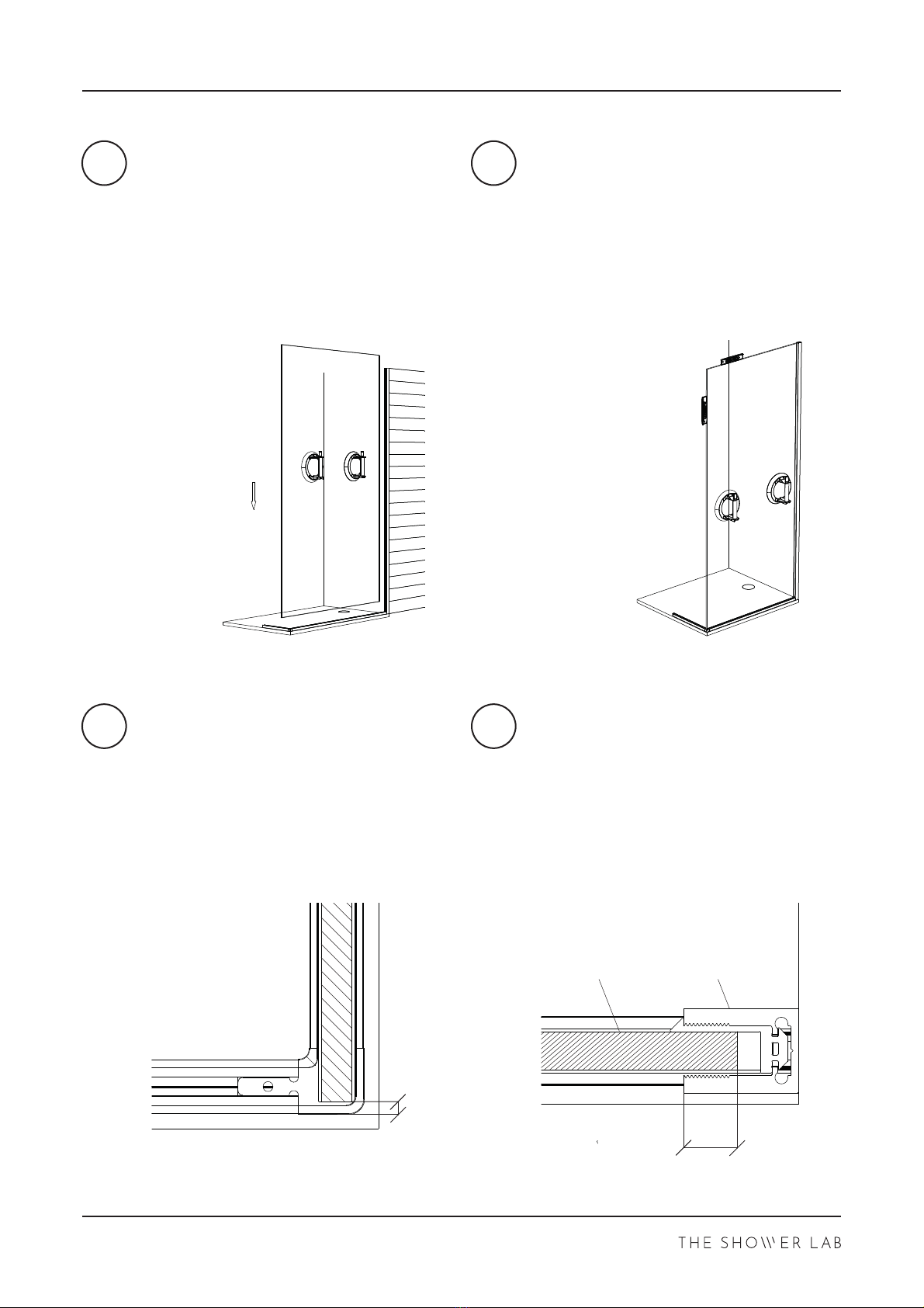
4mm
6mm min
Wall ProleGlass Panel
04/14
Using purpose built "Glass Liers",
posion and sit the Inline Glass Panel
on to the Underframe Gasket and push
against the Wall Profile.
Note the orientaon and posion of
the Panel, this can be determined by
any holes or aached labels.
Remove and replace the Panel adding
or subtracng spacers as necessary to
level the Panel (to a maximum height
of 5mm inside the Underframe).
Check the Panel is level using a Spirit
Level.
Align the Inline Panel so there is a 4mm
gap between the Panel and the front
face of the Return Underframe.
Ensure there is adequate glass in the
Wall Profile. (6mm is recommended)
13 14
15 16
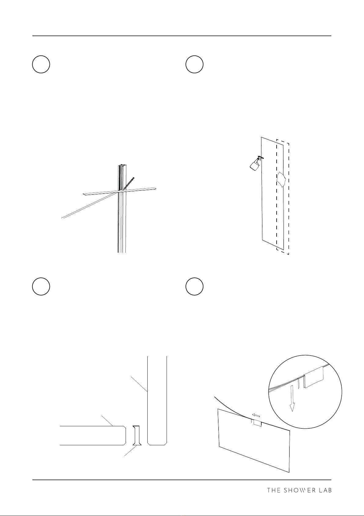
04/2021 V 1.0
VIEW 19F
Glass Return Panel
Glass Inline Panel
Glass to Glass Adhesive Tape
05/14
If the Wall Profile is flush with the Glass
Panel, move on to step 18.
If the Wall Profile is not flush with the
top of the Glass Panel, mark the Wall
Profile. Using a straight edge, mark
where the wall channel needs to be
trimmed.
To protect the channel finish, it is
recommended to mark on masking
tape.
Clean the edges of the Glass Inline
Panel and Return Panel where the
Glass to Glass Adhesive Tape will be
applied.
Before Installing the Glass to Glass
Adhesive Tape, ensure that the Tape is
orientated and posioned correctly on
the Glass Return Panel as shown below.
Posion the Glass to Glass Adhesive
tape on the correct edge of the Return
Panel. Using a cloth or towel, apply the
Tape to the Panel.
Peel back the protecve adhesive strip
while firmly applying the Tape.
Cut excess Tape using a blade.
17 18
19 20
Altri manuali per VIEW 19F
1
Indice
Altri manuali THE SHOWER LAB Cabina doccia

THE SHOWER LAB
THE SHOWER LAB VIEW 04 Manuale utente

THE SHOWER LAB
THE SHOWER LAB View 45 Manuale utente

THE SHOWER LAB
THE SHOWER LAB VIEW 07 Manuale utente

THE SHOWER LAB
THE SHOWER LAB VIEW 25 Manuale utente

THE SHOWER LAB
THE SHOWER LAB VIEW 25 Manuale utente

THE SHOWER LAB
THE SHOWER LAB VIEW 09 Manuale utente


