Thytronic SME70 Manuale utente
SME70, SME70-C, SME70-M - Installation Guide - 04-2020
SME70
SME70-C
SME70-M
DIRECTIONAL EARTH FAULT,
SHORT-CIRCUIT
AND VOLTAGE ELEMENTS
INSTALLATION
GUIDE
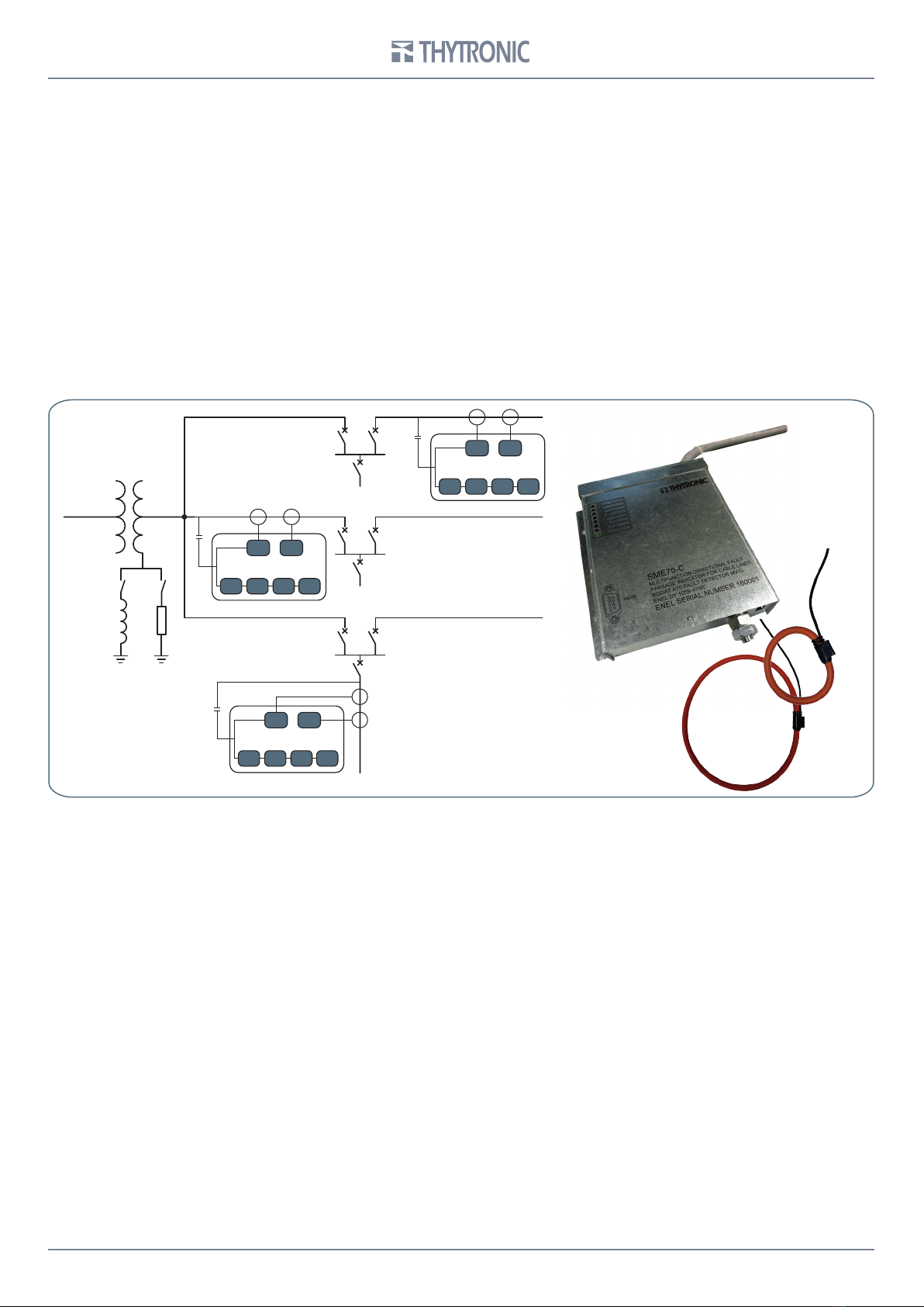
SME70
27V1 59 59V2 59N
51
67N
SME70
27V1 59 59V2 59N
51
67N
SME70
27V1 59 59V2 59N
51
67N
2SME70, SME70-C, SME70-M - Installation Guide - 04-2020
INTRODUCTION
—Scope and liability
The instructions for installation of SME70, SME70-C, SME70-M (SME70 INDOOR FAMILY) devices are
listed in this document.
This manual has been checked out, however, deviations from the description cannot be completely
ruled out, so that no liability in a legal sense for correctness and completeness of the information or
from any damage that might result from its use is formally disclaimed.
The information given in this document is reviewed regularly; any corrections and integration will be
included in subsequent editions that are identified by the date of revision.
We appreciate any suggestions for improvement.
We reserve the right to make technical improvements without notice.
—Technical support
Contact: THYTRONIC Technical Service www.thytronic.it
—Safety recommendations
The warming contained in this document are all-important for safety; special attention must be paid
to the following symbols:
Installation must be carried out by qualified person; Thytronic assumes no responsibility for damag-
es caused from improper use that does not comply all warning and caution in this manual.
In particular the following requirements must be met:
• Remove power before opening it.
• Verify the voltage absence by means suitable instrumentation on relay connections; attention must
be paid to all circuits supplied by external sources (binary input, analog inputs, etc...)
• Care must be taken when handling metal parts (front panel, connectors).
WARNING Death, severe personal injury or substantial property damage can result if proper precautions
are not taken.
CAUTION Minor personal injury or property damage can result if proper precautions are not taken.
3
SME70, SME70-C, SME70-M - Installation Guide - 04-2020
INSTALLATION
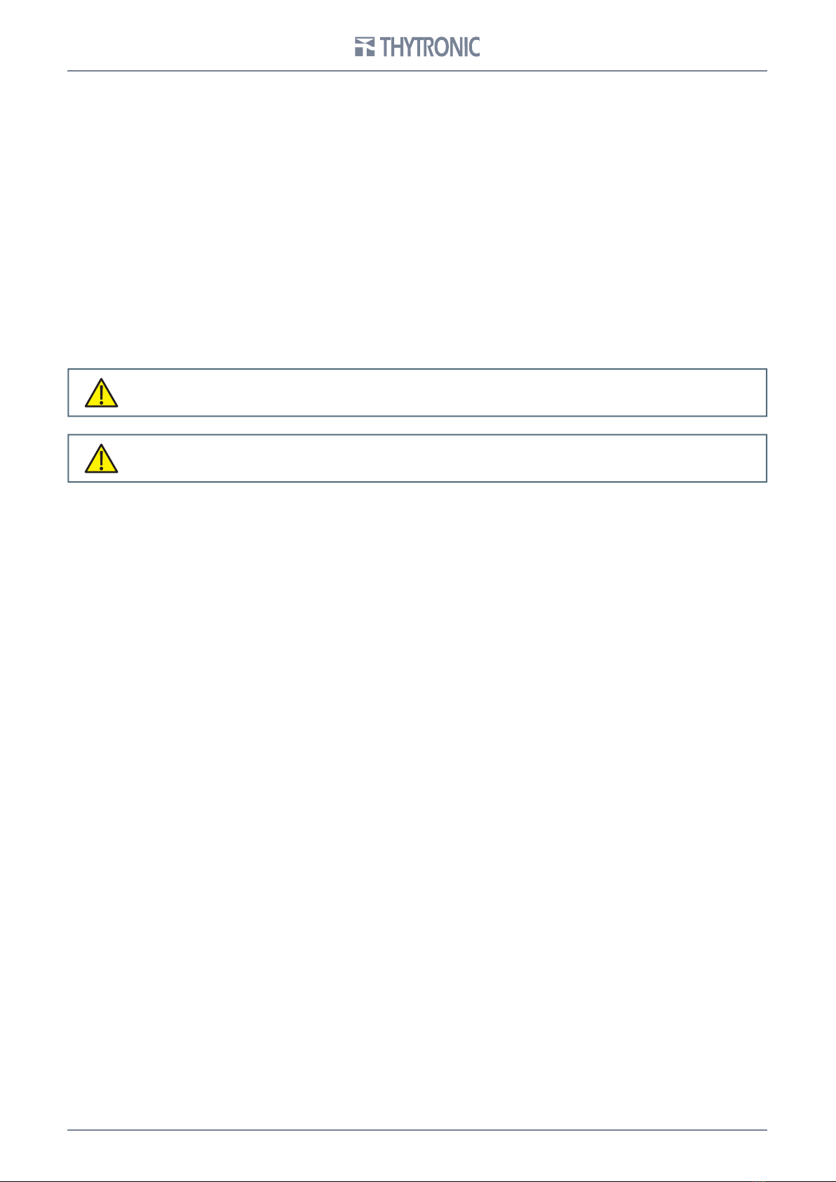
RESIDUAL CURRENT SENSOR
The residual current sensor must be crossed in the same direction by all active conductors and
hence, also by the neutral conductor if distributed, with the exception of the ground connection
protective conductor. The drawing below shows cases of assembly of the residual current sensor
on unscreened and screened cables; prior to proceeding with assembly, it is necessary to check
that there are no screen-to-ground connections upstream of the sensor.
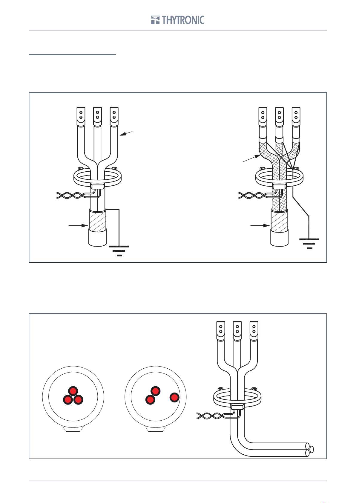
In order to ensure a linear response from the sensor, the cables must be positioned in the centre of
it so that the magnetic effect of the three cables is perfectly compensated in the absence of residual
current (Fig.2a).
Hence, the assembly indicated in the following drowing, in which phase L3 causes local magnetic
saturation whereby the vectorial sum of the three currents would be non-null, should be avoided.
The same considerations also apply when the sensor is positioned near bends in the cabling.
It is recommended that the transformer be placed away from bends in the conductors).
Armoring
Load Load
Source Source
Insulated cables
Shielded cables
Armoring
L1
L3L2
L1
L3
L2
4SME70, SME70-C, SME70-M - Installation Guide - 04-2020
SME70 equipment composition:
- n.1 SME70
- n.1 UP connection cable
- n.1 Capacitive divider connection cable
- n.1 Voltmetric socket
- n.4 Screws
SME70-C equipment composition:
- n.1 SME70
- n.1 UP connection cable
- n.2 Phase currenr sensors
- n.1 Residual current sensor
- n.1 3m rilsan sheath
- n.1 Capacitive divider connection cable
- n.1 Voltmetric socket
- n.4 Screws
SME70-M equipment composition:
- n.1 SME70
- n.1 UP connection cable
- n.1 Capacitive divider connection cable
- n.2 Phase currenr sensors
- n.1 Residual current sensor
- n.1 Crossbar for capacitive insulators
- n.3 Copper braids 50mm2
- n.3 Shielded interconnecting cables (capacitive insulators voltmetric socket)
- n.1 Voltmetric socket
- n.3 10pF capacitive voltage dividers
- n.1 Mechanical support for RGDAT and voltmetric socket
- n.4 Plastic straps
- n.1 3m rilsan sheath
- n.4 Screws
- n.4 Shakery washers
- n.4 Assembly nuts
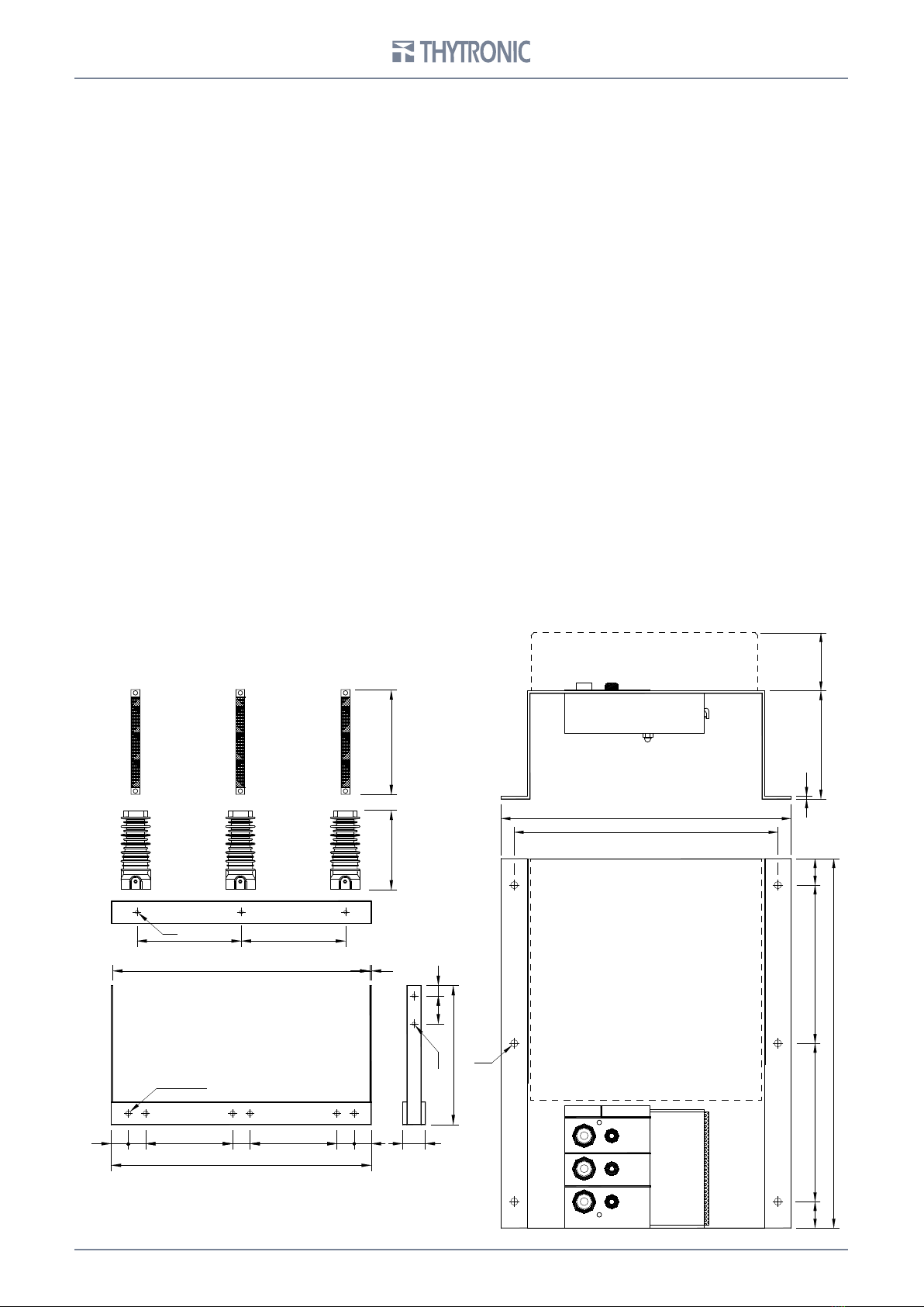
EARTH PHASE
4
8
12
82
Ø5.5
2
220
200
20 120 120 20
280
max 45
SME70-M
SME70-M
300 300
49 50 250 50 250 50 49
740 4
65
3080
400
225 300
748
Ø10
Ø10
N.6 HOLES Ø15
Copper braids Copper braids
Copper braids
Capacitive
insulator
Capacitive
insulator
Capacitive
insulator
5
SME70, SME70-C, SME70-M - Installation Guide - 04-2020
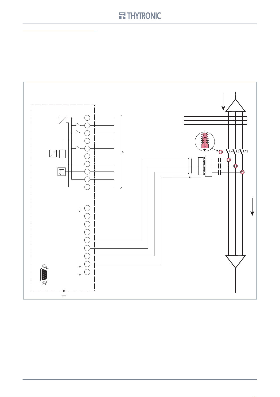
CONNECTION DIAGRAM SME-70
MB terminal block
TRIP
capacitive
divider
normal direction
of power
MA terminal block
SME70
0
8
7
1
2
3
4
6
5
Link to
remote control
unit [UP]
+
COMTS (+24 V)
TS 51A
TS PRES V
M1
TS 67AV
M2
UD
K1
K2
K3
D/A
COM UD
-24 V
1
2
3
4
5
6
7
8
9
10
RS232
Ground Spacer
6SME70, SME70-C, SME70-M - Installation Guide - 04-2020
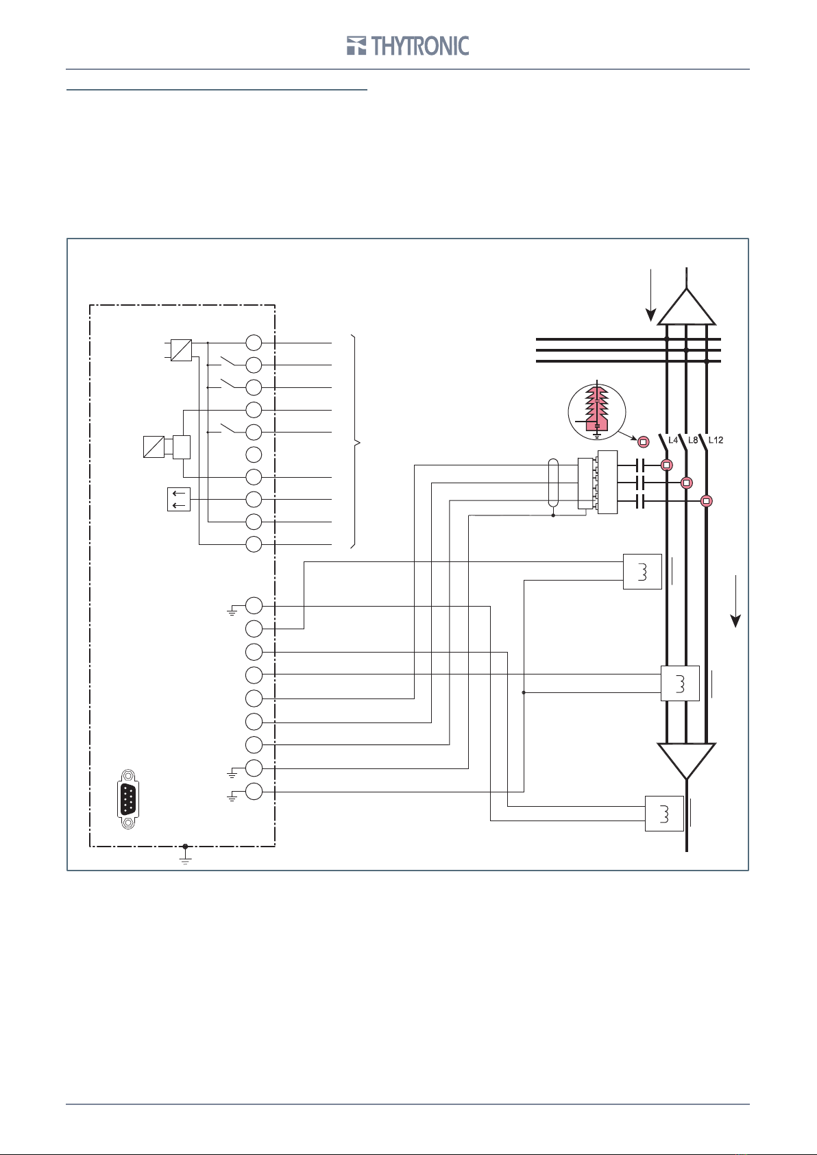
MB terminal block
I> current sensor
I> current sensor
IE> current sensor
TRIP
capacitive
divider
normal direction
of power
MA terminal block
SME70-C SME70-M
0
8
7
1
2
3
S1 P1
4
6
5
Link to
remote control
unit [UP]
+
COMTS (+24 V)
TS 51A
TS PRES V
M1
TS 67AV
M2
UD
K1
K2
K3
D/A
COM UD
-24 V
1
2
3
4
5
6
7
8
9
10
RS232
Ground Spacer
CONNECTION DIAGRAM SME70-C, SME70-M
7
SME70, SME70-C, SME70-M - Installation Guide - 04-2020
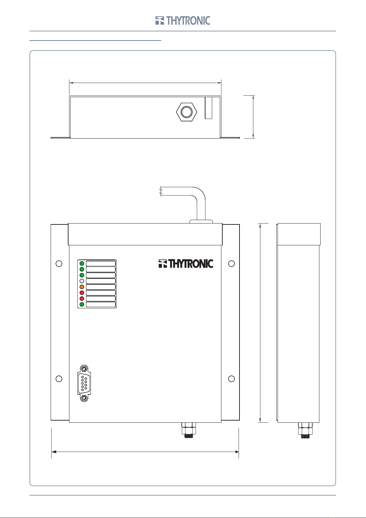
EXTERNAL VIEWS - SME70 INDOOR FAMILY
135
175
max40
R S 23 2
O N
F A IL
67A V
51A
IN V . 67
V 1 2
V 8
V 4
To Remote control unit [UP]
165
8SME70, SME70-C, SME70-M - Installation Guide - 04-2020
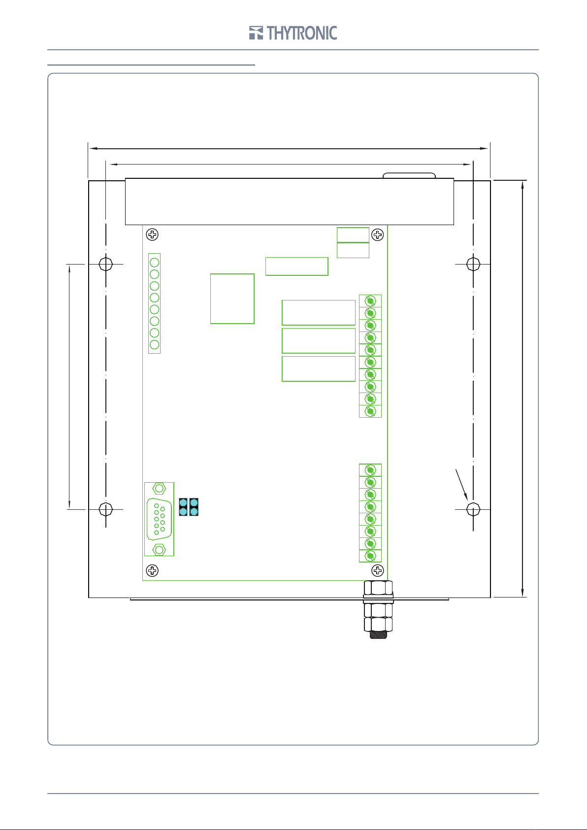
INTERNAL VIEWS - SME70 INDOOR FAMILY
165
173
100
Ø5.5
150
POWER SUPPLY
MA
TERMINAL BOARD
(SENSORS)
MB
TERMINAL BOARD
(REMOTE CONTROL UNIT)
RELAY
RELAY
RELAY
RS232
PE
X22
X21
CYBER
SECURITY
PRESET
9
SME70, SME70-C, SME70-M - Installation Guide - 04-2020
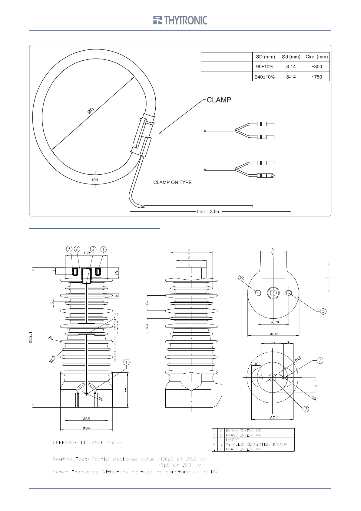
CURRENT SENSORS (SME70-C, SME70-M ONLY)
Phase Current
Residual Current
Residual sensor
0
Connect to MA according
to the terminal tag
Phase sensors
Connect to MA according
to the terminal tag
Connect to the ground
spacer
CAPACITIVE INSULATORS (SME70-M ONLY)

10 SME70, SME70-C, SME70-M - Installation Guide - 04-2020
VOLMETRIC SOCKET (SME70-M ONLY)
CROSSBAR FOR CAPACITIVE INSULATORS (SME70-M ONLY)
Questo manuale è adatto per i seguenti modelli
2


