Tidel TACC-IIa Manuale utente

TACC-IIa
Operator’s Manual
450-0299-001 REV. C

Copyright © 2004 by TIDEL ENGINEERING, L.P.
All rights reserved. No part of this manual may be reproduced, stored in a retrieval
system, or transmitted in any form or by any means, electronic, mechanical, photocopy-
ing, recording, or otherwise, except as may be expressly permitted by the applicable
copyright statutes or in writing by Tidel Engineering, L.P.
For information, write:
Tidel Engineering, 2025 W. Belt Line Rd, #114, Carrollton, TX 75006, (972) 484-3358

Table Of Contents
Component Location .................................................2
Loading the Operating Cash:......................................3
Checking the number of tubes ...................................4
Making Drops ............................................................4
Vending Operations: ..................................................5
Activate the Alternate Vend Delay Timer ...................6
Door Opening Procedures...........................................7
Notes on Door Opening ..............................................8
To Open the Door (Instant Access): ............................9
To Open the Door (Dual Function):.............................9
Closing the Door:.......................................................9
Dumping Tubes From the Magazine .........................10
Troubleshooting ......................................................11
1
4
3
2
1
4
6
7
89
5
10
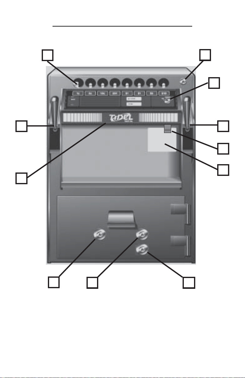
1) Tube Loading Gate
2) Tube Loading Gate Lock
3) Vending Keyswitch
4) Drop Chutes (2)
5) Control Panel
6) 1 AMP, Slow Blow Fuse
7) Serial Number Sticker
8) Door Bolt Lock
9) Manager Keyswitch
10) Courier Keyswitch
COMPONENT LOCATION
2

LOADING THE OPERATING CASH
Each one of the 8 columns will hold:
12 tubes – Serial numbers beginning with A91, A92 or A93.
11 tubes – Serial numbers beginning with IA.
Step 1: All coins should be wrapped. Do not place tape over the end
of the tube. Glue from the tape will eventually cause jams in
the magazine.
Note: If loose coins are to be loaded into the tubes, end caps
for the tubes can be purchased.
Step 2: Bills loaded into the tubes should be folded lengthwise and
inserted into the tubes.
Note: Approximately 30 bills can be placed in a tube, however,
bills that are “packed” into a tube will be difficult to remove
and will not lay flat in the cash register.
Step 3: Load tubes, closed end 1st, to prevent coins from falling out
of the tube and into the magazine, causing jams.
The key in the top right corner of the unit operates a “vend
tube lock bar”. This prevents unauthorized loading, (empty
tubes or the wrong denomination in the wrong column).
3

CHECKING THE NUMBER OF TUBES
IN THE TACC-IIa
Step 1: Insert the dipstick into the tube loading hole with the
highest number first.
Step 2: The number at bottom of tube loading hole is the number of
tubes in the magazine.
Note: Leaving the dipstick in the magazine may result in a
jammed vend mechanism.
Making Drops
Step 1: Pull the handle of the drop chute down.
Step 2: Insert the the drop FULLY into the drop chute and close the
drop chute
4

VENDING OPERATIONS
The Vending Key is located on the Control Panel.
When the Vending Key is OFF:
The wait light will remain on.
No tube can be vended.
The time delay continues to advance. If the key
is turned back to the ON position and the time
delay was achieved while the key was OFF, the
READY light will illuminate and a vend is
possible.
The Vending Key should be turned OFF when leaving the area of the
unit (to stock shelves or coolers, etc…). This prevents
unauthorized vending.
Step 1: The Vending Key must be in the ON position and the vend
delay time must be achieved before the READY light will
illuminate and a tube can be vended.
Step 2: To vend a tube, press the button which corresponds to the
column you wish to vend from.
Step 3: After a tube is vended, the vending time delay starts over,
and the operator must wait another 2 minutes before an-
other vend is possible.
5

TO ACTIVATE THE 30 SECOND
ALTERNATE VEND DELAY TIMER
The “Alternate Vend” feature allows the operator to change the vend
delay time from 2 minutes to 30 seconds (for peak activity periods).
To activate the 30 second Alternate Vend feature:
Step 1: Turn the Manager Key ON and release it. (the Manager Key
is spring loaded and should return to the off position).
Step 2: Press the “ALT VEND” button on the Control Panel.
Step 3: The ALT VEND light will illuminate momentarily.
Step 4: After a 10 minute time delay, the ALT VEND light will
illuminate.
The delay time between vends will be 30 seconds as long as
the ALT VEND light remains lit.
To return the unit to the standard 2 minute timer:
Step 1: Turn the Manager Key ON and release it. Then press the
“ALT VEND” button on the Control Panel.
Step 2: The ALT VEND light will go out and the unit will instantly
return to the standard 2 minute time delay.
Note: The Alternate vend timer cannot be activated while the
door is in an unlocked position.
6

DOOR OPENING PROCEDURES
Overflow from the cash register is deposited in the drop chutes on left
and right sides of the unit.
A divider is placed in the bottom of the unit to separate the 2 sides.
To retrieve items deposited into the drop chutes, the door must be
opened.
To open the door (Time Delay):
Step 1: Turn the Manager Key ON and release it, (the Manager Key
is spring loaded and should return to the off position).
Step 2: Within 30 seconds of turning the Manager Key, press the
“DOOR” button on the Control Panel.
Step 3: The DOOR light will illuminate momentarily.
Note: Early A91 series units did not require pressing the door
button after turning the Manager Key to start the door timer.
Step 4: A time delay of 10 minutes (units may be set for 3, 10 or 30
minute delay times), must be achieved before the door can
be opened.
Step 5: When the door delay time has been achieved, the DOOR
light will illuminate.
Door opening will be accessible for an additional 10-minute
window. During this 10-minute window, the door light will
remain lit.
Step 6: Turn the Door Bolt Key and open the door.
Note: units can be equipped with 3 or 30-minute door open-
ing delay timers.
7

NOTES ON DOOR OPENING
If the door is opened without waiting the door opening delay
time or if power is disconnected from the unit while the door is
open, the WAIT light will illuminate and no vends will be
possible.
To activate the vending functions again, turn the
Manager Key and release it.
If the Manager Key is held in the ON position for more than 30
seconds, all the lights on the Control Panel will begin flashing.
Operations cannot be performed while the unit is in this
lockout feature.
To return to normal operations, perform a power reset.
During the door opening delay time:
Tubes may be vended if the Vending Key is ON and the READY
light is illuminated.
The door opening procedure can be cancelled by pressing the
“DOOR” button on the Control Panel 3 times.
After the door is opened:
The DOOR light will remain on as long as the door is open.
There is no time limit on how long the door can stay open.
The Vending Key must be ON to vend tubes while the door is
open.
If the door bolt is extended while the door is open:
Turn the Manager Key and release it, then turn the door bolt
key to retract the door bolt.
Note: To activate the door locking bar solenoid on an early
A91 series unit, you must press the “DOOR” button on the
Control Panel.
8
Altri manuali per TACC-IIa
2
Indice
Altri manuali Tidel Sicuro


Manuali Sicuro popolari di altre marche


Honeywell
Honeywell 2077D - 1.21 Cubic Foot Anti-Theft Safe Manuale utente

Hornady
Hornady SnapSafe Trunk Safe II Manuale utente

SPORTS AFIELD
SPORTS AFIELD SA-HD5-BIO Manuale utente

Honeywell
Honeywell 5912 Manuale utente

Phoenix
Phoenix FS1280F Manuale utente

Phoenix
Phoenix SS0992K Scheda informativa del prodotto


