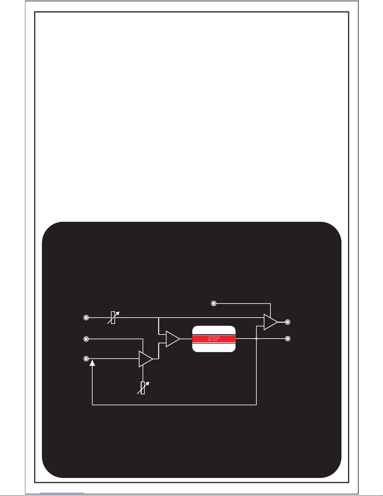
Tiptop Audio Z-DSP Manuale utente

+
+
+
+
Tipt p
A u d i o
FEEDBACK 1
SEQUENTIAL PROGRAM CONTROL
DSP
2
1
∑
FEEDBACK 2
IN 2IN 1
Tiptop Audio
VC-DSP2 VC-DSP3VC-DSP1
VC-P1 VC-P2 CLOCK
VC-P3
FEDBK1 FEDBK2
OUT2OUT1
TRIGGER FWD/REV VC-PRG
AUDIO IN AUDIO IN
1
FEDBK IN
2
FEDBK IN
VC VC
VC
2 4 B i t / Variable
Clock
MIN MAXMIN MAXMIN MAX MIN MAX
MIN MAX
MIX
DRY WET
MIN MAX
MIN MAX
R
1 2
L
Z-DSP VC-DIGITAL SIGNAL PROCESSOR
Z-DSP
Z-DSP
+
+
+
+
Tipt p
A u d i o
FEEDBACK 1
SEQUENTIAL PROGRAM CONTROL
DSP
2
1
∑
FEEDBACK 2
IN 2IN 1 VC-DSP2 VC-DSP3VC-DSP1
VC-P1 VC-P2 CLOCK
VC-P3
FEDBK1 FEDBK2
OUT2OUT1
TRIGGER FWD/REV VC-PRG
AUDIO IN AUDIO IN
1
FEDBK IN
2
FEDBK IN
VC VC
VC
2 4 B i t / Variable
Clock
MIN MAXMIN MAXMIN MAX MIN MAX
MIN MAX
MIX
DRY WET
MIN MAX
MIN MAX
R
1 2
L
Z-DSP VC-DIGITAL SIGNAL PROCESSOR
Mark Pulver
Gur Milstein
Written By
User Manual

Z-DSP VC-Digital Signal Processor
Design - Gur Milstein
Tiptop Audio 2009 All Rights Reserved
MADE IN THE USA
Special Thanks
Shawn Cleary
Matthew Davidson
Andreas Schneider
Bobby Voso
James Cigler
Alessandro Cortini
Richard Devine
Surachai Sutthisasanakul
Matrix
Special thanks to Mark Pulver
for all the help and support in
making this project a reality.

Contents.
Introduction
Getting Started
Signal Flow
Analog Feedback
Digital Feedback
Reading the Panel
A built-in Guitar Preamp
Looking into Voltage Control
Understanding Clocking
Program Switching

Introduction.
Welcome to the world of digital signal processing!
The Z-DSP is a modular synthesizer component that
can process and generate audio using a dedicated
micro-computer, a digital signal processing processor –
a DSP!
Like the processor in your desktop computer, the
Z-DSP runs programs in memory. It’s these programs
that create the delays, filters, oscillators and more that
the Z-DSP can produce. The possibilities are virtually
endless, limited only by the imagination of those who
write the applications for it. Tiptop Audio, together with
some of the best known programmers in the music
industry, are working to bring programs to the Z-DSP
platform.
The Z-DSP uses an open-source coding environment,
and using a programmer (available from Tiptop/Spin
Semiconductor) anyone can create, share or sell their
own applications for the Z-DSP. We hope that this
unique feature will motivate more designers and users
to dive in to the amazing world of digital signal
processing and enrich the available library of
applications for the Z-DSP platform. Please contact us
for more information regarding obtaining a programmer.
TM
Z-DSP

Getting Started.
The Z-DSP itself contains no programs, it loads
programs from a cartridge. If the module is powered
up without a cartridge inserted it will show
“insert cartridge” on the display
The module is sold with the Dragonfly Delay cartridge,
which contains 8 delay programs. Pull it out of the
bag now and insert it slowly to the card slot on the
front of the Z-DSP, making sure that the Dragonfly
print is facing upward. Note: Inserting the card upside
down will not cause any damage, but the card will not
work.
After a moment, the Z-DSP will load the program found
in memory slot 1 on the cartridge. Some cartridges will
display a message when first inserted. For example, the
Dragonfly Delay will first show the name and author of
the algorithms, then show a reminder that audio needs
to be connected to both inputs to achieve a stereo
effect. Note: A Tiptop Stack Cable is ideal for bridging
inputs!
The cards can be inserted and removed at any time,
even during audio processing. Pulling the card out at
this point will keep the current program loaded and the
display will again show "insert cartridge". Now that we
have a program loaded into the processor, let’s have a
look at the Z-DSP signal flow.

Signal Flow.
INSERT CARTRIDGE
The Z-DSP contains two distinct audio channels,
labeled Left (also “1”) and Right (also “2”). The
terminology of “Left” and “Right” is most commonly
used for stereo effects like Delay and Reverb, while
“Channel 1” and “Channel 2” would be used in
applications that deal with more diverse names such
as Carrier and Signal in a ring modulator.
The Z-DSP is truly stereo, no summers allowed! Each
channel is built from a distinct audio input , feedback
input, processing block, audio output and feedback
output.
FEDBK OUT
OUT
VCA
MIX
FEDBK IN
AUDIO IN
VC
VC MIX
FEEDBACK
GAIN
DSP
MIX
SINGLE CHANNEL IS SHOWN

Analog Feedback.
INSERT CARTRIDGE
Feedback is the process of taking an output and
applying it (“feeding” it) back into an input. This
technique is widely used in audio for a variety of
applications and is an especially strong tool in DSP
allowing samples to be re-processed.
The Z-DSP offers an open-loop-feedback architecture
which means that the user has the freedom to insert
other processing devices in the feedback loop.
For example, analog filters, frequency shifters, other
DSP processors, etc.
The Feedback Input contains a VCA that allows control
of the gain of the feedback loop. Given that this is a
VCA, you can control the gain from any voltage
source. The VCA is very responsive to control input
and can be swept up into the audio range for even
more wild feedback effects.
The feedback loop on the Z-DSP is hardwired internally
so with nothing plugged into the Feedback Input jack,
it is fed from the 100% wet Feedback Output. Turning
the Feedback Input knob clockwise will introduce more
signal back into the input of the channel. Inserting a
plug into the Feedback Input jack will break the loop.
The feedback section has a good amount of gain in it,
and will easily cause the module to self-oscillate. This
can result in some high frequency 'screeching' which
can harm your monitors. So take it easy on that gain
knob if you’re looking for smoother sounds.

Digital Feedback.
INSERT CARTRIDGE
Some algorithms process feedback internally, in the
digital domain. The texture of digital feedback is much
different and brings a very different flavor than analog
feedback. Combining analog and digital feedback will
bring even more depth to a sound.
You’ll know that a program is using digital feedback
from FDBK showing on the display as a parameter.

Reading the Panel.
INSERT CARTRIDGE
The Z-DSP front panel contains graphics and
typography to help you understand the signal flow and
to indicate the functions of the knobs and jacks.
Some shortcuts used are:
FEDBK or FDBK Feedback
VCP1 Voltage control digital Parameter 1
VC-PRG Voltage Controlled Program
FWD/REV Forward/ Reverse
I/O In / Out
From top-to-bottom/left-to-right the panel contains:
•LCD display
•Audio inputs jacks and knobs
•DSP parameter control knobs
•Feedback input jacks and knobs
•DSP parameter control CV inputs
•Clock/Sample rate jack
•An audio clipping led indicator
•Audio and Feedback Output jacks
•DSP cartridge socket
•A Wet/Dry knob and CV jack
•A program select switch along with 3
jacks for sequential program switching
using either VC or trigger/gate signals
In total there are 8 pots and 18 jacks.

A built-in Guitar Preamp.
INSERT CARTRIDGE
The Z-DSP contains a simple monophonic Guitar
preamp that can be enabled by 2 jumpers at the back
of the unit.
The first jumper allows a choice between synth (line)
level and guitar level.
The second jumper enables the preamp for both
inputs, or just the Left input.
In any case, a guitar should be connected to the Left
channel input only and let the second jumper control
the routing to the Right input.
HD6
enable preamp for both inputs
1
2
3
2
1
HD5
2&3 = synth level 1&2 = guitar level
1
2
3
HD5
Altri manuali per Z-DSP
1
Indice
Altri manuali Tiptop Audio Hardware per computer
Manuali Hardware per computer popolari di altre marche

EMC2
EMC2 VNX Series Manuale del proprietario

Panasonic
Panasonic DV0PM20105 Manuale utente

Mitsubishi Electric
Mitsubishi Electric Q81BD-J61BT11 Manuale utente

Gigabyte
Gigabyte B660M DS3H AX DDR4 Manuale utente

Raidon
Raidon iT2300 Manuale utente

National Instruments
National Instruments PXI-8186 Manuale utente


