Titanium MIG 170 Manuale utente

!"#$%&'()*+,
-.'./&)01&*23'./2&4/5&(//6577***,(413)1812.9(/,:);
<;4.=&)01&/2:(+.:4=&'066)1/&4/5&61)>0:/'066)1/?(413)1812.9(/,:);
MIG140
MIG170
57863 57864
Owner’s Manual & Safety Instructions
Save This Manual Keep this manual for the safety warnings and precautions, assembly,
operating, inspection, maintenance and cleaning procedures. Write the product’s serial number in the
back of the manual near the assembly diagram (or month and year of purchase if product has no number).
Keep this manual and the receipt in a safe and dry place for future reference. 20g
When unpacking, make sure that the product is intact
and undamaged. If any parts are missing or broken,
please call 1-888-380-0318 as soon as possible.
Copyright© 2020 by Harbor Freight Tools®. All rights reserved.
No portion of this manual or any artwork contained herein may be reproduced in
any shape or form without the express written consent of Harbor Freight Tools.
Diagrams within this manual may not be drawn proportionally. Due to continuing
improvements, actual product may differ slightly from the product described herein.
Too ls r eq ui red fo r as se mbly a nd s er vice m ay n ot be in cl ud ed .
Read this material before using this product.
Failure to do so can result in serious injury.
SAVE THIS MANUAL.
Page 7@)1&/2:(+.:4=&A02'/.)+'B&6=24'2&:4==&CD###DE#FDFEC#,Item 57863 57864
GH@<IJKHLMI<MHMN< OHGLN&P<QRLMSP<QRLMS&ILTG G<IUT
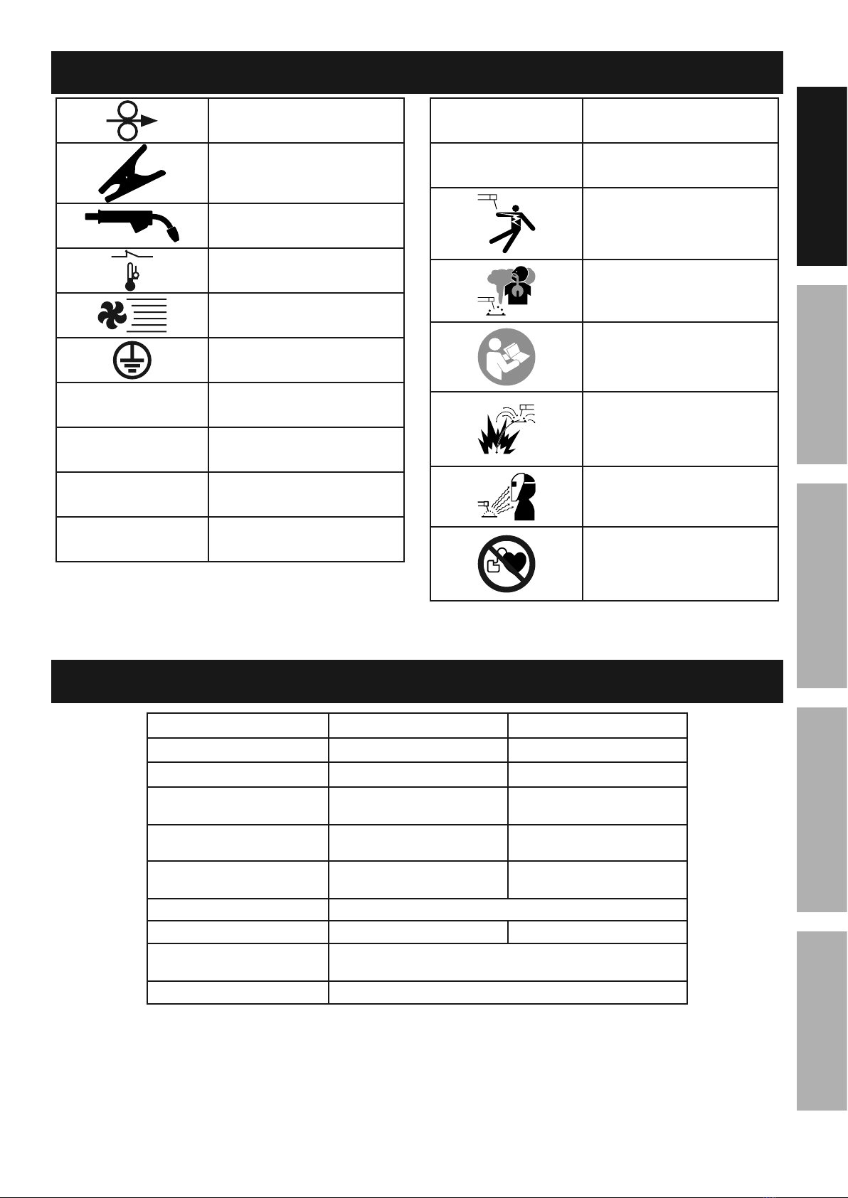
GX;3)=)9X
Wire Feed (Speed)
Workpiece Ground Cable
Torch Cable
Overheat Shutdown Indicator
Cooling Fan
Housing Ground Point
-HN Volts Alternating Current
HAmperes
WN- Open Circuit Voltage
Z-HKilovolt Amperes
(Volts / 1000 * Amperes)
LTK Inches Per Minute
HPS American Wire Gauge
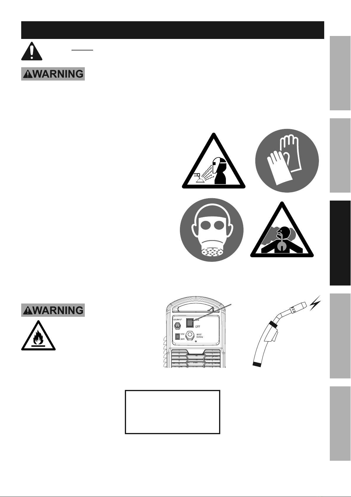
Electric Shock Hazard.
Do not touch energized parts.
Inhalation Hazard.
Keep head out of fumes
and use proper ventilation.
Read manual before
setup and/or use.
Fire Hazard.
Keep flammable materials
away during welding. Spatter
can cause accidental fires.
Arc Ray Hazard.
Wear welding helmet with
properly rated filter lens.
Pacemaker Hazard.
Welding processes may
interfere with pacemakers.
Consult doctor before use.
G62:.8.:4/.)+'
K)>2= KLS&C%F KLS&C"F
L/2; 57863 57864
T)*21&L+60/ 120 VAC / 60 Hz 120/240 VAC / 60 Hz
N0112+/&L+60/ 23 A 24 A @ 120V
26.8 A @ 240V
P2=>.+9&N0112+/&V4+92 30 –140 A 120V: 30-140A
240V: 30-170A
V4/2>&R0/X&NX:=2 30% @ 90 A 40% @ 90 A, 120V input
25% @ 160A, 240V input
W62+&N.1:0./&-)=/492 69 VDC
P.12&G622> 80 – 275 IPM 80 – 400 IPM
P2=>.+9&P.12&N464:./X Solid Core: 0.025" / 0.030" / 0.035"
Flux Cored: 0.030" / 0.035"
P.12&G6))=&N464:./X Up to 12 lb spool
Page 8 @)1&/2:(+.:4=&A02'/.)+'B&6=24'2&:4==&CD###DE#FDFEC#, Item 57863 57864
GH@<IJ KHLMI<MHMN<OHGLN&P<QRLMS P<QRLMS&ILTGG<IUT
M)/25 Wire Spool sold separately.
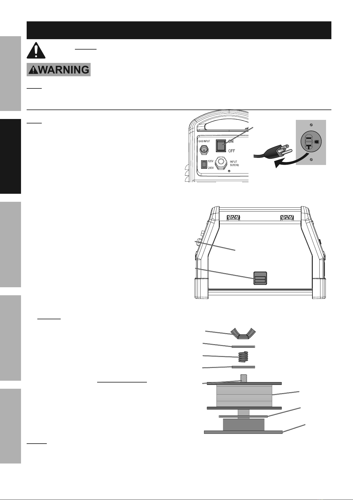
1. I01+&/(2&T)*21&G*./:(&W@@&4+>&0+6=09&
/(2&P2=>21&328)12&61):22>.+9,
2. Pull up on the Door Latch,
then open the Door.
3. b&T)0+>&P.12&G6))=&L+'/4==4/.)+5
Remove the Wingnut, Keyed Washers, and
Spring. If replacing a Spool, remove the old
Spool and all remaining wire from the liners.
4. Place the new Wire Spool over the Spool Spindle
and against the Spool Brake Pad as illustrated.
I)&612Y2+/&*.12&822>&61)3=2;'B&'2/&/(2&G6))=&
')&/(4/&./&*.==&0+*.+>&:)0+/21:=):]*.'2,
5. Line up the Keyed Washers with
the groove on the Spindle. Replace
the Keyed Washers and Spring
over the Spool Spindle and secure
Spool in place with the Wingnut.
M)/.:25 If Wire Spool can spin freely, Wingnut is too
loose. This will cause the welding wire to unravel and
unspool which can cause tangling and feeding problems.
T)*21&
G*./:(
R))1&
Q4/:(
R))1
P2=>21&
P4==
P.+9+0/
b&=3&&
P.12&G6))=
G6))=&
O14]2&T4>
Z2X2>&
P4'(21
Z2X2>&
P4'(21
G61.+9
G6))=&
G6.+>=2
b&=3&G6))=&Q)4>.+9
G2/06
V24>&/(2&<MILV<&LKTWVIHMI&GH@<IJ&LM@WVKHILWM&'2:/.)+&4/&/(2&329.++.+9&)8&/(.'&;4+04=&
.+:=0>.+9&4==&/2\/&0+>21&'03(24>.+9'&/(212.+&328)12&'2/&06&)1&0'2&)8&/(.'&61)>0:/,
IW&TV<-<MI&G<VLWUG&LMcUVJ&@VWK&HNNLR<MIHQ&WT<VHILWM5&
I01+&/(2&T)*21&G*./:(&)88&4+>&0+6=09&/(2&P2=>21&328)12&'2/06,
M)/25&Remove the protective foam and cardboard from the Welder before setup.
Wire Spool Installation / Wire Setup
Page 9@)1&/2:(+.:4=&A02'/.)+'B&6=24'2&:4==&CD###DE#FDFEC#,Item 57863 57864
GH@<IJKHLMI<MHMN< OHGLN&P<QRLMSP<QRLMS&ILTG G<IUT
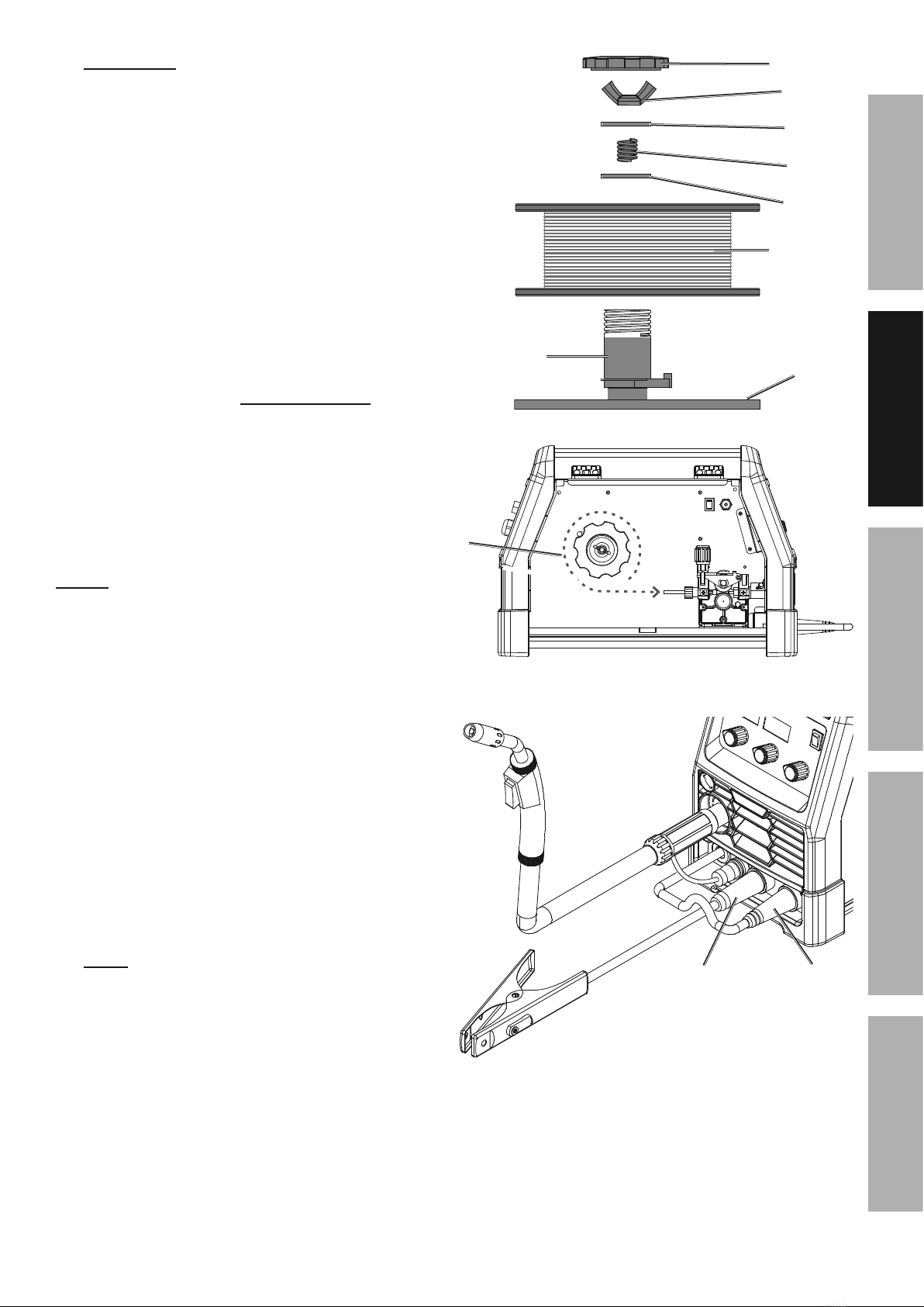
6. CFDCb&T)0+>&P.12&G6))=&L+'/4==4/.)+5&
Remove the Wingnut, Keyed Washers, and Spring.
If replacing a Spool, remove the old Spool
and all remaining wire from the liners.
7. Place the Spool Adapter over the Spool Spindle
and against the Spool Brake Pad as illustrated.
8. Place the new Wire Spool over the Adapter and
line up pin on Adapter with hole in Spool.
I)&612Y2+/&*.12&822>&61)3=2;'B&'2/&/(2&G6))=&
')&/(4/&./&*.==&0+*.+>&:)0+/21:=):]*.'2,
9. Line up the Keyed Washers with the groove
on the Spindle. Replace the Keyed Washers
and Spring over the Spool Spindle and
secure Spool in place with the Wingnut.
M)/.:25 If Wire Spool can spin freely, Wingnut
is too loose. This will cause the welding
wire to unravel and unspool which can
cause tangling and feeding problems.
10. Screw the Spool Knob into the Spool Adapter.
11. RN<M&R.12:/&N0112+/&<=2:/1)>2&M294/.Y2&&
Wire Setup for Flux-Cored (gasless) welding:
Connect the Wire Feed Connector to the
Negative Terminal on the front of the Welder.
Connect the Ground Cable to the
Positive Terminal on the front of the Welder.
CFDCb&=3&G6))=&Q)4>.+9
P2=>21&
P4==
CFDCb&=3&&
G6))=&
H>46/21
P.+9+0/
Z2X2>&
P4'(21
G61.+9
Z2X2>&
P4'(21
CFDCb&=3&&
P.12&G6))=
G6))=&Z+)3
P.12&
;0'/&
0+*.+>&
.+&/(.'&
>.12:/.)+
RN<M&&
Flux-Cored (Gasless) Polarity Setup
:)++2:/&
P.12&@22>&
/)&+294/.Y2
:)++2:/&
S1)0+>&/)&
6)'./.Y2
Page 10 @)1&/2:(+.:4=&A02'/.)+'B&6=24'2&:4==&CD###DE#FDFEC#, Item 57863 57864
GH@<IJ KHLMI<MHMN<OHGLN&P<QRLMS P<QRLMS&ILTGG<IUT
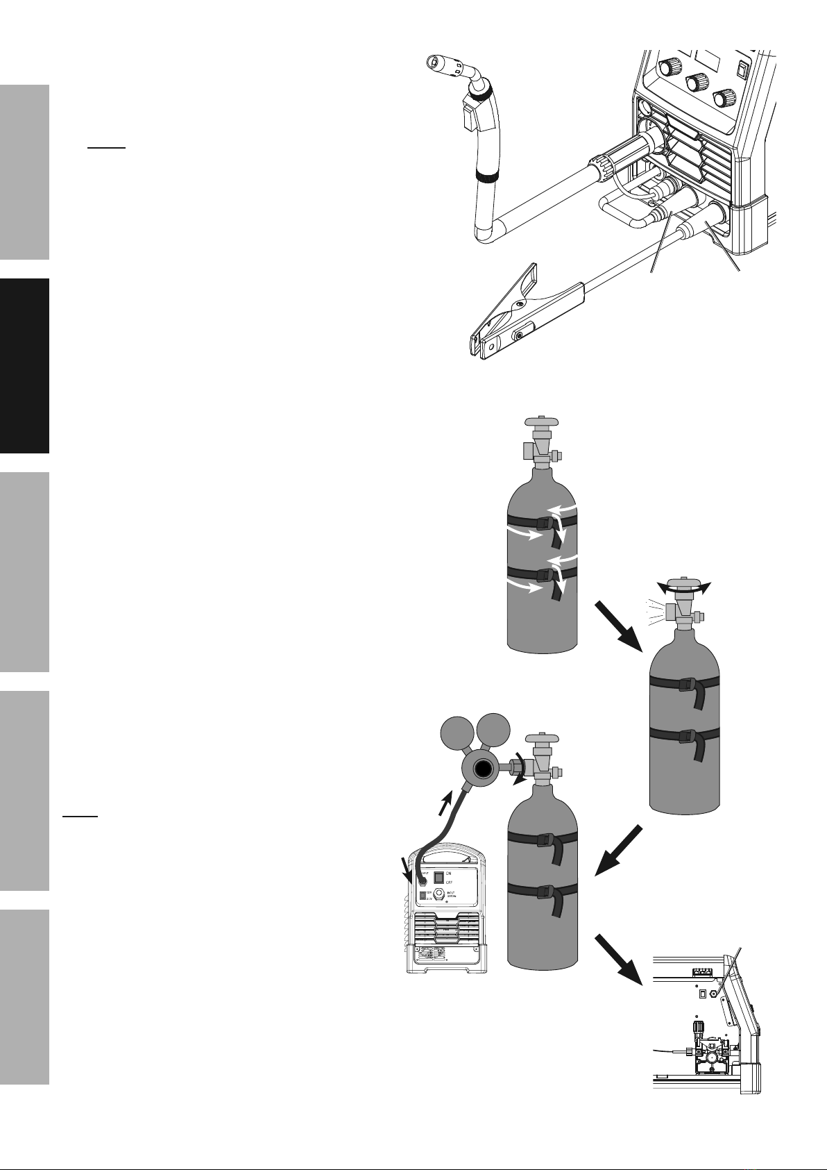
12. RN<T&R.12:/&N0112+/&<=2:/1)>2&T)'./.Y2&P.12&
Setup for Solid Core (gas shielded) welding:
a. Connect the Wire Feed Connector to the
Positive Terminal on the front of the Welder.
Connect the Ground Cable to the
Negative Terminal on the front of the Welder.
b. Determine which type of shielding gas
would be appropriate for the welding
you will do. Refer to the Settings Chart
on the inside of the Welder door.
c. With assistance, set the cylinder (not included)
onto a cabinet or cart near the Welder
and secure the cylinder in place with two
straps (not included) to prevent tipping.
d. Remove the cylinder’s cap. Stand to the
side of the valve opening, then open the
valve briefly to blow dust and dirt from the
valve opening. Close the cylinder valve.
e. Locate the Regulator (included) and close its
valve until it is loose, then thread Regulator
onto cylinder and wrench tighten connection.
M)/25 When using C100 shielding gas, connect a CGA
580/320 adapter (not included) to the inlet connection
of the Regulator and wrench tighten. Thread the
adapter onto the gas cylinder and wrench tighten.
f. Attach the Gas Hose (included) to the
Regulator’s outlet and the Welder’s gas inlet.
Wrench-tighten both connections.
g. Connect the Wire Feed Gas Hose within
the Welder to the Gas Quick Connector.
The collar on the Gas Quick Connector must
click into place after attaching any hose to it.
S4'&d0.:]&
N)++2:/)1
9
82
:
O1.28=X&)62+&Y4=Y2&
/)&:=24+B&&
/(2+&:=)'2&&
Y4=Y2,
>
RN<T&&
Solid Core (Gas Shielded) Polarity Setup
:)++2:/&
S1)0+>&/)&
+294/.Y2
:)++2:/&
P.12&@22>&
/)&6)'./.Y2
Page 11@)1&/2:(+.:4=&A02'/.)+'B&6=24'2&:4==&CD###DE#FDFEC#,Item 57863 57864
GH@<IJKHLMI<MHMN< OHGLN&P<QRLMSP<QRLMS&ILTG G<IUT
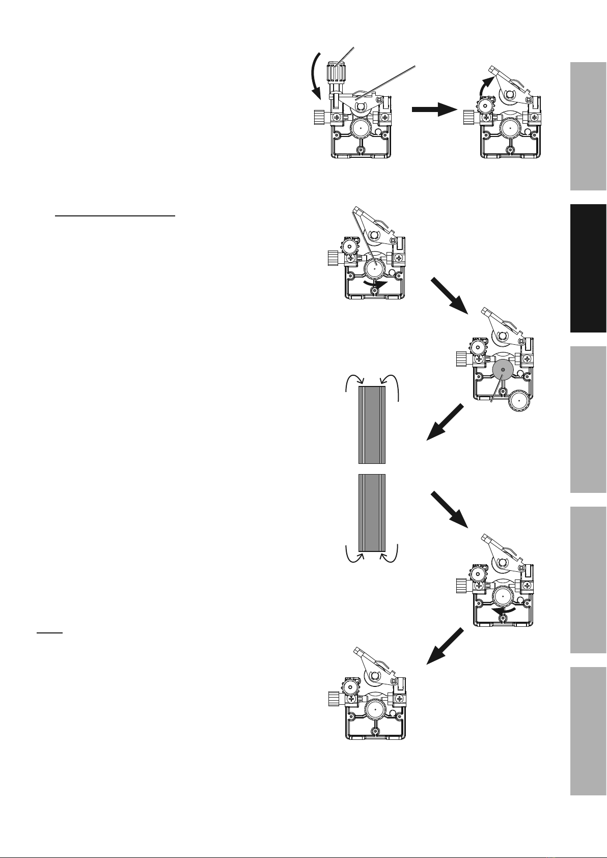
13. Turn the Feed Tensioner knob counterclockwise to
loosen it enough to pull it down to remove tension.
The spring-loaded Idler Arm will move up as shown.
14. @22>&V)==21&L+'/10:/.)+'5&
Check that the Feed Roller is correct for the
type of wire being used (solid core or flux-
cored) and that it is turned to properly match
the wire size marked on the Wire Spool:
a. Unscrew the Feed Roller Knob counterclockwise.
b. Remove the Feed Roller Knob to
expose the Feed Roller.
c. Flip or replace the Feed Roller as needed and
confirm that it is the correct Roller for the type of
wire being used and that /(2&+0;321&'()*.+9&
.'&/(2&'4;2&4'&/(2&*.12&>.4;2/21&)+&/(2&G6))=,
M)/25 The knurled groove is used for flux-cored wire.
The V-grooves are used for solid / MIG wire.
d. Screw the Feed Roller Knob back into
place to secure the Feed Roller.
L>=21&H1;
@22>&I2+'.)+21
@22>&V)==21&
Z+)3
@22>&
V)==21&
HH
OO
NN
RR
F,FEF&
-D91))Y2
F,Fb!&&
-D91))Y2&
G)=.>&N)12&
-DS1))Y2
F,FE!&
-D91))Y2
F,FEF&7&F,FE!&
]+01=2>&91))Y2
Page 12 @)1&/2:(+.:4=&A02'/.)+'B&6=24'2&:4==&CD###DE#FDFEC#, Item 57863 57864
GH@<IJ KHLMI<MHMN<OHGLN&P<QRLMS P<QRLMS&ILTGG<IUT
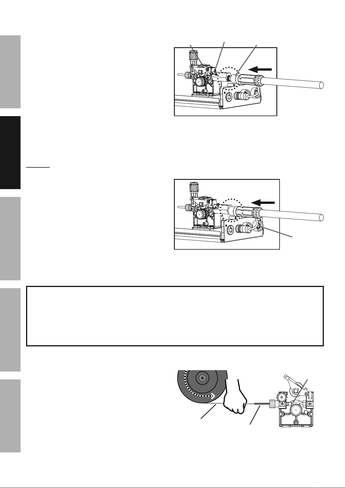
15. Loosen the Knob on the Wire Feed
mechanism, then insert the Gun Cable
Connector through the hole on the Welder
front and into the socket on the Wire Feed.
16. Ensure that the Gun Cable Connector is fully
inserted into the socket on the Wire Feed
mechanism as shown.
M)&WD1.+9&'()0=>&32&Y.'.3=2,
Tighten the Knob securely.
If Connector is not fully inserted, the gas
connection will leak, preventing shielding
gas from reaching the welding arc.
MWILN<5 To prevent damage,
do not overtighten the Knob.
17. Connect the Wire Feed Control Cable to the
Wire Feed Control Socket located on the front
of the machine. Press it in until the collar snaps
into place. Note that the plug on the Cable fits
into the Socket in one specific orientation only.
To disconnect it, pull the collar back first.
LKTWVIHMI
G2:012=X&()=>&)+/)&/(2&2+>&)8&/(2&*2=>.+9&*.12&4+>&]226&
/2+'.)+&)+&./&>01.+9&/(2&8)==)*.+9&'/26',
L8&/(.'&.'&+)/&>)+2B&/(2&*2=>.+9&*.12&*.==&0+14Y2=&4+>&0+'6))=&
*(.:(&:4+&:40'2&/4+9=.+9&4+>&822>.+9&61)3=2;',
18. Cut off all bent and crimped wire.
The cut end must have no burrs or
sharp edges; cut again if needed.
19. Keep tension on the wire and guide at
least 12 inches of wire into the Wire
Inlet Liner and Feed Guide.
Incorrect – Connector not fully insertedIncorrect – Connector not fully inserted
S0+&N43=2&
N)++2:/)1
P.12&@22>&
K2:(4+.'; Z+)3
Correct – Connector fully insertedCorrect – Connector fully inserted
P.12&
@22>&
N)+/1)=&
N43=2
P.12&P.12&
G6))=G6))=
P2=>.+9&
P.12
^WQR&PLV<&
G<NUV<QJ
@22>&
S0.>2
P.12&L+=2/&
Q.+21
Page 13@)1&/2:(+.:4=&A02'/.)+'B&6=24'2&:4==&CD###DE#FDFEC#,Item 57863 57864
GH@<IJKHLMI<MHMN< OHGLN&P<QRLMSP<QRLMS&ILTG G<IUT
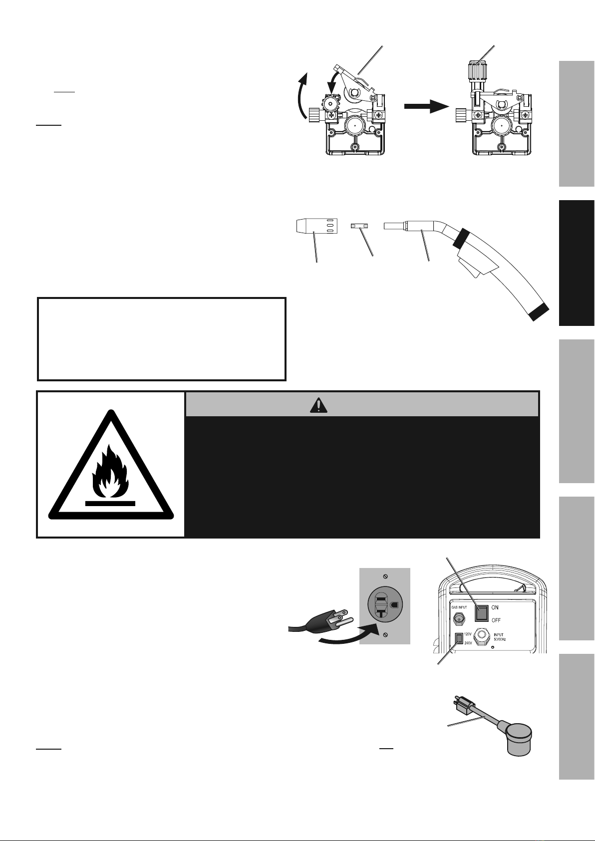
20. Make sure the welding wire is resting in the groove
of the Feed Roller, then push the wire Idler Arm
down, and swing the Feed Tensioner up to latch it
across the tip of the arm.
After the wire is held by the Tensioner,
you may release it.
M)/25 The tension should be 3 – 5 for solid wire and
2 – 3 for flux-cored wire. Too much force on flux-cored
wire will crush it and may cause feeding issues.
21. Pull and twist the Nozzle to remove it.
22. Unscrew the Contact Tip
counterclockwise and remove.
23. Lay the MIG Gun Cable out in a straight line so
that the welding wire moves through it easily.
Leave the cover open, so that the feed
mechanism can be observed.
LKTWVIHMI
G/4.+=2''&'/22=&*.12&.'&=2''&8=2\.3=2&/(4+&
)/(21&*2=>.+9&*.12,&&I(2128)12B&./&.'&;)12&
>.88.:0=/&/)&822>&/(1)09(&/(2&=.+21&4+>&90+,&&
L/&.'&2'62:.4==X&.;6)1/4+/&/)&]226&/(2&90+&:43=2&
'/14.9(/&*(.=2&822>.+9&'/4.+=2''&'/22=&*.12,
PHVMLMS
The following steps require applying power to the Welder
with the cover open.
I)&612Y2+/&'21.)0'&.+_01X&81);&8.12&)1&2=2:/1.:&'():]5
1. R)&+)/&/)0:(&4+X/(.+9B&2'62:.4==X&+)/&/(2&S1)0+>&N=4;6B&
*./(&/(2&S0+&)1&*2=>.+9&*.12&)1&4+&41:&*.==&32&.9+./2>,
2. R)&+)/&/)0:(&.+/21+4=&P2=>21&:);6)+2+/'&
*(.=2&./&.'&6=0992>&.+,
24. Turn the Power Switch off and do not touch the
Gun’s Trigger and before connecting Power Cord:
a. !"#$E&)+=X5 Plug the Power Cord into a
properly grounded, GFCI protected 120 VAC
(20 amp rated) receptacle that matches the
plug and turn the Power Switch ON.
b. !"#$%&)+=X5 LKTWVIHMI5&N(4+92&/(2&
-)=/492&G*./:(&)+&/(2&34:]&)8&/(2&P2=>21&
/)&/(2&Y)=/492&)8&/(2&)0/=2/&X)0&*.==&0'2,
If using 120VAC, connect the included
adapter to the end of the Power Cord. If using
240VAC, do not use the adapter. Plug the
Power Cord into a properly grounded and rated
receptacle that matches the plug and selected
voltage and turn the Power Switch ON.
M)/25 The circuit must be equipped with delayed
action-type circuit breaker or fuses.
L>=21&H1; @22>&I2+'.)+21
T)*21&
G*./:(
-)=/492&
G*./:(&
(57864 only)
b%F-&/)&CbF-&T=09&H>46/21
(57864 only)
-)=/492&'*./:(&4+>&6=09&+22>&/)&
32&:(4+92>&4/&/(2&'4;2&/.;2,
M)[[=2 N)+/4:/
I.6 KLS&S0+
Page 14 @)1&/2:(+.:4=&A02'/.)+'B&6=24'2&:4==&CD###DE#FDFEC#, Item 57863 57864
GH@<IJ KHLMI<MHMN<OHGLN&P<QRLMS P<QRLMS&ILTGG<IUT
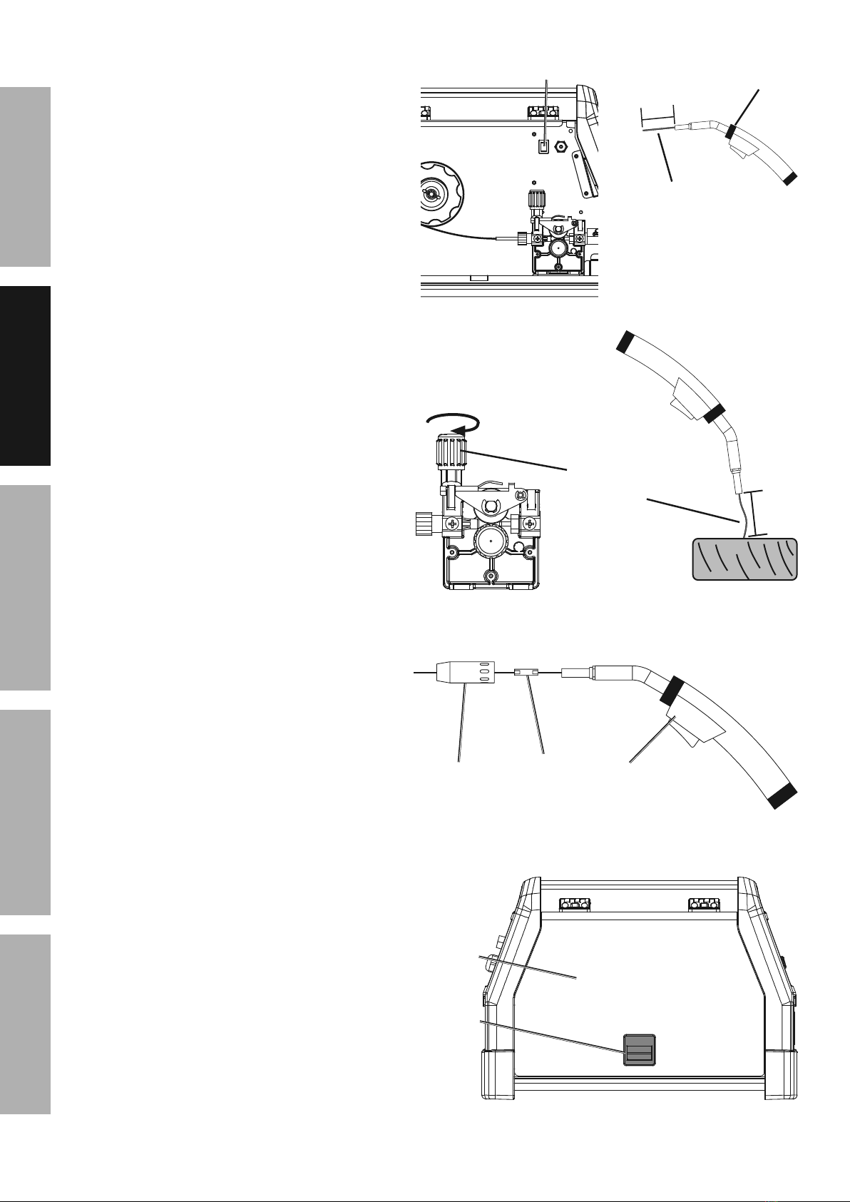
25. Set the MIG Flux / Spool Gun Switch
to MIG Flux Gun.
26. Point the Gun away from all objects.
Press and hold the Trigger until the wire feeds
through the end of the Gun two inches.
I(2&*.12&=.+21&;4X&:);2&)0/&*./(&/(2&*2=>.+9&
*.12,&&I(.'&.'&+)1;4=B&_0'/&/01+&)88&/(2&P2=>21&
4+>&60'(&/(2&*.12&=.+21&34:]&.+/)&/(2&S0+,
If the wire does not feed properly and
the Spool is stationary, turn OFF and
unplug the Welder and slightly tighten the
Feed Tensioner clockwise before retrying.
27. To check the wire’s drive tension, press and
hold Trigger to feed the wire against a piece of
wood from 2 to 3 inches away.
If the wire stops instead of bending,
unplug the Welder, slightly tighten the
Feed Tensioner clockwise, and try again.
If the wire bends from the feed pressure,
then the tension is set properly.
28. Turn OFF the Power Switch and unplug the
Power Cord from its electrical outlet.
29. Select a Contact Tip that is compatible with
the welding wire used. Slide the Contact
Tip over the wire and thread it clockwise into
the MIG Gun. Tighten the Contact Tip.
30. Replace the Nozzle and cut the wire
off at 1/2" from tip (1/2" stickout).
31. Close the Door. Make sure
Door is securely latched.
MIG Flux / &
G6))=&S0+&G*./:( KLS&S0+
P2=>.+9&
P.12
be
L+:12;2+/4==X&&
.+:124'2&/2+'.)+&&
0+/.=&&
*.12&32+>', baEe
M)[[=2 N)+/4:/
I.6 KLS&S0+
R))1&
Q4/:(
R))1
Page 15@)1&/2:(+.:4=&A02'/.)+'B&6=24'2&:4==&CD###DE#FDFEC#,Item 57863 57864
GH@<IJKHLMI<MHMN< OHGLN&P<QRLMSP<QRLMS&ILTG G<IUT
O4'.:&P2=>.+9
V24>&/(2&<MILV<&LKTWVIHMI&GH@<IJ&LM@WVKHILWM&'2:/.)+&4/&/(2&329.++.+9&)8&/(.'&;4+04=&
.+:=0>.+9&4==&/2\/&0+>21&'03(24>.+9'&/(212.+&328)12&*2=>.+9,
IW&TV<-<MI&G<VLWUG&LMcUVJ5&
T1)/2:/.Y2&9241&;0'/&32&*)1+&*(2+&0'.+9&/(2&P2=>21f&;.+.;0;&'(4>2&+0;321&CF&80==&84:2&'(.2=>&
(or welding mask), ear protection, welding gloves, sleeves and apron, NIOSH-approved respirator, and fire
12'.'/4+/&*)1]&:=)/(2'&*./()0/&6):]2/'&'()0=>&32&*)1+&*(2+&*2=>.+9,&&&
Q.9(/&81);&/(2&41:&:4+&:40'2&621;4+2+/&>4;492&/)&/(2&2X2'&4+>&'].+,&&
R)&+)/&3124/(2&41:&80;2',
Flux-cored wire welding is used to weld mild steel
and stainless steel without shielding gas.
MIG welding uses solid wire and shielding gas,
and is used to weld mild steel and stainless steel.
MIG welding can also be used to weld thinner
workpieces than flux-cored welding can.
Aluminum welding can be performed with an
optional Spool Gun (sold separately) using
aluminum wire and shielding gas.
Good welding takes a degree of skill and experience.
Practice a few sample welds on scrap before
welding your first project. Additional practice
periods are recommended whenever you weld:
• a different thickness of material
• a different type of material
• a different type of connection
• using a different process (MIG vs. Flux)
K4]2&614:/.:2&*2=>'&)+&6.2:2'&)8&':146&/)&614:/.:2&
/2:(+.A02&328)12&*2=>.+9&4+X/(.+9&)8&Y4=02,
IW&TV<-<MI&G<VLWUG&LMcUVJB&&
@LV<&HMR&OUVMG5&
Z226&*2=>.+9&/.6&:=241&)8&91)0+>2>&
)3_2:/'&*(2+2Y21&0+./&.'&6=0992>&
.+&4+>&/01+2>&)+,
T)*21&
W+
g
T14:/.:2&X)01&*2=>.+9&
/2:(+.A02&)+&':146&
6.2:2'&328)12&*2=>.+9&
4+X/(.+9&)8&Y4=02,
Altri manuali per MIG 170
1
Indice
Altri manuali Titanium Sistema di saldatura


