ANA-IOM-4.0 3-10-20
Single Duct Terminal Units Without Reheat
Thermostat Calibration Procedure
Press and hold both Up and Down arrows buttons for about 10
seconds until the display starts flashing “LIMITS”. Use Up or
Down arrow to display a flashing “SYSTEM”. Press “Set Point”
button. Select Sequence 01, SE01 and press “Set Point”
button, press Up or Down arrow to flashing “Exit”. Use Up or
Down arrows to navigate to “LIMITS” and press “Set Point”
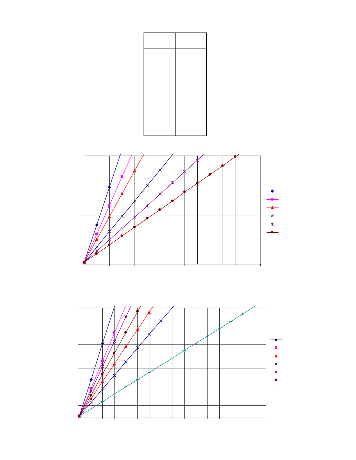
Button. Set cooling minimum by adjusting voltage for A01 MIN
corresponding to desired minimum flow volume from Figures 4
and 5. Set cooling maximum by adjusting voltage for A01 Max
corresponding to desired maximum flow volume from Figures 4
and 5.
Optional Morning Warm-Up (MWU) Operation
If this option has been ordered, the unit damper will drive full
open regardless of flow limit settings whenever supply air
temperature is above 80° F.
Check-Out Procedure
Push the Setpoint button (or either Up/Down button) to display
the current setpoint value. Use the Up/Down buttons to change
the value below room temp. Press the Setpoint button again,
and the thermostat will control at the new setpoint. Observe
damper movement. After a few minutes check to see that the
unit has reached maximum flow limit.
Single Duct Terminal Units with Reheat
Thermostat Calibration Procedure
Press and hold both Up and Down arrows buttons for about 10
seconds until the display starts flashing “LIMITS”. Use Up or
Down arrow to display a flashing “SYSTEM”. Press “Set Point”
button. Select Sequence 02 SE02 and press “Set Point” button,
press Up or Down arrow to flashing “Exit”. Use Up or Down
arrows to navigate to “LIMITS” and press “Set Point” Button.
Set cooling minimum by adjusting voltage for A01 MIN
corresponding to desired minimum flow volume from Figures 4
and 5. Set cooling maximum by adjusting voltage for A01 Max
corresponding to desired maximum flow volume from Figures 4
and 5. Set heating minimum by adjusting voltage for A02 MIN
corresponding to desired minimum flow volume from Figures 4
and 5. Set heating maximum by adjusting voltage for A02 Max
corresponding to desired maximum flow volume from Figures 4
and 5. If no Auxiliary Flow is desired, set A01 Aux to 0.
Check-Out Procedure
Push the Setpoint button (or either Up/Down button) to display
the current setpoint value. Use the Up/Down buttons to change
the snowflake/cool value above room temp. Press the Setpoint
button again, and the thermostat will control at the new
setpoint. Observe damper movement. After a few minutes
check to see that the unit has reached maximum flow limit.
Push the Setpoint button (or either Up/Down button) to display
the current setpoint value. Use the Up/Down buttons to change
the fire/heat value above room temp. Press the Setpoint button
again, and the thermostat will control at the new setpoint.
Observe damper movement. After a few minutes check to see
that the unit has reached minimum flow limit.
Single Duct Terminal Units with Heating/
Cooling Autochangeover(ACO)
Thermostat Calibration Procedure
Snowflake/cool is the cooling setpoint used to control damper
operation when supply air is below 70° F. Fire/heat is the
heating setpoint used to control operation when supply air is
above 80° F.Press and hold both Up and Down arrows buttons
for about 10 seconds until the display starts flashing “LIMITS”.
Use Up or Down arrow to display a flashing “SYSTEM”.
Press “Set Point” button. Select Sequence 02 SE02 and press
“Set Point” button, press Up or Down arrow to flashing “Exit”.
Use Up or Down arrows to navigate to “LIMITS” and press “Set
Point” Button. Set cooling minimum by adjusting voltage for
A01 MIN corresponding to desired minimum flow volume from
Figures 4 and 5. Set cooling maximum by adjusting voltage for
A01 Max corresponding to desired maximum flow volume from
Figures 4 and 5. Set heating minimum by adjusting voltage for
A02 MIN corresponding to desired minimum flow volume from
Figures 4 and 5. Set heating maximum by adjusting voltage for
A02 Max corresponding to desired maximum flow volume from
Figures 4 and 5. If no Auxiliary Flow is desired, set A01 Aux to
0.
Check-Out Procedure
With primary fan system supplying cold air (below 70°F), Push
the Setpoint button (or either Up/Down button) to display the
current setpoint value. Use the Up/Down buttons to change the
snowflake/cool value above room temp. Press the Setpoint
button again, and the thermostat will control at the new
setpoint. Observe damper movement. After a few minutes
check to see that the unit has reached maximum flow limit.
With primary fan system supplying hot air (above 80°F), Push
the Setpoint button (or either Up/Down button) to display the
current setpoint value. Use the Up/Down buttons to change the
fire/heat value above room temp. Press the Setpoint button
again, and the thermostat will control at the new setpoint.
Observe damper movement. After a few minutes check to see
that the unit has reached minimum flow limit.
Fan Powered Terminal Units without Heat
Thermostat Calibration Procedure
Press and hold both Up and Down arrows buttons for about 10
seconds until the display starts flashing “LIMITS”. Use Up or
Down arrow to display a flashing “SYSTEM”. Press “Set Point”
button. Select Sequence 01, SE01 and press “Set Point”
button, press Up or Down arrow to flashing “Exit”. Use Up or
Down arrows to navigate to “LIMITS” and press “Set Point”
Button. Set cooling minimum by adjusting voltage for A01 MIN
corresponding to desired minimum flow volume from Figures 4
and 5.
Optional Morning Warm-Up (MWU) Operation
If this option has been ordered, the unit damper will drive full
open regardless of flow limit settings whenever supply air
temperature is above 80° F.
Optional Night Shutdown (NSD) Operation
Units ordered with optional night shutdown (NSD) sequences
employ a differential pressure switch to sense loss of supply
duct static pressure. By this method, these units change
operating mode when the air handler fan is de-energized. If this
option has been ordered, the unit fan will de-energize
whenever the air handler unit (AHU) is off. If a minimum flow
limit has been set at the thermostat, the unit damper will drive
full open.
Optional Night Setback (NSB) Operation
Units ordered with optional night setback (NSB) sequences
employ a differential pressure switch to sense loss of supply
duct static pressure.