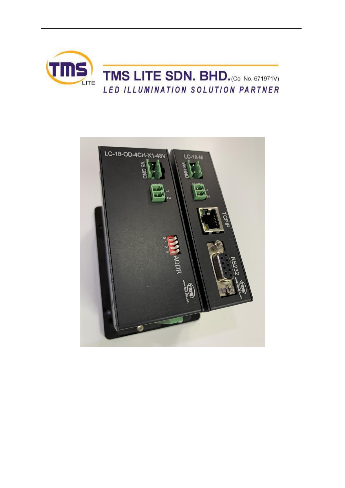
TMS Lite LC-18-OD-4CH-48V LIGHTING CONTROLLER UNIT
1
Table of Contents
Hardware ................................................................................................................................................2
Packing List..........................................................................................................................................2
General Description ................................................................................................................................3
Specification........................................................................................................................................3
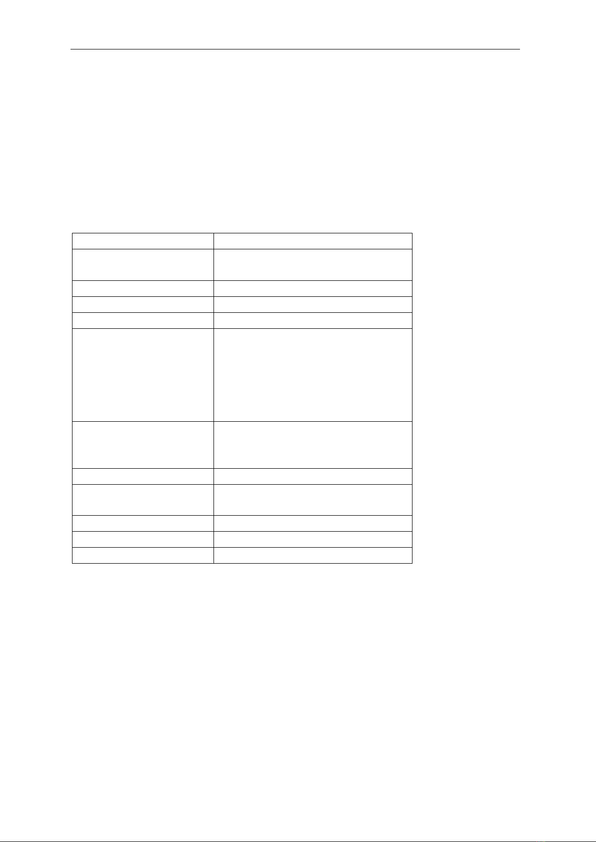
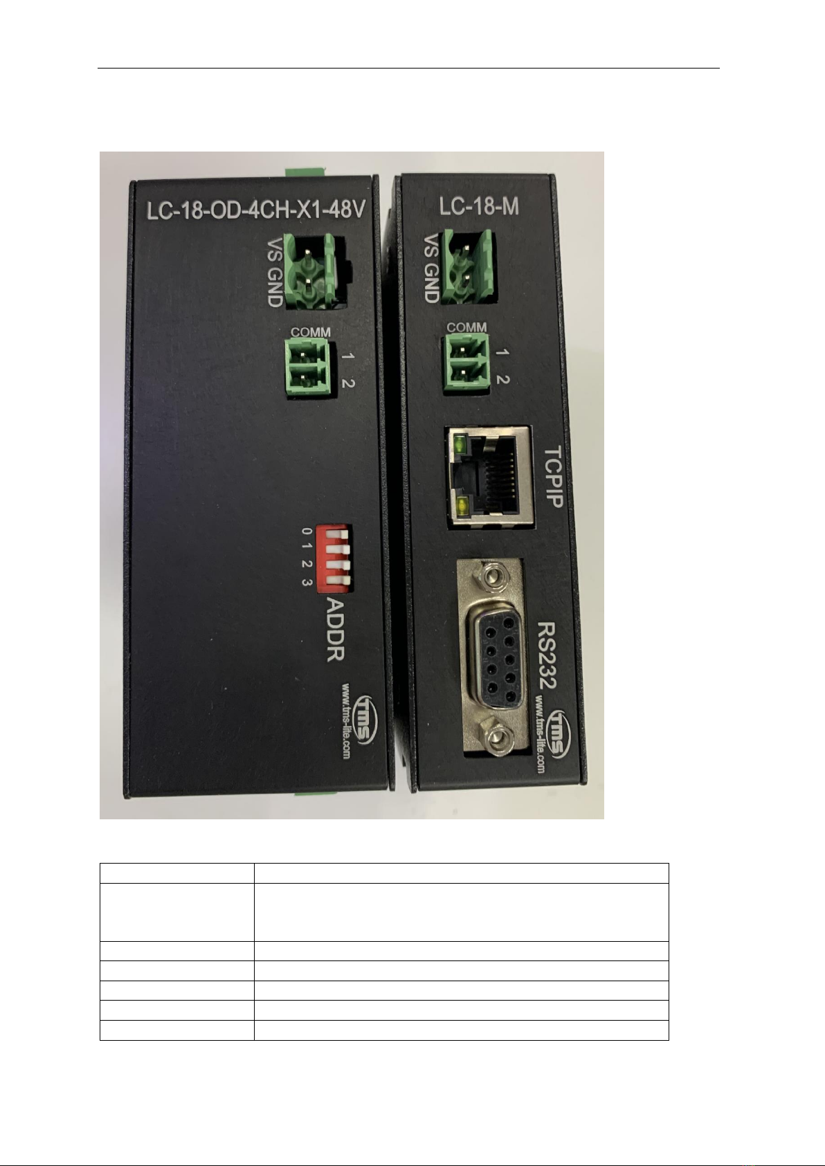
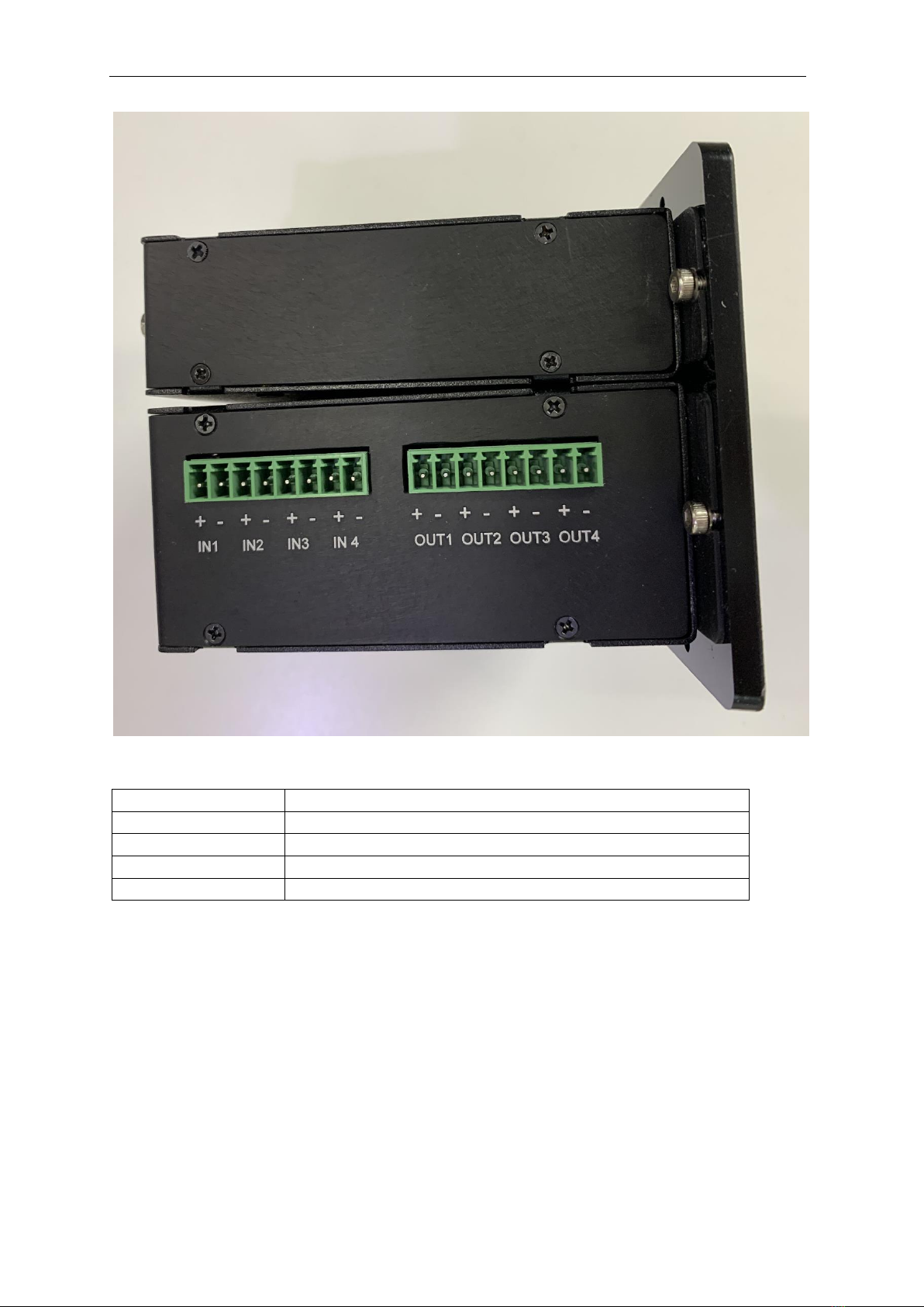
Connectors Description...........................................................................................................................4
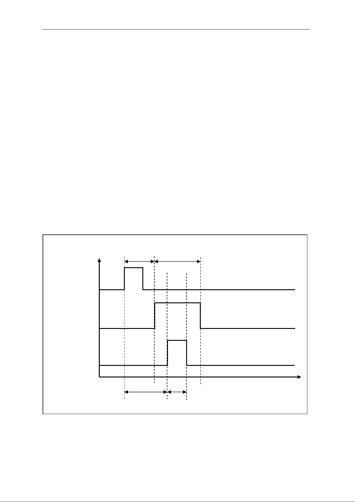
Operation Mode .....................................................................................................................................7
Strobe Mode .......................................................................................................................................7
Current Multiplier ...................................................................................................................................8
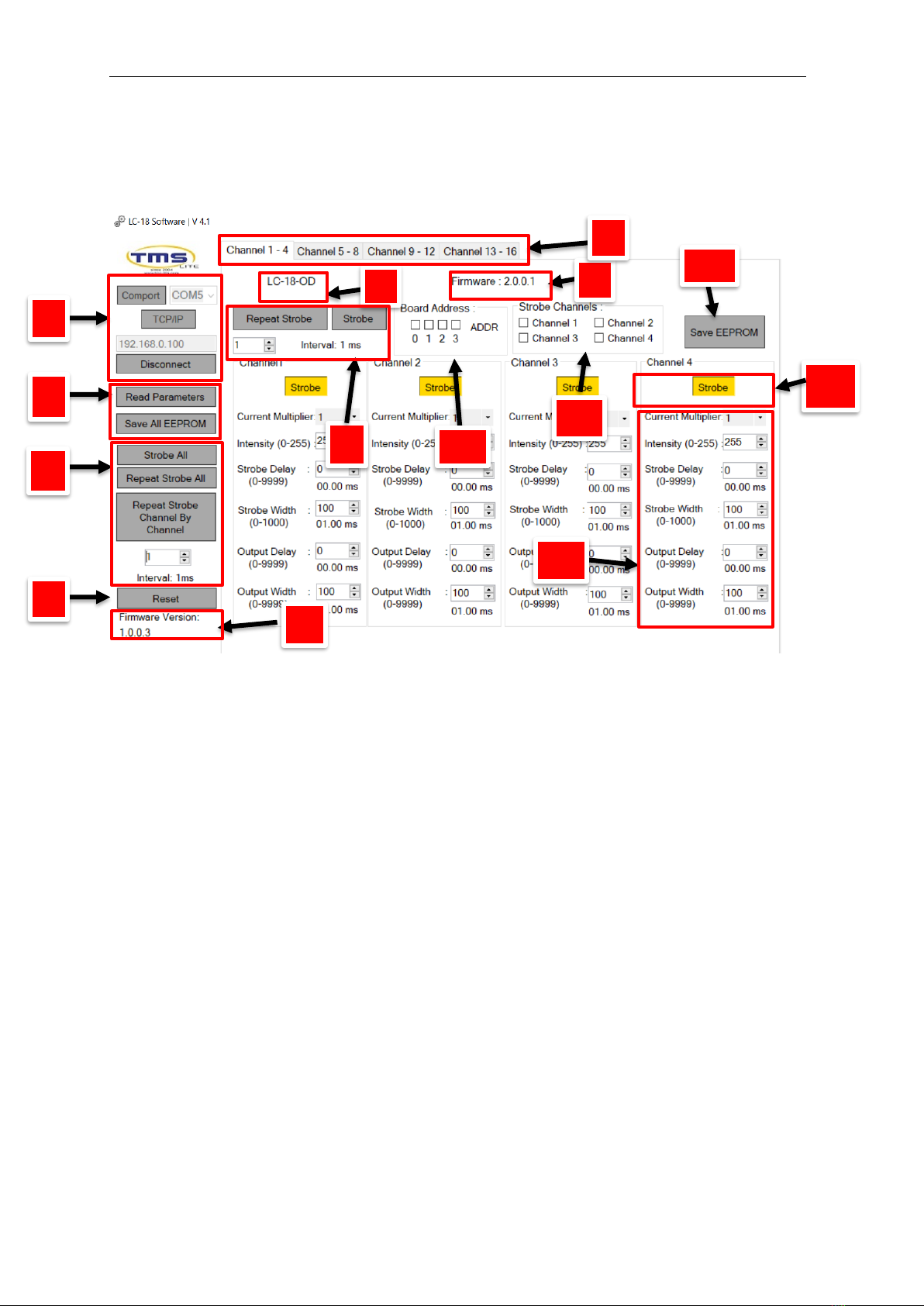
LC-18 Software........................................................................................................................................9
Change IP Address.................................................................................................................................11
Slave Board Address Setting .................................................................................................................12
Communication Connection .............................................................................................................13
Input Signal ...........................................................................................................................................14
Output Signal ........................................................................................................................................14
Accessories............................................................................................................................................15
24V Power Supply.............................................................................................................................15
48V Power Supply.............................................................................................................................16
Cable Selection..................................................................................................................................17
Cable Information .................................................................................................................................18
Power Cord Information .......................................................................................................................19
Drawing Dimension...............................................................................................................................20
Communication Protocol......................................................................................................................22
Revision Notes