Toro 03247 Manuale utente

FormNo.3430-932RevA
OperatorCoolingFan
Groundsmaster®orReelmaster®TractionUnitwithUniversal
Sunshade
ModelNo.03247
InstallationInstructions
Installation
LooseParts
Usethechartbelowtoverifythatallpartshavebeenshipped.
ProcedureDescriptionQty.Use
1Nopartsrequired–Preparethemachine.
2Nopartsrequired–Removethesunshade.
3Nopartsrequired–Installtheswitchpanelkit.
Longfan-mountbracket1
Coolingfan1
Shortfan-mountbracket1
Carriagebolt(1/4x5/8inch)4
Flangelocknut(1/4inch)4
Fanswitch1
Jamnut1
Knob1
Fan-speedcontroller1
4
Thread-formingscrew(#8x3/8inch)2
Installthecoolingfan,fan-speed
controller,andswitch.
Wireharness1
Cableties4
5Fuse(25A)1
Installthewireharness.
6Nopartsrequired–Connectthebattery.
7Nopartsrequired–Adjustthecoolingfanposition.
8Nopartsrequired–Installthesunshade.
©2019—TheToro®Company
8111LyndaleAvenueSouth
Bloomington,MN55420
Registeratwww.T oro.com.OriginalInstructions(EN)
PrintedintheUSA
AllRightsReserved*3430-932*A

1
PreparingtheMachine
NoPartsRequired
Procedure
1.Parkthemachineonalevelsurface.
2.Shutofftheengine,engagetheparkingbrake,
andremovethekeyfromtheignitionswitch.
3.Disconnectthebattery;refertotheelectrical
systemmaintenancesectionofyourOperator’s
Manual.
2
RemovingtheSunshade
NoPartsRequired
Procedure
g244329
Figure1
1.Sunshade
1.Removethe4ange-headbolts(5/16x1-1/4
inches)and4washers(5/16inch)thatsecure
thesunshadetotheside-framechannels(Figure
1andFigure2).
Note:Donotremovethegrommetsfromthe
sunshade.
g244328
Figure2
1.Grommet3.Washer(5/16inch)
2.Flange-headbolt(5/16x
1-1/4inches)
4.Clipnut(side-frame
channel)
2.Removethesunshadefromthemachine(Figure
1).
3
InstallingtheOptional
SwitchPanelKit
NoPartsRequired
Procedure
IftheoptionalSwitchPanelKitisnotinstalled,install
it;refertotheinstallationinstructionsfortheswitch
panelkit.
2

4
InstallingtheCoolingFan,
FanSwitch,andFan-Speed
Controller
Partsneededforthisprocedure:
1Longfan-mountbracket
1Coolingfan
1Shortfan-mountbracket
4Carriagebolt(1/4x5/8inch)
4Flangelocknut(1/4inch)
1Fanswitch
1Jamnut
1Knob
1Fan-speedcontroller
2Thread-formingscrew(#8x3/8inch)
InstallingtheCoolingFan
1.Locatethe2slotsinthecooling-fanhousing
closesttothefanharnesswiththe2-socket
connector(Figure3).
g244453
Figure3
1.2-socketconnector4.Slot(cooling-fanhousing)
2.Longfan-mountbracket5.Shortfan-mountbracket
3.Mountingtab
2.Insertthe2mountingtabsofthelongfan-mount
bracketintotheslotsinthefanhousing(Figure
3)thatyouidentiedinstep1.
3.Insertthe2mountingtabsoftheshortfan-mount
bracketintotheother2slotsinthecooling-fan
housing(Figure3).
4.Aligntheholesinthefanmountbracketstothe
holeintheswitchpanelasshowninFigure4.
g244454
Figure4
1.Flangelocknut(1/4inch)4.Carriagebolt(1/4x5/8
inch)
2.Longfan-mountbracket5.Frontofmachine
3.Switchpanel
5.Assemblethecoolingfanandbracketstothe
switchpanel(Figure4)with4carriagebolts(1/4
x5/8inch)and4angelocknuts(1/4inch).
6.Torquetheangelocknutsto1017to1243N∙cm
(90to110in-lb).
InstallingtheFanSwitch
1.Aligntheatontheoutershaftofthefan-switch
shaftwiththeD-shapedholeintheswitchpanel
(Figure5).
g244490
Figure5
1.Flat(fan-switchshaft)3.Knob
2.Jamnut4.D-shapedhole
3

2.Insertthefan-switchshaftthroughtheholein
thepanelandsecuretheswitchwiththejamnut
(Figure5).
3.AligntheD-shapedholeintheknobwiththeat
ontheinnershaftofthefan-switchshaft(Figure
5).
4.Presstheknobontotheswitchuntilknobisfully
seated(Figure5).
InstallingtheFan-SpeedController
1.Alignthefan-speedcontrollertotheangeof
thelongfan-mountbracketwiththeelectrical
terminalsaligntowardthebackofthemachine
(Figure6).
g244491
Figure6
1.Frontofthemachine3.Longfan-mountbracket
2.Fan-speedcontroller4.Thread-formingscrew(#8
x3/8inch)
2.Securethefan-speedcontrollertotheangeof
thelongfan-mountbracket(Figure6)withthe2
thread-formingscrew(#8x3/8inch).
5
InstallingtheWireHarness
andFuse
Partsneededforthisprocedure:
1Wireharness
4Cableties
1Fuse(25A)
InstallingtheWireHarness
1.Alignthewireharnessofthekittotheswitch
panelasshowninFigure7.
g244638
Figure7
1.Kit-wireharness
2.Connectthesocketterminalsofthekitwire
harnesstothebladeterminalsofthefan-speed
controller(Figure8)asshowninthefollowing
table:
WireHarness—WireColor
fortheSocketTerminals
Fan-Speed
Controller—BladeTerminal
Violet1—Low
Brown2—Medium
Orange3—High1
Optional4—High2
Pink5—Motor
4

g283647
Figure8
1.Violet(wire-harness
terminallabeledRESISTOR
MODULEL)
6.Bladeterminal5—Motor
(fan-speedcontroller)
2.Bladeterminal1
(Low—fan-speed
controller)
7.Pink(wire-harness
terminallabeledMOTOR
(+))
3.Bladeterminal2
(Medium—fan-speed
controller)
8.Orange(wire-harness
terminallabeledRESISTOR
MODULEH)
4.Bladeterminal3(High
1—fan-speedcontroller)
9.Brown(wire-harness
terminallabeledRESISTOR
MODULEM)
5.Bladeterminal
4—Optional(High
2—fan-speedcontroller)
3.Atthe20cm(8inch)branchofthekitwire
harness,connectthe2-socketconnectorinto
the2-pinconnectoroftheadapterwireharness
fortheswitchpanel(Figure9).
g244633
Figure9
1.2-socketconnector(20cm
(8inch)branch—kitwire
harness)
2.2-pinconnector(adapter
wireharness—switch
panel)
4.Connectthe5-pinconnectorofthefanswitch
intothe5-socketconnectorofthekitwire
harness(Figure10).
g244634
Figure10
1.5-socketconnector(kit
wireharness)
3.2-socketconnector
(cooling-fanharness)
2.2-pinconnector(kitwire
harness)
4.Fanswitch
5.Connectthe2-pinconnectorofthekitwire
harnessintothe2-socketconnectorofthe
cooling-fanharness(Figure10).
6.Securethewireharnesswiththe4cableties.
5

InstallingtheFuse
Insetthefuse(25A)intothefuseblockatthesecond
fuseslotfromtheleft(Figure11).
Note:Thefusemaynotneedtobeinstalledifafuse
hasalreadybeeninstalledfromanotherT orokit.
g244641
Figure11
1.Fuse(25A)2.Fuseslot—secondfrom
left(switchpanelfuse
block)
6
ConnectingtheBattery
NoPartsRequired
Procedure
Connectthebattery;refertotheelectricalsystem
maintenancesectionofyourOperator’sManual.
7
AdjustingtheCoolingFan
Position
NoPartsRequired
Procedure
1.Seattheoperatorofthemachineinthe
operator’sseat.
2.Rotatethefanswitchtomedium-fanspeed.
3.Determineiftheoperatorwantstheairstreamof
thecoolingfanmovedforwardorrearward:
•Iftheairstreampositioniscorrect,shutoff
thecoolingfan.
•Iftheoperatorwantstheairstreamofthe
coolingfanmoved,performthefollowing
steps:
A.Shutoffthecoolingfan.
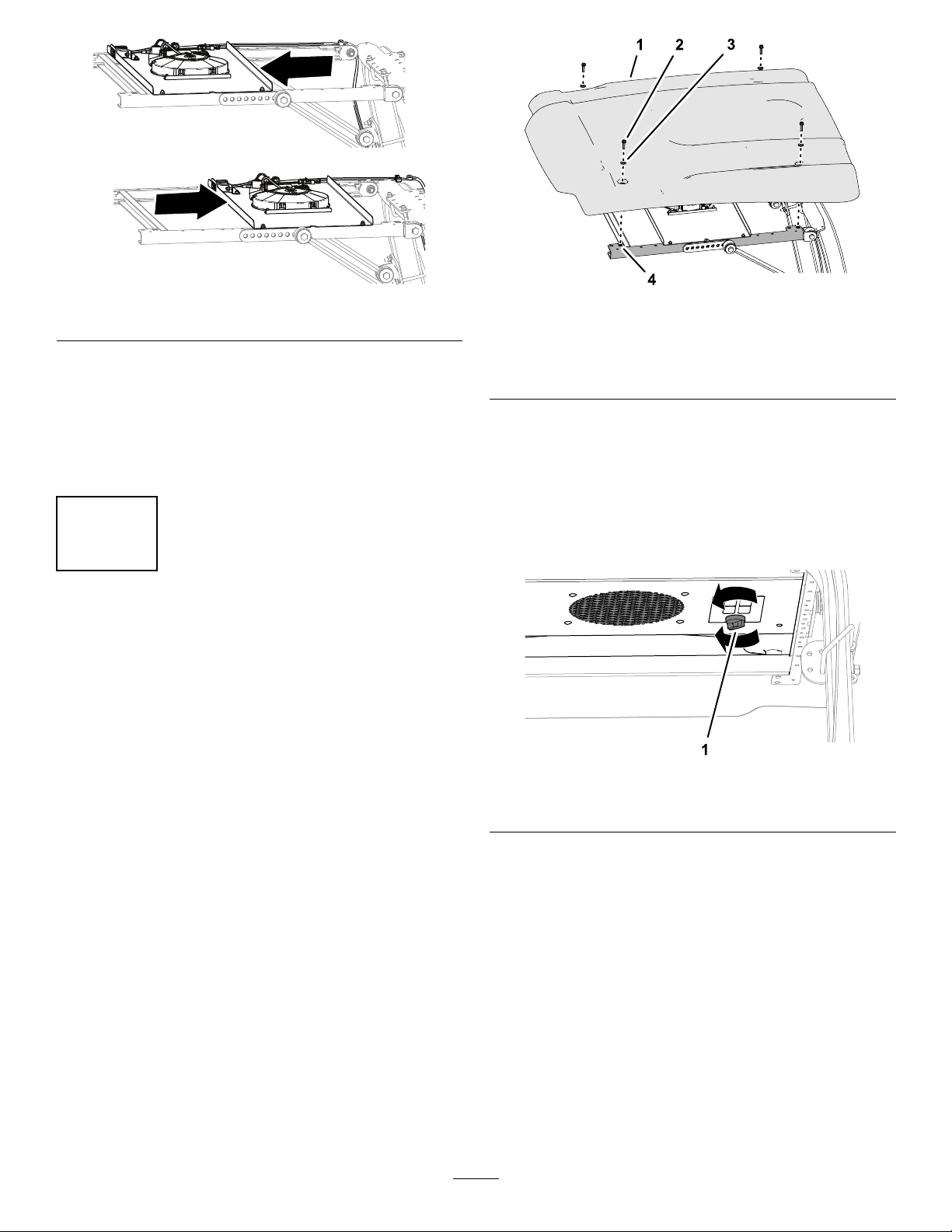
B.Removethe4carriagebolts(1/4x5/8
inch)and4angelocknuts(1/4inch)
thatsecuretheswitchpaneltotheleft
andrightside-framechannels(Figure
12).
g244667
Figure12
1.Flangelocknut(1/4inch)3.Carriagebolt(1/4x5/8
inch)
2.Switchpanel4.Side-framechannel
C.Movetheswitchpanelforwardor
rearward(Figure13)toalignthecooling
fanthepositionthatyoudeterminedin
step3.
Note:Youcansetthecoolingfanto1
of5positions.
6

g244666
Figure13
D.Assembletheswitchpaneltothe
side-framechannelswiththecarriage
boltsandlocknuts(Figure12)thatyou
removedinstep3B.
E.Torquetheangelocknutsto1017to
1243N∙cm(90to110in-lb).
8
InstallingtheSunshade
NoPartsRequired
Procedure
1.Aligntheholesinthegrommetsofthesunshade
withthe4clipnutsoftheside-framechannels.
2.Assemblethesunshadetotheframechannels
(Figure14)withthe4ange-headbolts(5/16x
1-1/4inches)and4washers(5/16inch)thatyou
removedin2RemovingtheSunshade(page2).
g244327
Figure14
1.Sunshade3.Washer(5/16inch)
2.Flange-headbolt(5/16x
1-1/4inches)
4.Clipnut(side-frame
channel)
3.Torquetheange-headboltsto1017to1355
N∙cm(90to120in-lb).
Operation
UsingtheCoolingFan
g244665
Figure15
1.Knob(fanswitch)
•T orunthecoolingfan,rotatetheknobforthe
fanswitchclockwisetotheLOW,MEDIUM,orHIGH
fan-speedposition(Figure15).
•T oshutoffthecoolingfan,fullyrotatetheknob
counterclockwisetotheOFFposition(Figure15).
7

DeclarationofIncorporation
TheToroCompany,8111LyndaleAve.South,Bloomington,MN,USAdeclaresthatthefollowingunit(s)
conform(s)tothedirectiveslisted,wheninstalledinaccordancewiththeaccompanyinginstructionsontocertain
ToromodelsasindicatedontherelevantDeclarationsofConformity.
ModelNo.SerialNo.ProductDescriptionInvoiceDescriptionGeneralDescriptionDirective
03247—OPERATORCOOLINGFANOPERATORCOOLINGFANOPERATORCOOLINGFAN2006/42/EC,
2014/30/EU
RelevanttechnicaldocumentationhasbeencompiledasrequiredperPartBofAnnexVIIof2006/42/EC.
Wewillundertaketotransmit,inresponsetorequestsbynationalauthorities,relevantinformationonthispartly
completedmachinery.Themethodoftransmissionshallbeelectronictransmittal.
ThismachineryshallnotbeputintoserviceuntilincorporatedintoapprovedT oromodelsasindicatedonthe
associatedDeclarationofConformityandinaccordancewithallinstructions,wherebyitcanbedeclaredin
conformitywithallrelevantDirectives.
Certied:AuthorizedRepresentative:
MarcelDutrieux
ManagerEuropeanProductIntegrity
ToroEuropeNV
Nijverheidsstraat5
2260Oevel
Belgium
JohnHeckel
Sr.EngineeringManager
8111LyndaleAve.South
Bloomington,MN55420,USA
February5,2019
Indice
Altri manuali Toro Hardware per computer
Manuali Hardware per computer popolari di altre marche

EMC2
EMC2 VNX Series Manuale del proprietario

Panasonic
Panasonic DV0PM20105 Manuale utente

Mitsubishi Electric
Mitsubishi Electric Q81BD-J61BT11 Manuale utente

Gigabyte
Gigabyte B660M DS3H AX DDR4 Manuale utente

Raidon
Raidon iT2300 Manuale utente

National Instruments
National Instruments PXI-8186 Manuale utente


