TracPhone V3 Manuale utente

Installation Guide
TracPhone®V3

Rubber Connector Washers
1
Addendum
PLEASE READ!
Important Addendum to the Installation Guide
Rubber connector washers are now provided in the kitpack to help
you protect the antenna’s RF connections from the elements.
To install these rubber washers, place them over the antenna’s “MTx”
and “MRx” connectors, as shown in Figure 1, before you connect the
RG-11 cables. Then, when you connect and tighten the RG-11 cables,
be sure the washers compress against the antenna’s baseplate.
Figure 1 RG-11 Cable Connection to the Antenna
The integrity and reliability of the RF cables and their connections
are critically important. Make certain that these cables are properly
terminated, sealed against seawater and corrosion, strain-relieved,
protected from abrasion, and free of stress. Refer to the Installation
Guide for details.
IMPORTANT!
Antenna Baseplate
Rubber Washer
Apply Silicone Grease
RG-11
54-0842 Rev. A

AC Power and Grounding Requirements
1
Addendum
PLEASE READ!
Important Addendum to the Installation Guide
The KVH antenna system is AC powered, just like the other onboard
equipment to which it connects. Therefore, installing the system
requires careful examination of the AC power and grounding onboard
the vessel.
Figure 1 AC Power Options
KVH Antenna System
KVH Antenna System
Ground
50-120 VAC
Shipboard
Two-Phase,
Split-Phase,
or Delta Power
50-120 VAC
Leakage Current
KVH Antenna System
Shipboard
3-Wire
Single-Phase
AC Power
Ground
Neutral
N
100-240 VAC
OR
OR
Ground
Neutral
N
100-240 VAC
Single-Phase
Power Input
Ground Fault
Monitor
(when required)
Isolation Transformer
Ground
Ground
50-120 VAC
50-120 VAC
Shipboard
Two-Phase,
Split-Phase,
or Delta Power
54-0831 Rev. A

AC Power and Grounding Requirements
2
Addendum
AC Power Requirements
The KVH antenna system is designed to run on 3-wire single-phase
AC power (hot, neutral, and ground). Voltage between hot-neutral
and hot-ground should each measure between 100-240 VAC.
Many large ships use two-phase, split-phase, or delta power instead
(3 wires: hot, hot, and ground; no neutral). In this case, voltage
between hot-hot measures the proper voltage (100-240 VAC); while
hot-ground measures only half the voltage (50-120 VAC). Although
KVH antenna systems can operate on this type of power, the excess
voltage present on the second phase will cause a small amount of
current to leak onto ship's ground. This leakage current might be
unacceptable on some vessels. So be sure to check with the customer
or ship's electrician and get permission before you run the antenna
system on two-phase power. Also be sure to ground the system, as
explained on the next page.
If two-phase power is the only available power source onboard, and if
leakage current is unacceptable, KVH recommends that you install a
suitable isolation transformer to supply single-phase power to the
antenna system and run a ground wire from the transformer to ship's
ground. In addition, since ground fault protection devices cannot
detect faults behind a transformer, you will also need to install a
ground fault monitoring device between the isolation transformer and
the antenna system if ground fault protection is required on the vessel.

AC Power and Grounding Requirements
3
Addendum
Grounding Requirements
Proper grounding of the antenna system to ship's ground is critically
important, as it protects the equipment from lightning and
electrostatic discharges (ESD). Failure to ground the chassis of the
antenna's control unit risks damage to the antenna and electric shock.
In a standard installation with a connection to single-phase AC power,
the antenna system is normally connected to ship's ground through
the ground wire of the antenna control unit's power plug. As an
alternative, you may run a separate ground wire from the antenna
equipment's chassis to ship's ground, or mount the equipment within
a grounded equipment rack.
You are responsible for the quality and safety of the system’s
installation. Be sure that it meets these critical power and grounding
requirements.
WARNING
Failure to ground the antenna system properly to ship’s ground
will cause an unsafe floating ground condition, risking damage to
the antenna and electric shock, potentially resulting in DEATH.
In a floating ground condition, the difference between the
equipment’s chassis ground and the ship’s ground can measure
well over 100 volts, when it normally should not exceed 25 volts.
Therefore, always measure the difference in potential between
chassis ground and ship’s ground to make certain that there is no
dangerous floating ground condition, even if the ground pin of the
vessel’s AC power plug appears to be intact.
RF Cable Tool Kits
1
Addendum
PLEASE READ!
Important Addendum to Your Product Manual
KVH now includes a torque wrench and silicone grease with the
LMR-400-75 and LMR-600-75 RF cable termination tool kits. The
torque wrench is set to 20 in.-lbs, which KVH has found to be the ideal
torque for external RF cable connections.
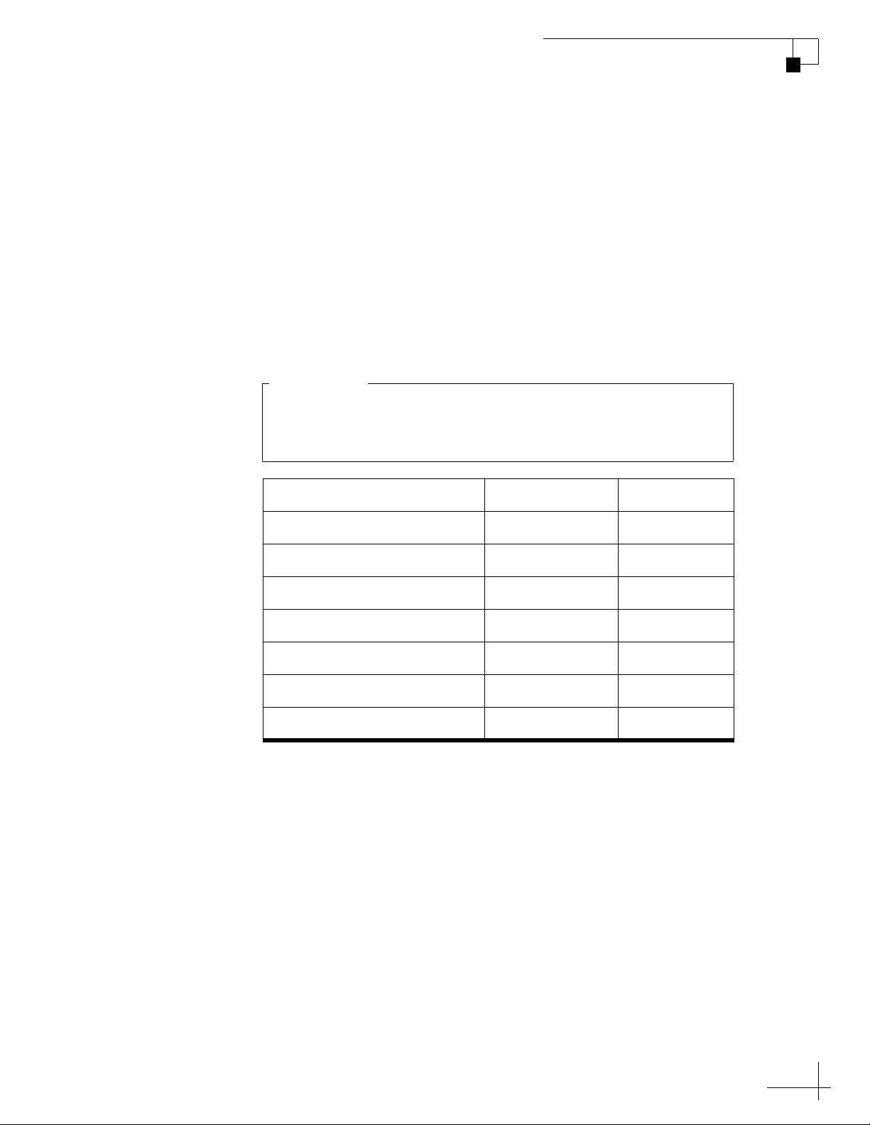
The table below lists the updated part numbers for these tool kits, as
well as the associated RF cables.
Item KVH Part # Length
One RG-11 cable (for V3) 32-1087-50 50 ft (15 m)
One RG-11 cable (for V7) 32-0566-50 50 ft (15 m)
RG-11 tool kit 72-0493 N/A
One LMR-400-75 cable 32-0944-0100 100 ft (30 m)
LMR-400-75 tool kit 72-0374-75 N/A
One LMR-600-75 cable 32-0945-0150 150 ft (45 m)
LMR-600-75 tool kit 72-0375-75 N/A
You need to run two RF coax cables (transmit and receive) for
every TracPhone antenna installation, so be sure to order a
quantity of two cables for a new installation.
IMPORTANT!
54-0815 Rev. A

RF Cable Connectors
1
Addendum
PLEASE READ!
Important Addendum to Your Product Manual
A small packet of silicone grease is supplied in the kitpack. Apply this
grease to the inner body of all RF cable connectors that you connect to
the KVH antenna and any inline feed-thru adapters above deck. This
grease will help prevent moisture from seeping into or forming inside
the connector and protect the center conductor from corrosion.
Figure 1 Silicone Grease
Directions for Use
When connecting RF cables above deck to the KVH antenna, as well as
to any inline feed-thru adapters, follow the steps below to protect and
seal each connection:
1. Clean and dry the male connector on the RF cable and the
female connector on the antenna or feed-thru adapter.
2. Fill half of the inner body of the RF cable’s connector with
silicone grease. Connecting the cable in the next step will
displace the grease to fill the entire space within the connector.
3. Connect and SLOWLY hand-tighten the RF cable to the
antenna or feed-thru adapter, allowing the grease to diffuse
and settle into the entire connector body.
4. Make sure the RF cable’s connector is tightened all the way
into the female connector of the antenna or feed-thru
adapter. Then tighten the connection with a 7/16" torque
wrench set to in.-lbs.
5. Wipe off any excess grease from the outside of the
connector.
6. Seal the connection with silicone sealant, self-vulcanizing
tape, or equivalent. If using self-vulcanizing tape, be sure to
wrap the tape CLOCKWISE around the connector (the
same direction in which you tightened the connector). Wrapping
the tape in the opposite direction will result in tension that
might loosen the connector over time.
The procedure is complete.
54-0779 Rev. A
TracPhone V3 Installation Guide
1
KVH’s Compact mini-VSAT Broadbandsm System
KVH, TracPhone, and the unique light-colored dome with dark contrasting baseplate are registered trademarks of KVH Industries, Inc.
mini-VSAT Broadband is a service mark of KVH Industries, Inc. All other trademarks are property of their respective companies.
The information in this document is subject to change without notice. No company shall be liable for errors contained herein.
© 2011 KVH Industries, Inc., All rights reserved. 54-0747 Rev. B
These instructions explain how to install the TracPhone V3 mini-VSAT Broadband satellite
communications system. Instructions on how to use the system are provided in the User’s Guide.
Installation Steps
CAUTION - RF Radiation Hazard
Who Should Install the System?
To ensure a safe and effective installation, only a KVH-certified technician should install the
TracPhone system. To find a technician near you, visit www.kvh.com/wheretogetservice.
Technical Support
1. Inspect Parts and Get Tools ................. 3
2. Plan the Antenna Installation.............. 4
3. Plan the Belowdecks Installation ........ 5
4. Prepare the Belowdecks Units............. 6
5. Prepare the Antenna Site...................... 9
6. Remove the Shipping Restraints....... 10
7. Prepare the RF Cables......................... 11
8. Wire the Antenna ................................ 12
9. Mount the Antenna............................. 14
10. Wire the Belowdecks Units.................15
11. Connect Power......................................17
12. Configure the Computer(s).................18
13. Turn On the System .............................21
14. Update the System Software...............22
15. Set Up RF Hazard Zones.....................23
16. Test the System.....................................24
17. Educate the Customer..........................25
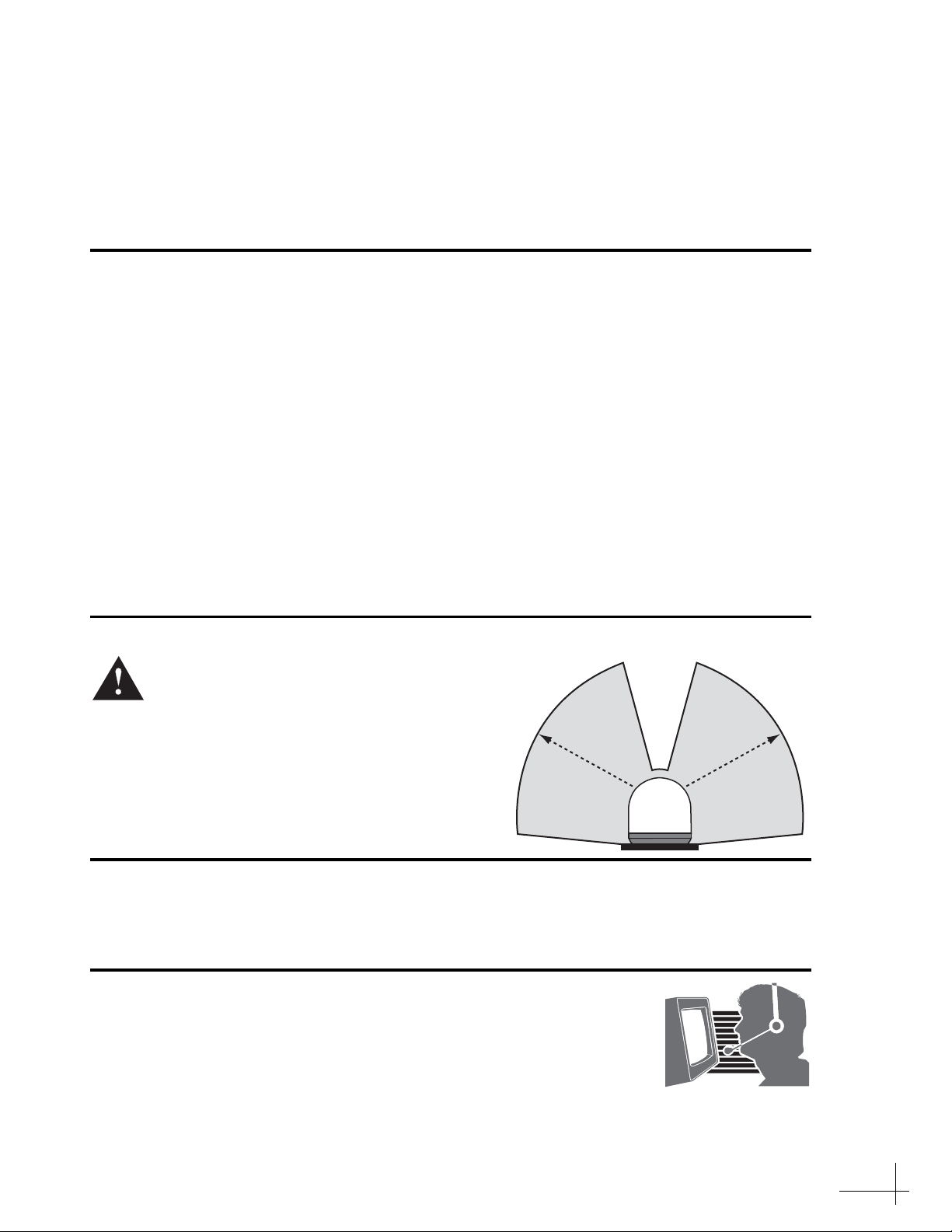
The antenna transmits radio frequency (RF)
energy that is potentially harmful.
Whenever the system is powered on, make
sure everyone stays more than 32 ft (10 m)
away from the antenna within its 7.5-75°
elevation range. No hazard exists directly
above the antenna and anywhere below the
antenna’s mounting plane.
North/South America, Australia:
Phone: 1 866 701-7103 (U.S. only)
Phone: +1 401 851-3806
E-mail: [email protected]
Europe, Middle East, Asia, Africa:
Phone: +45 45 160 180
E-mail: [email protected]
Radiation
Hazard
3
2
ft (10
m)
7.5°
Radiation
Hazard
32
ft
(
10
m)
75°75°
7.5° Antenna

3
Before you begin, follow these steps to make sure
you have everything you need to complete the
installation.
a. Unpack the box and ensure it contains
everything shown in Figure 1 and on the
Kitpack Content Lists. Save the packaging for
future use.
b. Carefully examine all of the supplied parts to
ensure nothing was damaged in shipment.
c. Gather all of the following tools and
materials that you will need:
• Flat-head and Phillips-head screwdrivers
• Electric drill and 5/16" (8 mm) bit
• 3.5" (89 mm) hole saw
• 1/2" socket and 7/16" socket
• 7/16" open-end wrench and 7/16" torque
wrench set to 20 in.-lbs
• Light hammer and center punch
• Adhesive tape and scriber or pencil
• Silicone sealant or equivalent
• Wire strippers and terminal lug crimper
•Two75RF coax cables, “F” connectors,
and associated installation tools (see
page 11)
•Windows
®7, Vista™, or XP laptop with
the latest version of TracPhone V-series
Flash Wizard installed (software available
to technicians on the KVH Partner Portal)
• Isolation transformer, if required (see
page 17)
Radome
Baseplate
Figure 1: TracPhone V3 System Components
Antenna
Control Unit
Modem
Ethernet Switch Multimedia Terminal
Adapter (MTA)
(KVH part #02-1860)
(KVH part #02-1601-02)
(KVH part #19-0487)
(KVH part #19-0729) (KVH part #19-0504)
(KVH part #72-0485)
Always lift the antenna by the baseplate and
never by the radome or any portion of the
internal antenna assembly (see Figure 1).
IMPORTANT!
Inspect Parts and Get Tools
1

4
Before you begin, consider the following antenna
installation guidelines:
• Minimize blockage. The antenna requires a
clear view of the sky to transmit and receive
satellite signals (see Figure 2). The fewer
obstructions, the better the system will
perform.
• Make sure the mounting surface is wide
enough to accommodate the antenna’s base
(see Figure 3). Also make sure it is flat, level,
strong enough to support the antenna’s
weight (25 lbs, 11.3 kg), and rigid enough to
withstand heavy vibration.
• Select a location that is as close as possible to
the intersection of the vessel’s centerline and
midships.
• Select a location that is well above any areas
accessible to passengers and crew to reduce
the risk of RF radiation exposure.
• Avoid placing the antenna near any magnetic
compasses or other onboard antennas to
prevent potential interference.
Blocked!
Antenna
Mast
Look Angle
Vessel Platform
7.5° to 75°
Figure 2: Blockage from Obstruction
FWD
17.6"
(447.1 mm)
15.5"
(393.7 mm)
9.2"
(233.7 mm) 4.6"
(116.8 mm)
5.6"
(142.2 mm)
2.8"
(71.1 mm)
4 x Ø.31"
(Ø7.9 mm)
Side View
Bottom View
Figure 3: Antenna Dimensions
Do not mount the antenna at the same level as
the radar because the radar’s energy can
overload the antenna and damage its internal
components. Ideally, you should mount the
antenna 4 ft (1.2 m) above the radar, outside
the beam path of the radar.
IMPORTANT!
Plan the Antenna Installation
2
Altri manuali per V3
1
Indice
Altri manuali TracPhone Antenna

Manuali Antenna popolari di altre marche

Alfa Network
Alfa Network APA-L01 Manuale utente

Naval
Naval PR-422CA Manuale utente

Feig Electronic
Feig Electronic ID ISC.ANTH200/200 Series Manuale utente

TERK Technologies
TERK Technologies TV44 Manuale utente

Directive Systems & Engineering
Directive Systems & Engineering DSE2324LYRMK Manuale utente

HP
HP J8999A Manuale utente


