TraffiCalm M75-SPTOP-000S Manuale operativo

Important Information
Your guide to install and
connect a TraffiCalm Top of Pole
Solar Power Kit
Applies to:
M75-SPTOP-000S
M75-SPTOP-000C
M75-SPTOP-000N
PN: 029-05280-0000 rev A
5676 E. Seltice Way
Post Falls, Idaho 83854
1.855.738.2722 | www.trafficalm.com
PG 2
<Intro>
Fast Facts - If you read one thing, let this be it.
• This system is supplied as a complete kit to
provide 12V power to a TraffiCalm device
• This design is specifically designed for mounting
to the top of a 4.5” (OD) round post. If you’ve
spec’d some other post, this kit was mis-ordered
• TraffiCalm has made every effort to supply the
hardware necessary to install this kit to most
standard road-side installations. However, it may
be necessary to source other components (not
included) for the variety of installations this kit
could apply to.

PG 3
<Intro>
What’s included?
Solar Panel and Mount
• A 60W, 100W, or 150W solar panel (depending on
what was ordered)
• qty 1 NPT/SAE threaded 1-1/2” post extension
• qty 2 single threaded 1-1/2” support pipes
• qty 1 x-pipe fitting
• qty 2 Pelco end caps
• qty 1 x-pipe threaded cap (aluminum)
• qty 2 standard drilled channel brackets
• qty 3 NPT threaded lock rings
• qty 2 serrated pipe clamp assemblies
• qty 1 Post Top Hub with lock ring
• Assorted assembly hardware
• Wiring harness, panel to controller
• qty 2 weather tight wiring seals
• Solar Controller (applies to 100 and 150 Watt
models only)
Battery and Control Cabinet
• Qty 1, 2, or 4 35Ah AGM Batteries
• Powder coated enclosure
• Enclosure to post mounting bracket
• Sunsaver 10L or 20L Charge Controller
• Wiring harness
PG 4
<Panel Bracket>
Before Assembly...
Ensure all set screws and lock rings are loosened or
removed. Irreparable thread damage can occur if set
screws are left exposed in the thread.
They will all be used later, so don’t dispose of them!
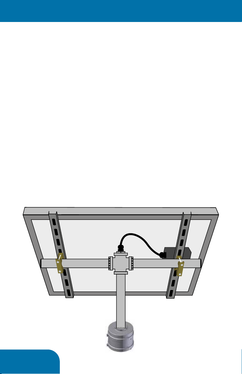
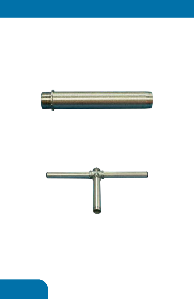
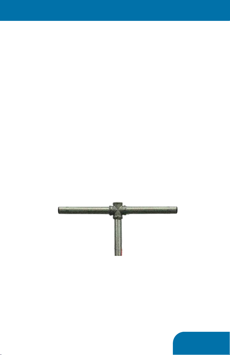
Assemble the Post Top Bracket
1. On all three pipe extensions install lock rings to
the straight cut threads (SAE), as seen below
2. Fully thread the two single threaded pipes to the
x-pipe fitting, directly across from one another, as
sen below.
3. Fully thread the straight threaded (SAE) side of
the double threaded pipe to the x-pipe fitting at a
90°angle to the pipes assembled in step 1, result
seen below
4. Across the bracket from this pipe, install the
x-pipe threaded cap, fully seat it in the x-pipe
5. It is now okay to tighten the lock rings and set
screws on this assembly, no further adjustment
will be required
This assembly provides the structural support to the
solar panel. It is important that all parts be threaded
and tightened sufficiently.
PG 5
<Prep Panel>
Before Assembly...
Following this sequence is critical. There are com-
ponents that cannot be accessed past other install
steps if done out of order.
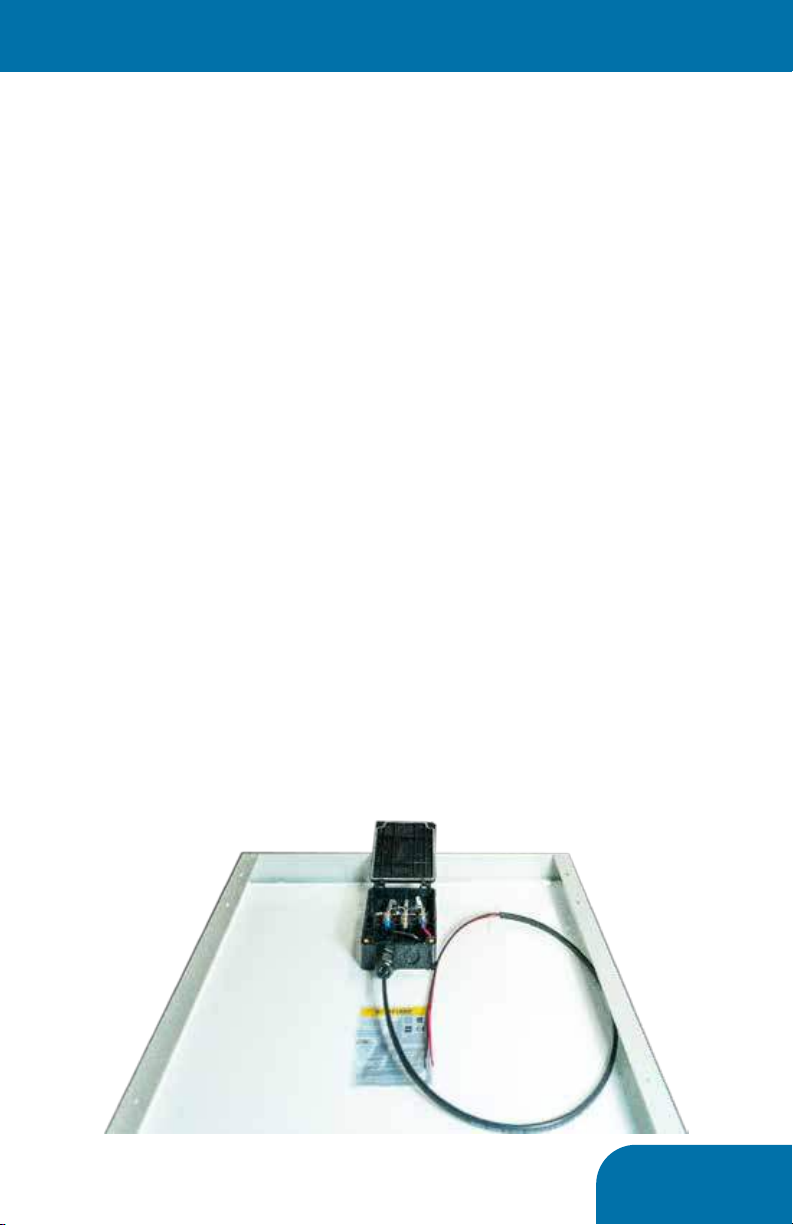
Assemble the Panel Wiring Harness
The panel harness features a single cable consisting
of two wires- red and black. The wiring harness
features fast connections at the panel end to
expedite installation.
1. Unless already done, remove one full tapout
from the bottom of the junction box with a flat
screwdriver and hammer to accommodate cable
ingress
2. Open the panel’s junction box to access the
wiring location terminals
3. Install one side of the length of conduit to box
4. Each panel is different, and suppliers change the
connection methods regularly. But in general
connect the black wire as far left as possible, and
the red wire as far right as possible. Supplemental
guides will be provided where needed
5. Allow the harness to hang loosely and proceed
PG 6
<Prep Panel>
Assemble the mounting structure to the panel
The mounting structure features basic hardware
components assembled to the panel’s frame, and
integrates the frame for support.
1. Assemble qty 4toothed clamps to universally
drilled cross supports with four 3” long x 1/4” bolts
and four 1/4” nuts.
2. Assemble the qty 2 universally drilled supports
across the height of the panel as shown below
3. The cross support bolts can be fully secured to
the solar panel frame. The nuts are sprung to
assist with assembly, so ensure the spring is fully
compressed and the bolt is tightened sufficiently
to prevent loosening.
4. Do not assemble the panel to the support
structure yet.
PG 7
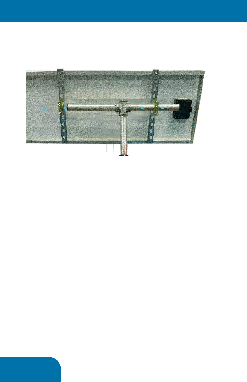
<Assemble To Post>
A Note Before Proceeding...
We recommend that as much assembly be
accomplished on the ground before hoisting the
assembly up on the pole. We have determined that
at this point the solar panel is ready to be mated to
the SlimLine Controller or Collaborator Hub already
installed on the pole. If circumstances would benefit
from more assembly before mating to the pole,
proceed at your own discretion.
Mating the mounting structure to the pole top hub
(Controller or Collaborator)
The mounting structure is supported by the double-
threaded pipe assembled on page 4. This will
thread into the pole top Hub. As mentioned before,
loosen the set screw on the Hub before affixing the
structure.
Thread the assembly to the Hub as much as possible.
The result will appear as seen below. Do not tighten
the set screw just yet.
PG 8
<Assemble To Post>
Mating the solar panel to the mounting structure
1. With the serrated clamps fully assembled, but
loose, slide one side onto one side of mounting
structure as shown below
2. Slide the panel the opposite direction to capture
both serrated clamps on the mounting structure’s
horizontal pipes
3. Tighten all bolts just tight enough to allow for
adjustment, but not slack.
4. To maximize solar panel aiming consider the
following best practices
• The angle of the panel should equal the geographical
latitude of the installation
• The panel should face geographical (not magnetic)
south
• If heavy snow cover is expected a steeper angle may be
more effective beyond matching the latitude
• If shadowing is expected throughout the day, rotating
the panel toward the best exposure to sunlight is
advisable.
Making sure it performs for years to come...
1. With the panel aimed as best as possible,
all the clamps and set screws previously left
loose can be tightened to prevent movement,
especially consider loosening from wind.
12
PG 9
6
3Installation Requirements
This section describes the components, tools, and
information you must have available before
installing TraffiCalm 140Ah Solar Kit.
3.1
Equipment Requirements
In addition to the Driver Feedback Sign to be
installed, you will need the following suggested
items if you intend to follow these directions:
oPole and Footing material
oStainless steel banding and banding clips and
application tool or adjustable steel banding
for installing Battery Box & Sign
oAssorted hand tools.
oSocket set and drive handle.
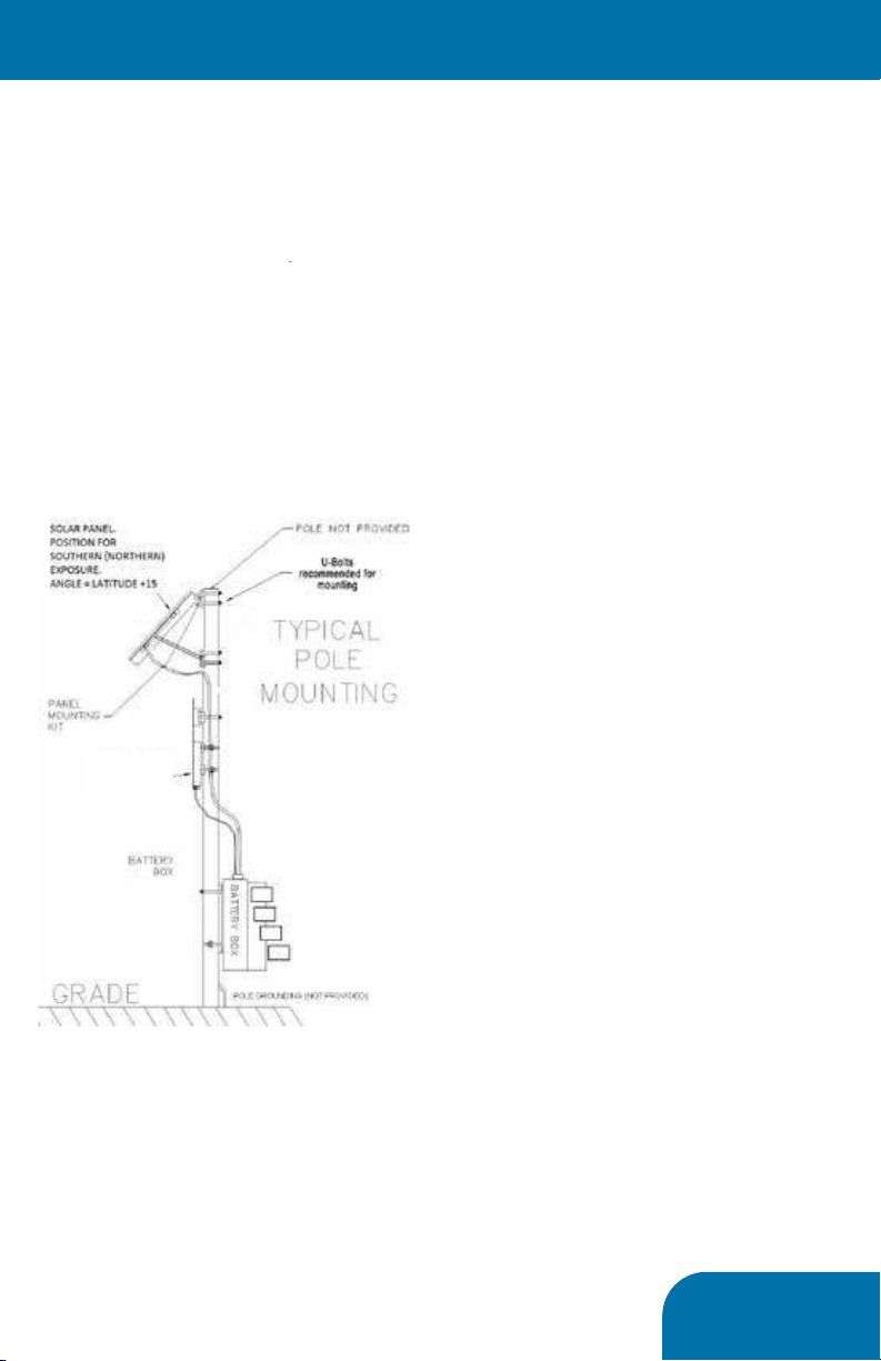
oU-Bolts for installing solar panel
3.2
Installation of Solar Panel
NOTE
It is the installer’s responsibility to
ensure that this installation
complies with local and national
codes.
Use a pole of proper size with an appropriate footing
for the soil and load conditions. Consult with a
professional Civil engineer for proper pole selection
and footing design for the local area. Assemble
the solar panel mounting bracket using directions
supplied with the mounting bracket components.
Install the mounting bracket onto the pole with user
supplied (U-Bolts).
In northern latitudes aim the bracket at true South,
not magnetic south. True South is the direction
facing the sun parallel to the shortest shadow of the
day cast by the sign pole, which occurs at “Solar
Noon”. To estimate what time solar noon will occur
in your area go to the NOAA web site with your
longitude and latitude.
http://www.srrb.noaa.gov/highlights/sunrise/sunrise.h
tml
Set the bracket angle using your current latitude +15
degrees as measured from horizontal (flat) to the final
position. Example: If the latitude is 45-degrees, set
the panel angle 60-degrees away from flat. You may
be able to get a small amount of additional power by
calculating the set angle using: Latitude *0.9 +29.
This results in a steeper angle than the other method,
optimizing collection around the noon hours during
the winter months, which is when the most solar
energy is available.
Install the solar panel onto the mounting bracket.
3.3
Battery Box Installation
Note: you may wish to cover the solar panel during
daylight installation to prevent accidental short
circuit of energized panel during installation.
Attach the “I” bracket to the battery box using
the included hardware.
a. Attach the “I” bracket to the center holes of
the battery box using two 3/8-16 x 1-1/4 inch
bolts, two 3/8-inch flat washers, and two
lock washers. (These bolts are hidden when
the battery box is mounted on the pole.)
b. Install 3/8-16 x 1-inch bolts in the remaining
four holes of the bracket with a flat washer
and a lock washer on each bolt.
Attach the battery box to the pole with user-
supplied 3/4-inch banding and a buckle in two
places (as close to each cross arm of the bracket
as possible).
Connect battery power to the Electronic Control
System (ECS) see Figure 3-1 (15” DFB ECS
35Ah, 70Ah, and 140Ah Solar Kits.
12V Radar Speed Sign
Radar
Speed Sign
Battery box may
include up to 4
batteries
<System Assembly>

PG 10
8
b. Connect the solar panel red wire to the
positive (+) terminal of the solar charger “SOLAR +”
terminal (4).
c. Connect the solar panel black wire to the
solar charger “SOLAR –“ terminal (3).
Check the panel operation and battery charging using
a volt meter. During daylight hours, if the battery
voltage rises above night levels, then the solar panel
and charger are working.
Monitor the charge process through a full charge. If
the charge voltage is excessive, then the charger may
have failed and will damage the batteries unless
action is taken to disconnect the solar panel until
repairs are made.
The charger is temperature compensated. It is
normal for the charge voltage to be higher when the
weather is cold, and lower when the weather is hot.
The normal full charge voltage varies -28mV per
degree C of deviation from 25°C.
Note: The solar panel only provides power
when illuminated by the sun. If the panel was
covered during installation, remove the cover
before performing this test.
For best results, start with a new fully charged
battery. Never mix old and new batteries. Be sure
to ground the solar panel rack and battery box
properly according to code.
8
c. Connect the battery box red wire (+) to the
panel + on the solar panel terminal block.
Connect the battery box black wire to panel
negative in the panel terminal block.
8. Connect the solar panel wires to the solar
charger in the battery box. See Figure 3-3.
a. Make sure the opaque cloth is still covering
the panel.
b. Connect the solar panel red wire to the
<System Assembly>
Questo manuale è adatto per i seguenti modelli
2
Manuali Antenna popolari di altre marche

Alfa Network
Alfa Network APA-L01 Manuale utente

Naval
Naval PR-422CA Manuale utente

Feig Electronic
Feig Electronic ID ISC.ANTH200/200 Series Manuale utente

TERK Technologies
TERK Technologies TV44 Manuale utente

Directive Systems & Engineering
Directive Systems & Engineering DSE2324LYRMK Manuale utente

HP
HP J8999A Manuale utente


