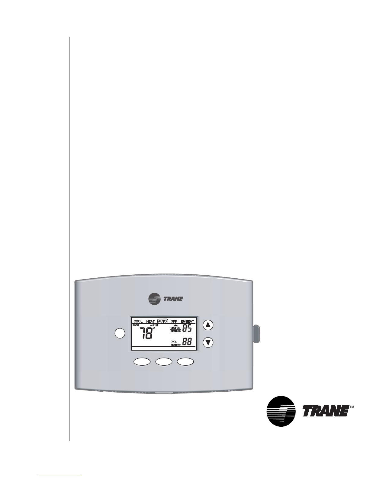
Trane TCONT401AN21MA Comfort Control Manuale utente

Fan Mode
Filter/OD
$
XR401
Comfort
Control
TCONT401AN21MA
Comfort Control
Owner’s Manual
Pub. No. 22-5206-01
Trane
6200Troup Highway
Tyler,Texas 75711
For more information contact
your local dealer (distributor)

Table Of
Contents
Page - 2
Pub. No. 22-5206-01
Fan Mode
Filter/OD
$
Energy Savings
Page 10.
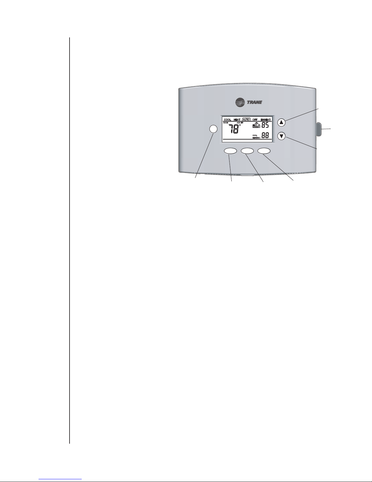
Up Arrow - Increase
temperature Page 5.
Down Arrow - Decrease
temperature Page 5.
Filter Reminder /
Outdoor Temperature
Page 7.
Fan ON / AUTO
Page 6.
Mode: Cool, Heat,
Auto, Off, EMHeat
Page 4.
Comfort
Information
Drawer Page 16.
Page
3 Introduction
4-11 Keypad functions
12-16 Features
17 Factory settings
18-19 Comfort Control Setup
20-21 Troubleshooting
22-23 Warranty
Page - 23
Some states do not allow limitations on how long an implied warranty last or do not
allow the exclusion or limitation of incidental or consequential damages, so the above
limitation may not apply to you. This warranty gives you specific legal rights, and you
may also have other rights which vary from state to state.
Parts will be provided by our factory organization or an authorized service organization in
your area. All you need to do is look us up in the Yellow Pages or write to the address
given below. If you wish further help or information concerning this warranty, contact:
Trane
Troup Highway
Tyler, Texas 75711-9010
Attention: Manager, After Sale Support
Pub. No. 22-5206-01

Introduction
Page - 3
Congratulations on the purchase of your new Trane XR401 Comfort Control! Your
XR401 Comfort Control combines the latest digital control technology with intuitive
functions that make this control simple to understand and easy to operate. You’ll enjoy
lower utility bills at the touch of a button with the energy efficiency features built into
your XR401 Comfort Control. Your comfort settings are automatically stored in the
XR401 Comfort Control’s memory eliminating the need for battery backup in the event of
power loss. Simply follow the steps in this instruction manual and begin enjoying the
benefits of your new Trane XR401 Comfort Control.
Pub. No. 22-5206-01
Warranty
Limited Warranty
Low Voltage Comfort Control
This warranty is extended by Trane to the original purchaser and to any succeeding owner
of the real property to which the Comfort Control is originally affixed, and applies to
products purchased and retained for use within the U.S.A. and Canada.
If any part of your Comfort Control fails because of a manufacturing defect within 5
years from the date of the original purchase, Warrantor will furnish, without charge, a
new Comfort Control. Any local transportation, related service labor and diagnosis
calls are not included.
This Warranty does not cover failure of your Comfort Control if it is damaged while in
your possession or if the failure is caused by unreasonable use. In no event shall Warran-
tor be liable for incedental or consequential damages. In no event shall any implied
warranty of merchandise or fitness for use exceed the terms of the limited warranty
stated above.
Page - 22
Pub. No. 22-5206-01

Page - 4
Pub. No. 22-5206-01
Keypad
Functions
Mode
Mode
MODE
Page - 21
Pub. No. 22-5206-01
Table 2
Troubleshooting
(Continued)
Symptom Possible Cause Action
Heating will not come
on.
1. System Mode not set to Heat.
2. Minimum off time delay being enforced. "waiting displayed".
3. Loose connection to control or system.
4. Heating system requires service or
control requires replacement.
1. Set Mode to heat and raise the setpoint above room temperature.
2. If heating does not come on within 5 minutes, Check Heating.
3. Check - Repair connections.
4. Repair system / Replace control.
Cooling will not come
on.
1. System Mode not set to Cool.
2. Minimum off time delay being enforced "waiting displayed".
3. Loose connection to control or system.
4. Cooling system requires service or
control requires replacement.
1. Set Mode to cool and lower the setpoint below room temperature.
2. If cooling does not come on within 15 minutes, contact servicer.
3. Repair connections.
4. Repair system / Replace control.
Cool ON or Heat ON
is displayed, but no
warm or cool air is
coming from the
registers.
1. The heating equipment turns on the
fan when the furnace has warmed up to a
setpoint.
2. Heating or cooling equipment is not
operating.
1. Wait one minute after seeing the ON icon and then check the registers.
2. Check Heating and Cooling system.
Control does not
respond to keypad
presses.
1. "Keypad locked" icon is displayed on LCD.
2. Keypad failure.
1. Unlock keypad - press Up+Down arrow together until "Keypad Locked"
disappears.
2. Replace Control.
Fan does not operate
properly in heat or
cool mode.
1. Incorrect wiring.
2. Heating or cooling equipment inoperative.
1. Correct wiring.
2. Repair system.
Fan runs all the time. 1. Fan mode set to ON.
2. Shorted control wiring.
1. Set fan mode to AUTO.
2. Check / Repair wiring.
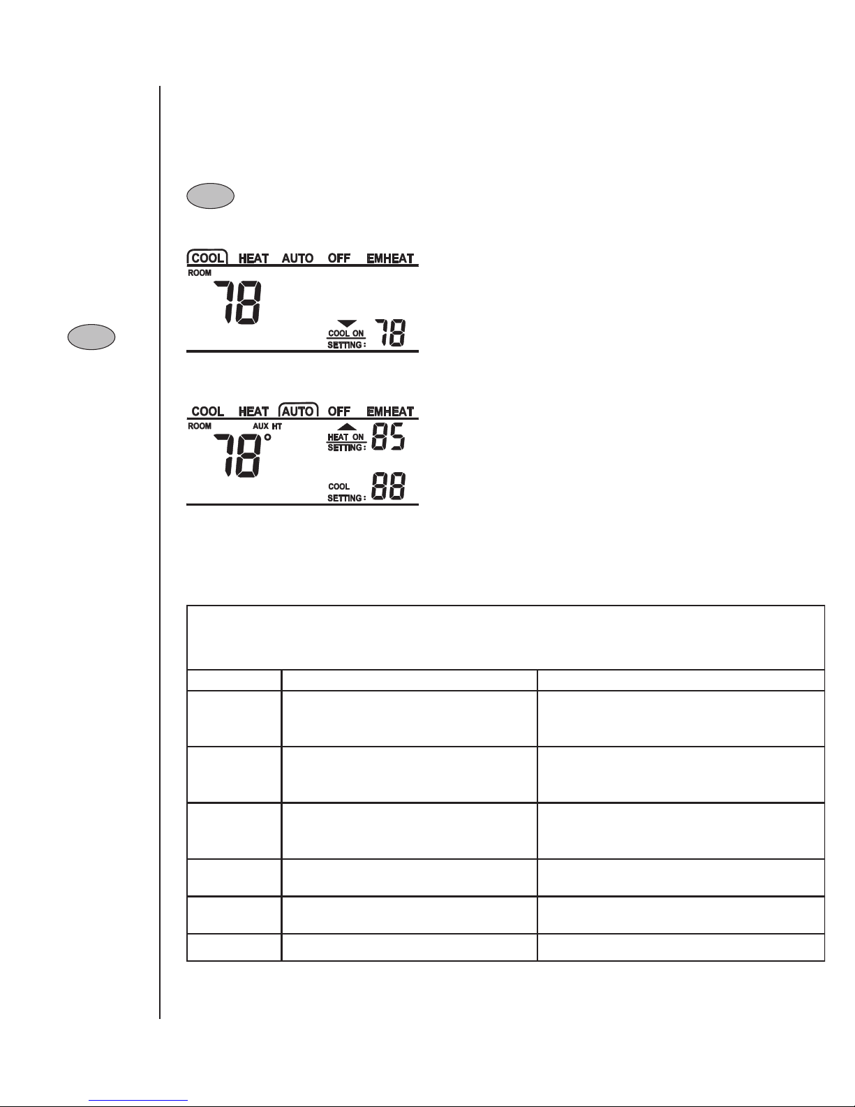
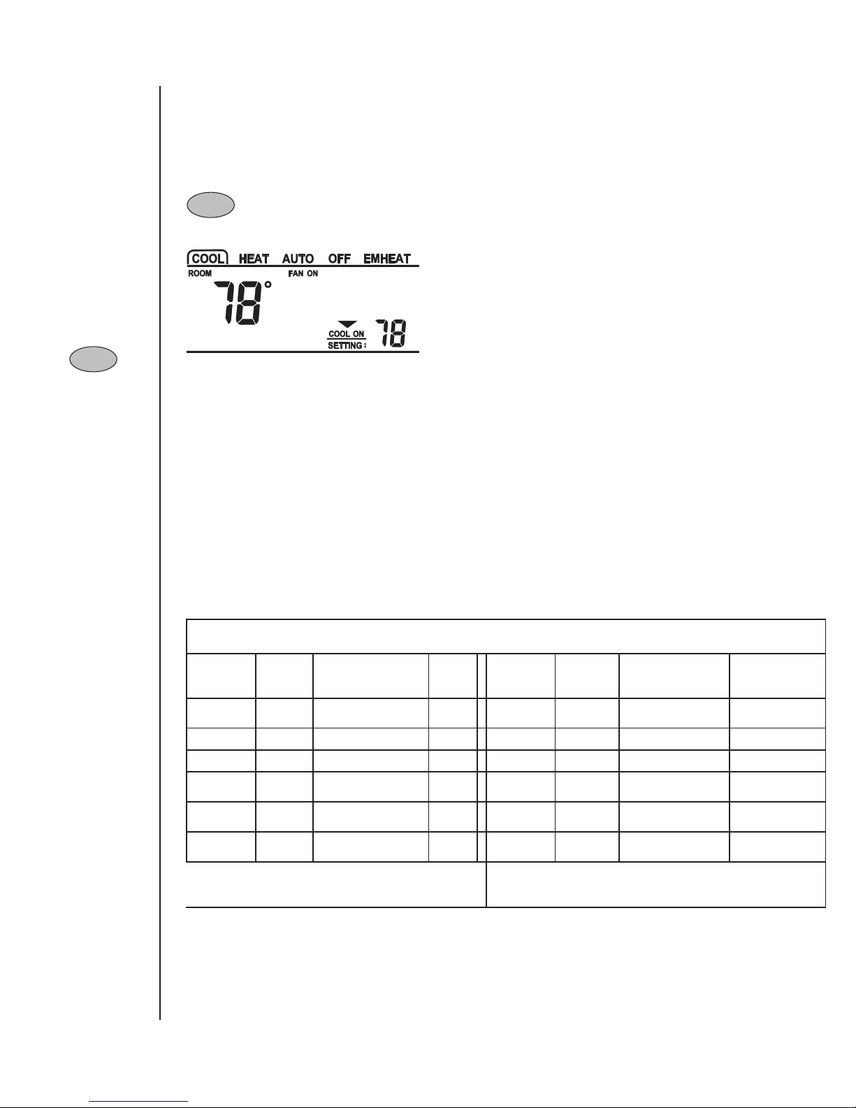
- Pressing this key changes the system mode to Heat, Emergency Heat, Cool,
Automatic or Off. NOTE: Emergency Heat available only on Heat Pump
applications.
A border will appear around the mode on the display
to show the system mode you’ve selected.

Page - 5
Pub. No. 22-5206-01
UP / DOWN Arrow
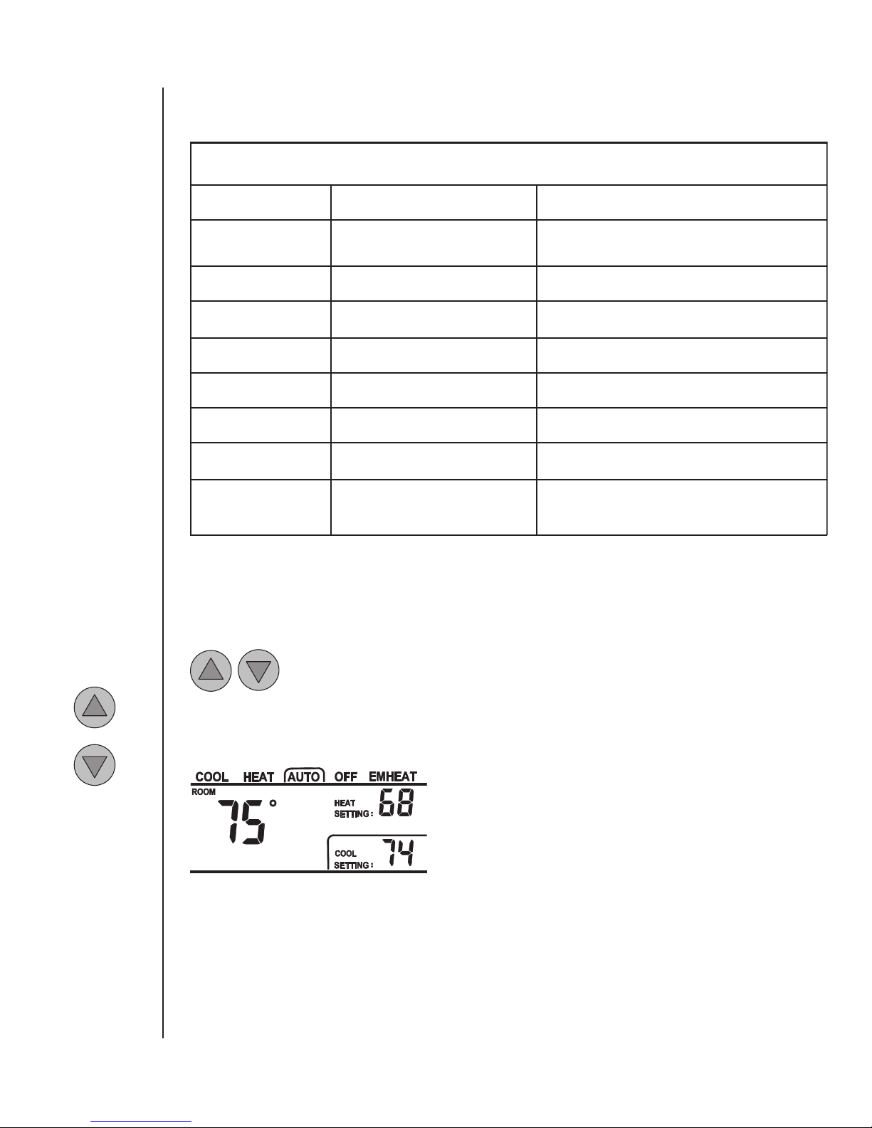
- Use these keys to raise or lower the Heat or Cool Setting.
- The first key press turns on the back lighting and a border around the setting to be
adjusted without changing the setting.
- Pressing the Up or Down arrow again will raise or
lower the setting that has the border around it.
- If you press and hold the Up or Down arrow, the temperature setting will advance
rapidly.
- When the control is set to Auto mode, pressing the Mode key once changes the position
of the border to heat or cool.
Trouble
-shooting
Page - 20
Pub. No. 22-5206-01
Table 2
Troubleshooting
Symptom Possible Cause Action
Display will not come on.
1. Blown fuse or tripped circuit breaker.
2. Furnace power switch OFF.
3. Furnace blower compartment door or panel
loose or not properly installed.
1. Replace fuse or reset breaker.
2. Turn switch to ON.
3. Replace door panel in proper position to engage safety interlock or
door switch.
Temperature display is incorrect. Temperature display needs calibration. Calibrate Sensor - User Setup Step 49.
Outdoor temperature display is
incorrect.
Temperature display needs calibration.
Outdoor sensor located in poor sensing location.
1. Calibrate Sensor - User Setup Step 50.
2. Disconnect sensor and check circuit resistance value - Table 4.
3. Relocate outdoor sensor.
Cannot set Heating setpoint
above 80 degrees Deadband between Heating and Cooling set to high Decrease Deadband setting - User Setup Step 42.
"Service" Flashing on and off. Control EEPROM write error. Press any key and Check / Re-enter Setup Choices.
"Service" solid on and "--" in
temperature display. Indoor temperature sensor open or shorted Replace Control
Outdoor temperature display
shows "--" and Service indicator
on solid.
Outdoor temperature sensor open or shorted 1. Check outdoor sensor wiring.
2. Replace outdoor sensor.
Temperature setting will not
change. (Example: Cannot set
heating higher or cooling lower).
1. Upper and/or lower temperature limits were
reached.
2. "Keypad locked" is displayed on LCD.
1. Check the temperature setpoints:
Heating limits are 40 - 85F.
Cooling limits are 65 - 90F.
2. Unlock keypad - press Up+Down arrow together until icon disappears.

Page - 6
Pub. No. 22-5206-01
FAN
- Pressing this key selects whether the indoor fan motor runs in automatic or
continuous mode.
The FAN ON indicates that you have selected to
operate the fan in continuous mode.
Pressing the Fan keypad button again returns the
indoor fan mode of operation to automatic and FAN
ON goes away.
Fan
Fan
Keypad
Functions
(cont-)
Page - 19
Pub. No. 22-5206-01
Lock - Unlock Keypad:
Press and hold Up Arrow and Down Arrow at the same time for several seconds.
(“Keypad Locked” icon will display on LCD screen)
User
Setup
Options
(cont-)
Table 1
Comfort Control Setup
Menu Item Factory
Setting
Setting (Choices)
(Press UP or DOWN arrow)
Step
(Press
Mode or
Fan)
Menu Item Factory
Setting
Setting (Choices)
(Press UP or DOWN arrow)
Step
(Press Mode or Fan)
Temperature
Display 00 = Fahrenheit
1 = Celcius 40
Energy Savings -
Heating Setpoint
Offset
51 - 45 Degrees Fahrenheit
1 - 25 Degrees Celcius 46
Auto or Manual
Changeover 10 = Manual
1 = Auto 41 Indoor Filter Timer
Method 00 = Calendar Days
1 = Fan Run Time Days 47
Setpoint Deadband 3 2 - 10 Degrees 42 Indoor Filter
Reminder - Days 30 1 - 180 Days
0 = Disable 48
Waiting Icon 1 0 = Disable
1 = Enable 43 Calibrate Indoor
Temperature 0
Calibrated Room Temperature
+ / - 5 Degrees (1/2 degree
increments)
49
Cooling Droop 1
0 = Off
1 = 1 Degree
2 = 2 Degrees
44 Calibrate Outdoor
Temperature 0
Calibrated Outdoor Temperature
+ / - 5 Degrees (1/2 degree
increments)
50
Energy Savings -
Cooling Setpoint
Offset
51 - 25 Degrees Fahrenheit
1 - 15 Degrees Celcius 45 Exit Setup
(Press Mode) SA
SA = Save
US = Default User Settings
CA = Cancel
99
(Exit)
Note: Pressing the Energy Savings Key ($) anytime during setup will advance to step 99.
Step 99 - Make setting selection and then press MODE to exit.
SAve = Save selections
USer = Default user settings
CAncel = Cancel Selections for current session and return to previous session selections.

FILTER/OD
Filter/OD
Page - 7
Pub. No. 22-5206-01
Filter/OD
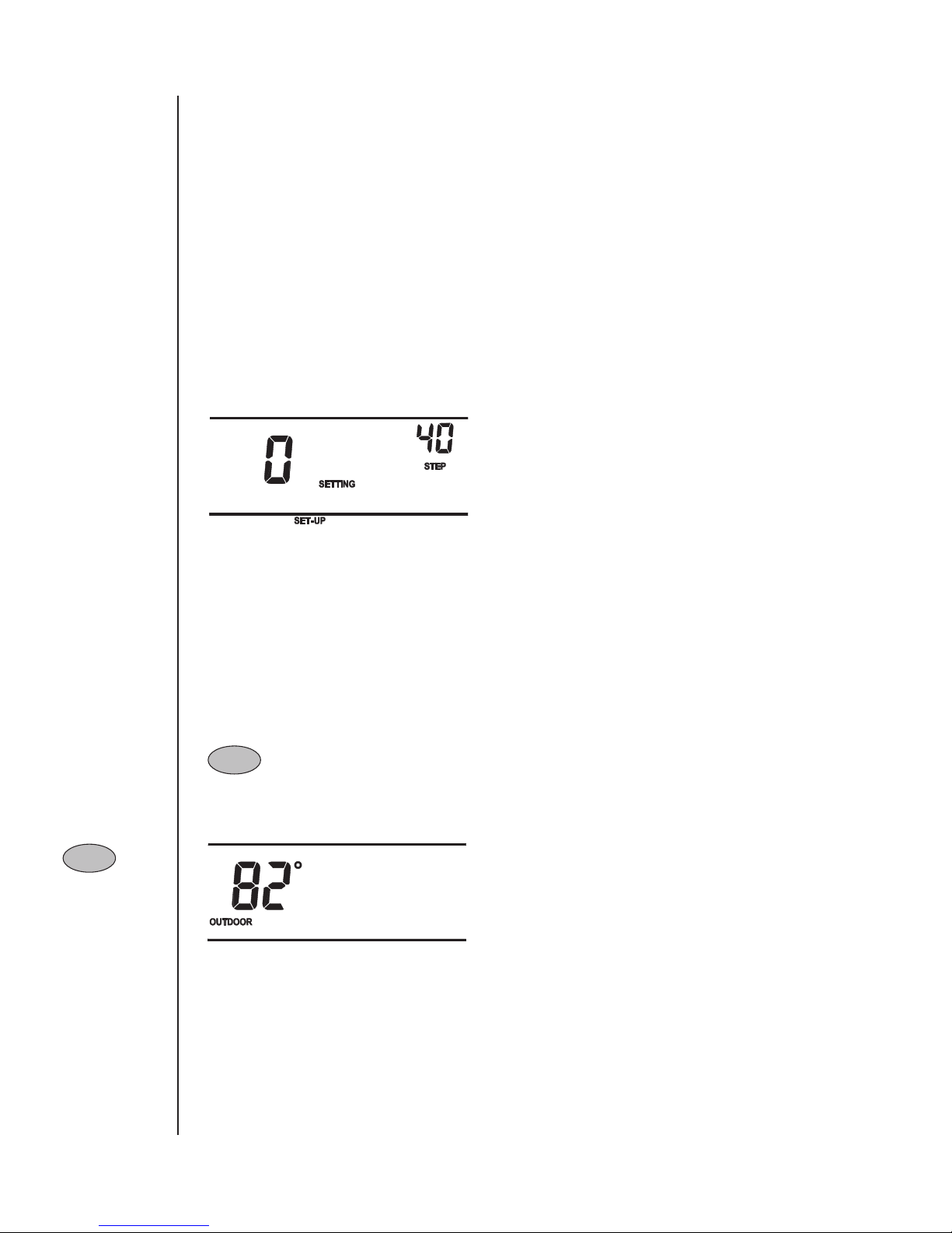
- When the optional outdoor sensor is installed, outdoor temperature can be
viewed on the Comfort Control’s display by simply pressing the “FILTER/OD”
key.
Page - 18
Pub. No. 22-5206-01
Entering User Setup:
Press and hold the MODE and FAN keypad buttons at the same time.
Keypad Navigation:
- Use the MODE or FAN buttons to navigate forward and backward through the Setup steps.
- Press MODE to advance forward to the next step.
- Press FAN to return to the previous step.
- Use the UP and DOWN arrow keypad buttons to select or change Setup options.
User
Setup
Options

Page - 8
Pub. No. 22-5206-01
Filter/OD
Filter/OD
FILTER/OD
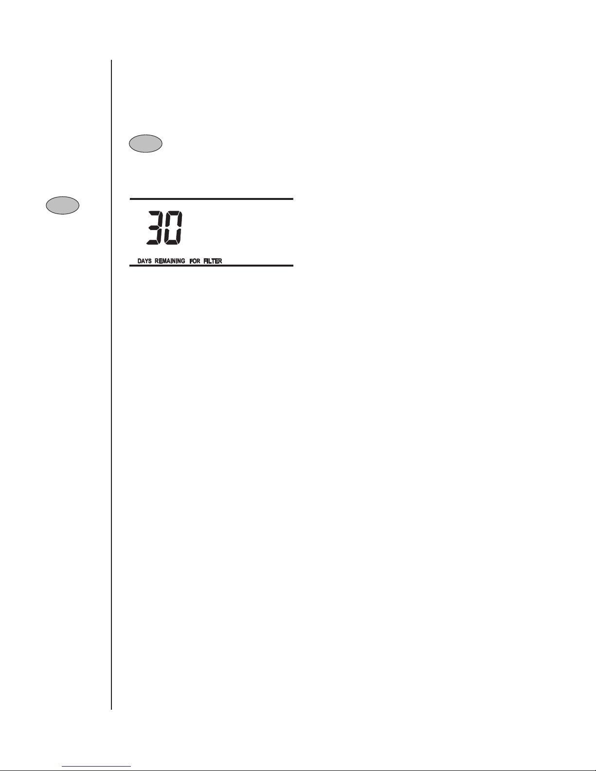
- Press this key twice to display how many days remain before time to replace or
clean the filter. The “FILTER/OD” indicator will flash on the display when the
filter timers days remaining reaches zero.
- Press the “FILTER/OD” key twice after cleaning or
replacing the filter to turn off the filter indicator and
reset the timer.
- If the filter is serviced before the timer expires, press the “FILTER/OD” key twice to
display the “days remaining for filter”. Press the Down arrow to change the remaining
days to zero. Press the “FILTER/OD” key twice to reset the timer.
Keypad
Functions
(cont-)
Page - 17
Pub. No. 22-5206-01
Factory
Default
Settings
User Defined Options and Factory Default Settings: (See Table 1, page 19)
Temperature Display - Fahrenheit or Celsius (Default is Fahrenheit)
Auto or Manual Changeover - (Default is Auto)
Setpoint Deadband - 2 - 10 degrees (Default is 3 degrees)
Waiting Indicator - Enable or Disable (Default is Enable)
Cooling Droop - Off, 1, or 2 degrees (Default is 1 degree)
Energy Saving Cooling Setpoint Offset - 0 - 25 degrees (Default is 5 degrees)
Energy Saving Heating Setpoint Offset - 0 - 45 degrees (Default is 5 degrees)
Indoor Filter Timer Method - Calendar Days or Fan Run Time Days - (Default is Calendar Days)
Indoor Filter Timer Days - 1 - 180 days (Default is 30 days)
Calibrate Indoor Temperature - + / - 5 Degrees (Default is 0 degrees)
Calibrate Outdoor Temperature - + / - 5 Degrees (Default is 0 degrees)

Page - 9
Pub. No. 22-5206-01
Filter/OD
Filter/OD
FILTER/OD
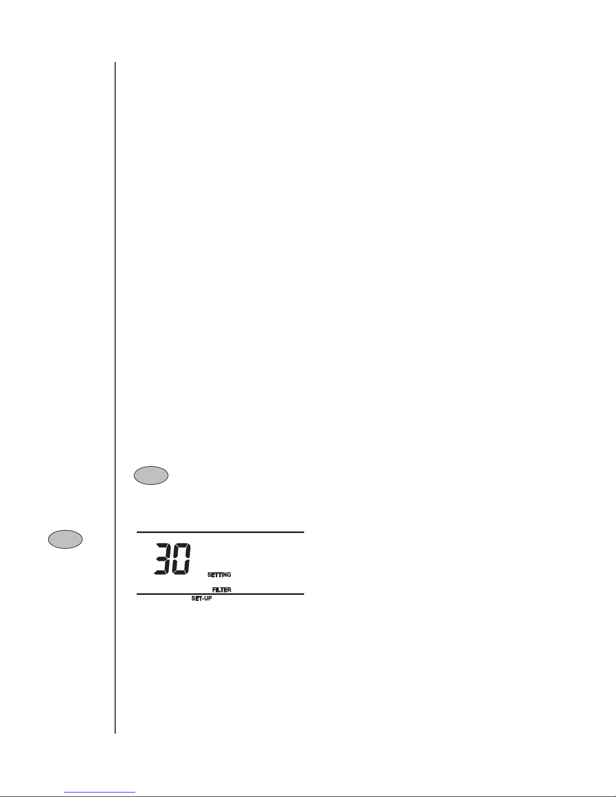
- If you press and hold the filter/OD keypad button for several seconds, the display
changes to the Quick Setup option for the filter timer. Use the UP or DOWN
arrow keypad buttons to change the timer setting if desired, 1 - 180 days.
NOTE: Setting to 0 will disable filter timer.
- Press the filter/OD button again to return to normal
display or just wait a few seconds and the display will
return on its own.
Page - 16
Pub. No. 22-5206-01
Calibrate Outdoor Temperature
This option allows calibration (or deliberate miscalibration) of the outdoor temperature
sensor. The selected number is number of degrees, plus or minus, which will be added to
actual temperature. The number can range between + 5 and - 5 degrees in 1/2 degree incre-
ments. Factory default is 0. This adjusted value will be used and displayed as actual tempera-
ture. For example, if 2 is selected, 72 degrees actual will read 74 degrees.
Comfort Information Drawer
The drawer attached to the mounting base of the control is designed to provide a convenient
location for the user to locate their local servicer. A standard business card can be folded and
inserted into the slot on the drawer to remind the User whom to call when service is re-
quired.
Features
(cont-)

Page - 10
$
Pub. No. 22-5206-01
$
Energy Savings
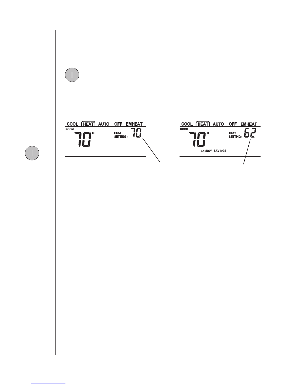
- Use this key to lower your systems energy consumption and save money at the
same time! Pressing the Energy Savings keypad button changes the indoor tempera-
ture setting to a warmer temperature when the system is operating in the cooling
mode and to a cooler indoor temperature setting when operating in the heating
mode. Energy Savings will appear on the display.
$
Example: Heating offset of 8 degrees.
Keypad
Functions
(cont-)
Page - 15
Pub. No. 22-5206-01
Service Indicator
“SERVICE” automatically flashes when an internal fault or error has been detected by the
control. See Table 2 on pages 20 & 21.
Wait Indicator
“WAITING” will illuminate when the indoor setpoint is moved in the direction of calling
for additional system capacity. “WAITING” indicates that the control is adjusting to the new
settings.
Calibrate Indoor Temperature
This option allows calibration (or deliberate miscalibration) of the room temperature sensor.
The selection is the number of degrees added to actual temperature. The number can range
between + 5 and - 5. Factory default is 0. This adjusted value will be used as actual tempera-
ture for both display and control action. For example, if 2 is selected, 72 degrees actual will
read 74 degrees.
Questo manuale è adatto per i seguenti modelli
1
Indice
Altri manuali Trane Regolatori di temperatura

Trane
Trane ComfortLink II XL 850 Manuale utente

Trane
Trane ZUSTATALS510 Manuale utente

Trane
Trane WFS 1 Guida rapida

Trane
Trane ZUSTATALP510 Istruzioni per il montaggio

Trane
Trane VariTrac Manuale utente

Trane
Trane PolyTherm ARTC-SVX005A-EN Istruzioni per l'installazione e il funzionamento

Trane
Trane ZSENS930AW00MA Istruzioni per il montaggio

Trane
Trane TCONT800AS11AA Manuale utente

Trane
Trane X1379088401 Istruzioni per l'installazione e il funzionamento

Trane
Trane TZEMT524AA21MA Istruzioni per il montaggio