Triton 9100 Manuale utente

iLAN Ethernet Box for 9100
Installation Manual
07103-00154 March 11, 2014
Corporate Headquarters:
21405 B Street
Long Beach, MS 39560
Phone: (800) 259-6672
Fax: (228) 868-9445
Copyright Notice
© 2014 Triton. All Rights Reserved. TRITON logo is a
registered trademark of Triton Systems of Delaware LLC.
DOCUMENT UPDATES
March 11, 2013 Original
March 19, 2014 Added Software Dependency
Software Dependency
A software update is required. The most current software and Release Notes are available for your unit
on the Triton web site (www.TritonATM.com) or contact Triton Technical Support. The software must
be US 7.3 or later version.
External Ethernet Option Upgrade Kit for 9100
Tools Required
-Small flathead screwdriver
-#2 Phillips screwdriver
-11/32 open end wrench
-Side cutters
KIT P/N:
06200-00192 iLAN Kit with Cables
PARTS SUPPLIED
Description Quantity
Secure iLAN Device Server 1
Ethernet Cable 166” 1
iLAN Communication Cable 1
iLAN Power / Main Board Splitter Cable 1
Velcro Loop-side Round Dot 2
Velcro Hook-side Round Dot 2
6” Ty Wraps 4

Tools Required
-Small flathead screwdriver
-#2 Phillips screwdriver
-11/32 open end wrench
-Side cutters
KIT P/N:
06200-00135 External Ethernet Options Upgrade Kit for 9100
PARTS SUPPLIED
Description Quantity
Secure iLAN Device Server 1
Ethernet Cable 166” 1
iLAN Communication Cable 1
iLAN Power / Main Board Splitter Cable 1
Main Board Housing w/ Ethernet Option 1
External Ethernet Option Bracket 1
#8-32 Hex Nut 2
#8-32 – 1” Phillips Flathead Screw 1
#8-32 3/4” Phillips Pan Head Screw 1
Modem to Ethernet Adapter Board 1
4.5” Red TY Wrap 2
Velcro Loop-side Round Dot 2
Velcro Hook-side Round Dot 2
6” TY Wrap 4
iLAN Ethernet Box Upgrade Prep ………………………… Page 1
External Ethernet Removal ………………………………... Page 6
iLAN Ethernet Box Installation …………………………… Page 9
Management Functions ………..…………………………… Page 20
Page1of30
iLANEthernetBoxUpgradePrep
NOTE:ToassistinreconfiguringtheATM,performa“TestReceipt
Printer”toprintconfigurationbeforeshuttingtheunitdown.
Step1:Unlockandopenthecontrolpanel.TurnthepowersupplyswitchtotheOFF(0)position.
Step2:Usingthesidecutters,cuttheTYWrapssecuringtheprinterpowercabletothesideofthemain
boardcover.IfyourunithascableclipsonthemainboardcoverinplaceoftheTYWraps,removethe
tubingfromtheclipsthenremovethecablesfromthetubingandsetthetubingasideforreinstallation.
Step3:Disconnectallthecablesfromeachsideofthemainboardassembly.Removethemainboard
assemblyfromtheunitbyremovingthethreescrewssecuringtheassembly.
Page2of30
Step4:Removethe2screwsfromthetopandbottomoftheassembly.Setthescrewsasidefor
reinstallation.
Step5:Gentlyseparatethetopandbottomofthemainboardcover.Setthetopaside.
Step6:Usingsidecutters,cuttheTYWrapthatsecuresthemodemmodule.DiscardtheTYWrap.
Removethemodemmodulebygentlyliftingitstraightupunseatingitfromsocket.
Page3of30
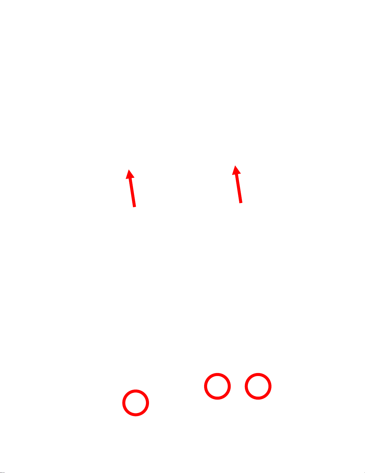
Step7:Thetwoscrewssecuringthemainboardneedtobereplaced.RemovethescrewholdingtheTY
Wrapclipandreplaceitwiththe#8‐32–1”FlatHeadedPhillipsscrew.EnsuretheTYWrapclipremains
ontheboard.Removethesecondscrewandreplaceitwiththe#8‐32–3/4”PanHeadedPhillipsscrew.
Thescrewswillprotrudeonthebacksideofthecover.
PanHeaded
PhillipsScrew
FlatHeaded
PhillipsScrew

Page4of30
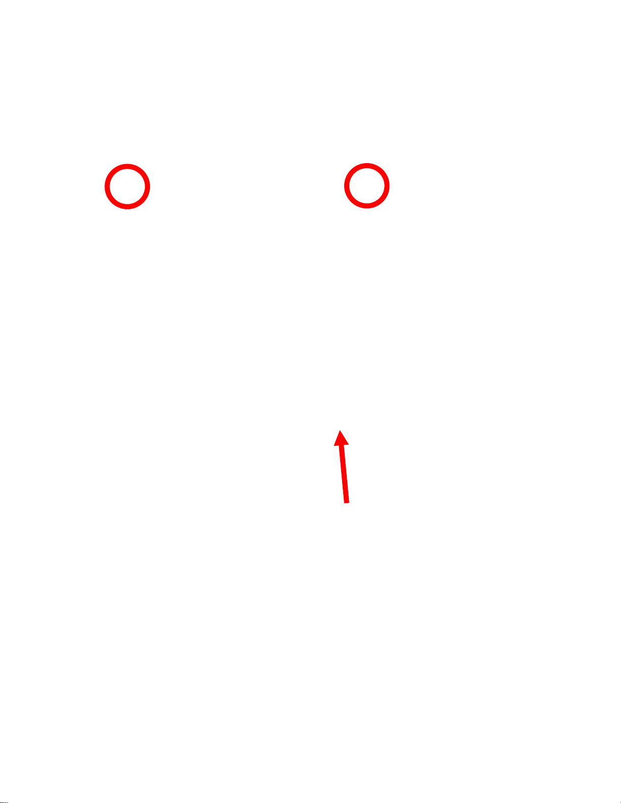
Step8:InserttheredTYWrapintotheTYWrapclip.InstalltheExternalEthernetAdapterinthesocket
previouslyusedforthemodemmodule.Ensuretheadapterisseatedcorrectlyonthesocket.Secure
theTYWraparoundtheadapterandcutoffexcess.
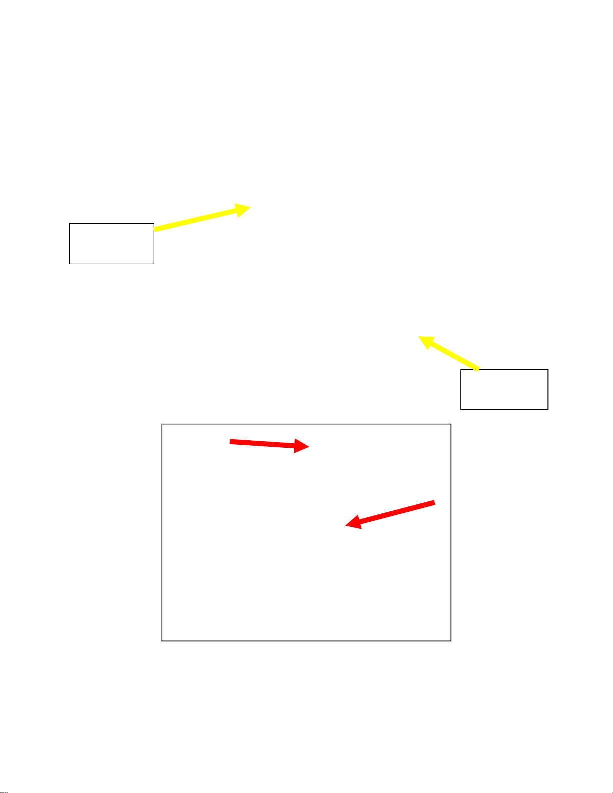
Step9:Reinstallthetopmainboardcover.IftheoriginalmainboardtopcoverdidNOThavethesquare
cut‐outfortheEthernetoption,replaceitwiththetopmainboardhousingsuppliedinthekit.(Besure
toremovethe“L”bracketfromtheoriginaltopcoverandinstallitontothenewtophousing.)
SecuretheassemblytogetherwiththetwoscrewsremovedinStep4.

Page5of30
Step10:ReinstallthemainboardassemblyintotheunitwiththethreescrewsremovedinStep3.
Step11:Plugallthecablesbackintothecorrectportsonthemainboardexceptthephonecable.Leave
thephonecableunplugged.Routethephonecablebackonitselfthroughthecablecliptosecureitout
oftheway.

Page6of30
ExternalEthernetRemovalInstructions
Step1:Unlockandopenthecontrolpanel.TurnthepowersupplyswitchtotheOFF(0)position.
Step2:Unplugtheserialcablefromthesideofthemainboardassembly
Step3:RemovethetwohexnutssecuringtheEthernetboxandbrackettothesideofthemainboard
assembly.Setthetwohexnutsasideforreinstallation.

Page7of30
Step4:UnplugtheEthernetcablefromtheEthernetbox.
Step5:SeparatetheEthernetboxandbracket.DiscardtheEthernetboxandserialcable.
Altri manuali per 9100
1
Indice


