Trox Technik X-AIRCONTROL Manuale utente
Product overview
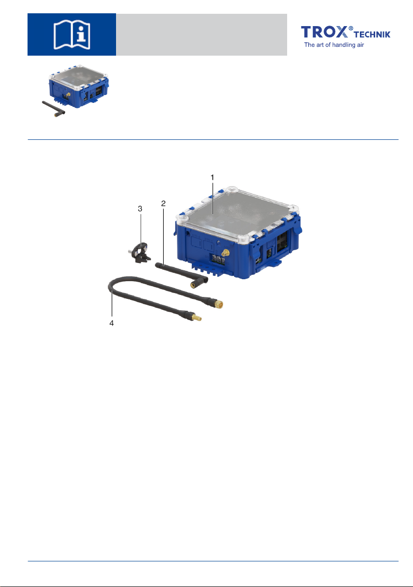
Fig. 1: FAM-RD
1 FAM-RD (Field Application Module with Radio-
Duct expansion module)
2 Antenna
3 Antenna mounting bracket
4 Antenna cable, 50 cm long
Installation manual GB/en
X-AIRCONTROL
FAM-RD
TROX GmbH
Heinrich-Trox-Platz
47504 Neukirchen-Vluyn
Germany
Phone: +49 (0) 2845 2020
+49 (0) 2845 202-265
E-mail: [email protected]
http://www.troxtechnik.com
A00000092825, 09/2022,
X-AIRCONTROL FAM-RD 1

Connections and interfaces
Fig. 2: Connections
Item Description Note
1 Sensor connections S1, S2, S3 Not used
2 Antenna connection
3 CL1
CL2
Not used
4 T5 = X-AIRCONTROL connection
5 Push button for enabling service port T1
6 T1 = service and multi port
T2 -T4 = multi ports
T2-T4 not used
7 Digital input 1 (DI1 + GND)
Digital input 2 (DI2 + GND)
Digital input 3 (DI3 + GND)
Analogue input 1 (AI1 + GND)
Temperature input (TI1 + GND)
Not used
8 Power = power supply
9 Digital output DO (NO, C, NC) Not used
Product overview
X-AIRCONTROL FAM-RD2

General information
About this manual
This operating and installation manual enables
operating or service personnel to correctly install
the TROX product described below and to use it
safely and efficiently.
This operating and installation manual is intended
for use by fitting and installation companies, in-
house technicians, technical staff, instructed per-
sons, and qualified electricians or air conditioning
technicians.
It is essential that these individuals read and fully
understand this manual before starting any work.
The basic prerequisite for safe working is to comply
with the safety notes and all instructions in this
manual.
The local regulations for health and safety at work
and general safety regulations also apply.
This manual must be given to the system owner
when handing over the system. The system owner
must include the manual with the system documen-
tation. The manual must be kept in a place that is
accessible at all times.
Illustrations in this manual are mainly for informa-
tion and may differ from the actual design.
Other applicable documentation
In addition to these instructions, the following docu-
ments apply:
FAM-RD product information
X-AIRCONTROL commissioning and service
manual
Project-specific wiring documents
Complete documentation
Installation and operating manual
This document is the installation manual for the
product.
For more information on commissioning and
operation please refer to the installation and
operating manual. You can download the manual
from our website www.troxtechnik.com.
TROX Technical Service
To ensure that your request is processed as quickly
as possible, please keep the following information
ready:
Product name
TROX order number
Delivery date
Brief description of the fault
Online www.troxtechnik.com
Phone +49 2845 202-400
Limitation of liability
The information in this manual has been compiled
with reference to the applicable standards and
guidelines, the state of the art, and our expertise
and experience of many years.
The actual scope of delivery may differ from the
information in this manual for bespoke construc-
tions, additional order options or as a result of
recent technical changes.
The obligations agreed in the order, the general
terms and conditions, the manufacturer's terms of
delivery, and the legal regulations in effect at the
time the contract is signed shall apply.
Warranty claims
The provisions of the respective general delivery
terms apply to warranty claims. For purchase
orders placed with TROX GmbH, these are the reg-
ulations in section "Vl. Warranty claims" of the
Delivery Terms of TROX GmbH, see
www.trox.de/en/.
General information
X-AIRCONTROL FAM-RD 3

Copyright
This document, including all illustrations, is pro-
tected by copyright and pertains only to the corre-
sponding product.
Any use without our consent may be an infringe-
ment of copyright, and the violator will be held liable
for any damage.
This applies in particular to:
Publishing content
Copying content
Translating content
Microcopying content
Saving content to electronic systems and
editing it
Safety notes
Symbols are used in this manual to alert readers to
areas of potential hazard. Signal words express the
degree of the hazard.
Comply with all safety instructions and proceed
carefully to avoid accidents, injuries and damage to
property.
DANGER!
Imminently hazardous situation which, if not
avoided, will result in death or serious injury.
WARNING!
Potentially hazardous situation which, if not
avoided, may result in death or serious injury.
CAUTION!
Potentially hazardous situation which, if not
avoided, may result in minor or moderate injury.
NOTICE!
Potentially hazardous situation which, if not
avoided, may result in property damage.
ENVIRONMENT!
Environmental pollution hazard.
Safety
Correct use
FAM-RD is used as part of X-AIRCONTROL for
radio-based data transmission through ducting.
The data is transmitted in two directions between
zone module and zone master.
Safety
X-AIRCONTROL FAM-RD4

Correct use requires that both the transmitter
module and the receiver module are placed in the
same duct system, i.e. either in the supply air duct
or in the extract air duct. FAM-RD must not be used
outdoors.
Residual risks
A power failure will interrupt data transmission. If a
system has to be highly reliable and available, you
should take backup measures to prevent problems
in case of a power failure.
Also, the radio communication between the various
nodes of an X-AIRCONTROL system can be inter-
rupted by interference. This, too, may lead to trans-
mission losses.
If a system has to be highly reliable and available, a
wired connection is the better option for data trans-
mission.
Incorrect use
Do not use the product for areas of application that
are not described in this manual.
Do not use the product:
outdoors
in wet areas
in areas with potentially explosive atmospheres
Dangers and risks
NOTICE!
Risk of damage to property due to large tem-
perature differences
If any electronic components have been kept in
an unheated area, condensation may form and
damage the electronic components beyond
repair.
– Before you start commissioning, make sure
that all devices have warmed up to the
ambient temperature. Only after about
2 hours will the system have reached
ambient temperature.
NOTICE!
Risk of damage to property due to foreign
matter and liquids!
Foreign matter and liquids that get into the unit
may damage the electronic parts.
– Remove foreign matter, if any.
– If the device emits a smell or smoke, have it
checked by the manufacturer.
– If liquid gets into the module, let the module
completely dry before commissioning.
NOTICE!
Risk of damage to property!
Over tightening the fixing screws may damage
the device.
– Tighten the screws only finger-tight.
Qualified staff
The work described in this manual has to be carried
out by individuals with the qualification, training,
knowledge and experience described below:
Skilled qualified electrician
Skilled qualified electricians are individuals who
have sufficient professional or technical training,
knowledge and actual experience to enable them to
work on electrical systems, understand any poten-
tial hazards related to the work under consideration,
and recognise and avoid any risks involved.
Delivery and storage
Supply package
Check delivered items immediately after arrival for
transport damage and completeness.
Supply package
FAM-RD
Antenna
Antenna cable, 50 cm long
Antenna mounting bracket
Installation and operating manual
Delivery and storage
X-AIRCONTROL FAM-RD 5

Transport
If possible, take the product in its transport
packaging up to the installation location.
Do not remove the protective wrapping until
just before installation.
Storage
For temporary storage please note:
Leave the product in its packaging and do not
expose it to the effects of weather.
Store the product in a dry place and away from
direct sunlight.
Temperature –10 °C to +70 °C, humidity 90%
max. (no condensation)
Packaging
Properly dispose of packaging material.
Technical data
Dimensions
Fig. 3: Dimensions and fixing points
Technical data
Radio frequency 2.4 GHz
Max. radio transmission
output
100 mW
Power rating 5 VA
Encryption 128 bit AES
Power supply 24 V AC or DC
IEC protection class III (protective extra-low
voltage)
Ambient temperature 10 to 50 °C
Protection level IP20
CE conformity EMC directive
2014/30/EU
RoHS 2011/65/EU
Radio equipment
directive ‘RED
2014/53/EU’
Weight 500 g
Technical data
X-AIRCONTROL FAM-RD6

Installation
General installation information
Fig. 4: Positioning
Please note:
All modules that should communicate via radio
have to be installed in the same duct system,
i.e. either in the supply air duct or in the extract
air duct.
Place the antenna at least 1 m away from con-
trol dampers, shut-off dampers and measuring
devices.
The distance between the RadioDuct module
and the antenna must not exceed 40 cm.
The distance between the RadioDuct module
and ZMA / ZMO must not exceed 30 m.
Fix the antenna in the middle of the duct wall
(applies to rectangular ducts).
Fig. 5: Position on ducts
Fixing the antenna mounting bracket
Fig. 6: Fixing material (not included in the supply
package)
Fig. 7: Drill a hole
Æ
10 mm
Fig. 8: Use the screws to fix the bracket
Installation
X-AIRCONTROL FAM-RD 7
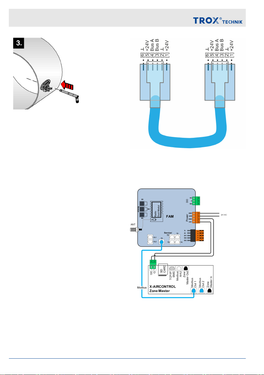
Fig. 9: Insert the antenna so that it locks into place
Electrical connection
General information
Connecting the power supply
Personnel:
Skilled qualified electrician
Supply voltage
Ä
‘Technical data’ on page 6
Do not connect more than 5 RadioDuct mod-
ules in series using the double terminals.
Note that a series connection with a zone
master or zone module requires 24 V AC
supply.
Modbus connection
Connect FAM-RD and zone master or zone module
with an RJ12 cable:
Type AWG26/6C
RJ12 plug (6P6C)
Max. length 30 m
Fig. 10: 1:1 Modbus connection
Wiring examples
Zone master
Fig. 11: Connection to zone master – data connec-
tion (Modbus) and external power supply
Electrical connection
X-AIRCONTROL FAM-RD8
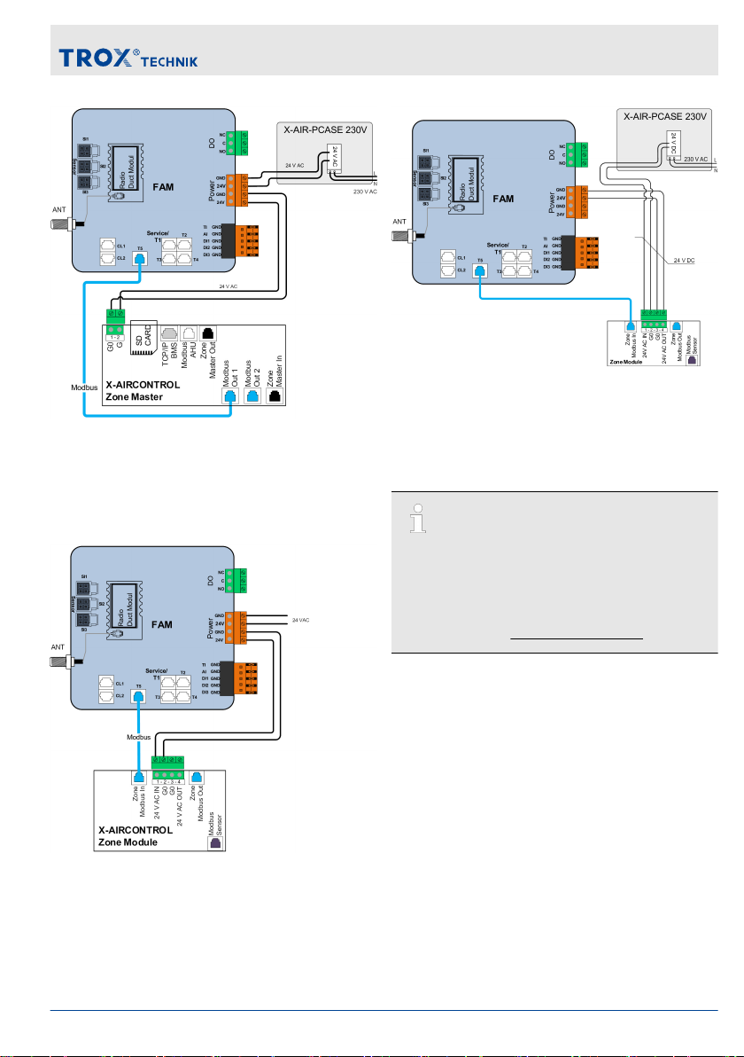
Fig. 12: Connection to zone master – data connec-
tion (Modbus) and power supply with X-AIR-
PCASE230 V
Zone module
Fig. 13: Connection to zone module – data connec-
tion (Modbus) and external power supply
Fig. 14: Connection to zone module – data connec-
tion (Modbus) and power supply with X-AIR-
PCASE230 V
Complete documentation
Installation and operating manual
This document is the installation manual for the
product.
For more information on commissioning and
operation please refer to the installation and
operating manual. You can download the manual
from our website www.troxtechnik.com.
Electrical connection
X-AIRCONTROL FAM-RD 9

X-AIRCONTROL FAM-RD10
Altri manuali per X-AIRCONTROL
1
Indice
Altri manuali Trox Technik Condizionatore d'aria


