Tuffcare R270 Manuale utente

© TUFFCARE, NC. ALL R GHTS RESERVED SMOOTH SEATED KNEE WALKER_V2.3
W W W. T U F F C A R E . C O M
ATTENTION
Before using this Mobility Device read this manual. f you are unable to
understand, contact your equipment provider for technical support before
attempting to use this product.
S
Sm
mo
oo
ot
th
h
S
Se
ea
at
te
ed
d
K
Kn
ne
ee
e
S
Sc
co
oo
ot
te
er
r
R
R2
27
70
0
O
Op
pe
er
ra
at
ti
in
ng
g
M
Ma
an
nu
ua
al
l

TABLE OF CONTENTS
TABLE OF CONTENTS
Table of Contents 1
Forward 2
Safety Precautions 3
Product Diagram 4
Specifications and Unpacking 5
ain Components 6
Assembly
Locking the Mainframe 7 - 8
Assembling the Steering Column 9
Locking the Steering Shaft 10 - 11
Attaching Handle Height Knob 12
Attaching the Seat Post 13
Attaching the Calf & Foot Pad 14
Attaching the Pouch 15
Adjustments
Adjusting the Seat Height 16
Adjusting the Seat Position 17
Adjusting the Handlebar Height 18
Adjusting the Calf Pad 19
Adjusting the Brake Tension 20
Operation 21 - 23
aintenance 24
Keep For Your Record 25
Limited Warranty 26
- 1 -
FORWARD
FORWARD
Congratulations on your purchase of a Tuffcare®
Smooth knee scooter! Our seated knee scooter is
designed especially for patients recovering from
knee surgery, ankle surgery, a broken knee, a broken
ankle, or a broken leg. While unable to walk, one
can gain mobility while seated and propel self
around a short distance without assistance. t’s also
great for building muscles during rehab recovery.
Our scooters are more comfortable and stable than
crutches and great for indoor and outdoor use.
- 2 -

- 3 -
SAFETY PRECAUTIONS
SAFETY PRECAUTIONS
L Do not operate your knee scooter until you have read and
fully understood this manual.
L Do not operate your knee scooter until its fully assembled
and checked.
L Do not leave your knee scooter unattended without locking
its brakes.
L Do not stop on a grade or ramp.
L Do not store this product at extreme temperatures (<0 >
40o).
L Do not exceed weight limit of 300 lbs or serious injury
could result
L maximum weight capacity for basket is 5 lbs.
L Watch out for: Uneven surfaces, cords, loose rugs, misc.
toys or tools on the ground, spilled water or oily surfaces.
L Do not perform adjustment to the knee scooter while it is
in use.
L Do not walk backwards before making sure no obstacles
are behind you.
L Do not make sharp turns.
L Do not turn or reverse on an incline.(maximum 10%
incline)
L All wheels must be in contact with the floor at all times
during use. This will ensure the knee scooter is properly bal-
anced.
L Do not lean over your knee scooter for any reason. Check
before use that the product is stable, rigid and that all rivets
and screws are fastened.
- 4 -
PRODUCT DIAGRAM
PRODUCT DIAGRAM
A. Brake Lock B. Brake Handle
C. Handgrip D. Steering Shaft
E. Pentagram Knob F. Seat Pad
G. Detachable Pouch H. Steering Column Lock
. Calf Pad J. 8” Rear Wheels
K. 10” Caster Wheels
S OOTH SEATED KNEE WALKER R270
A
B
C
D
E
H
I
K
F
G
K
- 5 -
Overall Height: 33 to 44 inches
Overall Length: 36 inches
Overall Width: 16.5 inches (Front), 10 inches (Rear)
Knee Pad Height: 23.5 to 31.5 inches
Folded Dimensions: 16.5 x 36 x 24 inches
Casters: 10 x 1.5 inches (Front), 8 x 1.25 inches (Rear)
Seat Size: 11 1/2 x 8 inches
Brake Handle: Dual brake with Parking Feature
Brake Type: Rear Drum Brake
aterial: Cold Roll Steel
Product Weight: 25 lbs
Weight Capacity: 300 lbs
UNPACKING
UNPACKING
⚠Dispose of the removed packaging at your local recycling
center. Discard the wrapper and box separately. Dispose of
the end-of-life item at a clean point.
⚠When cutting the zip ties, be cautious not do damage the
braking wires.
⚠nspect for any damage and check for hardwares listed on
page 4 and 5 according to the device model.
SPECIFICATIONS
SPECIFICATIONS
- 6 -
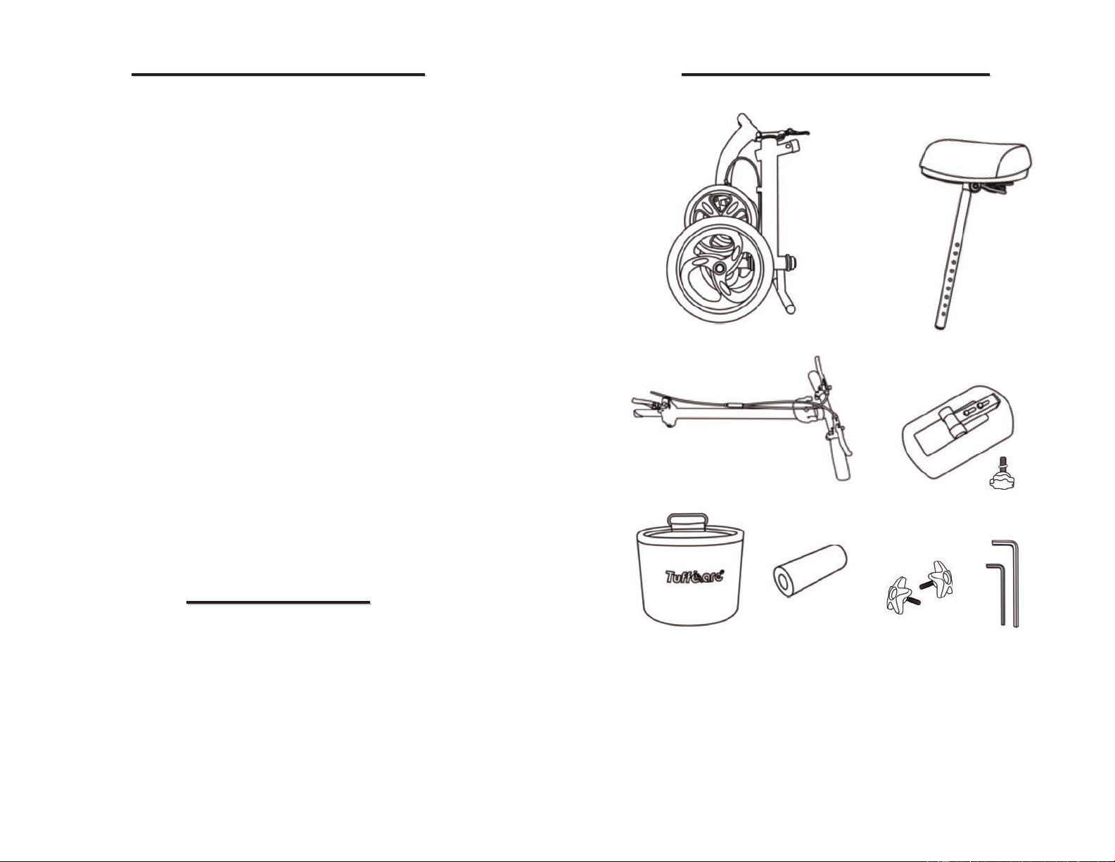
MAIN COMPONENTS
MAIN COMPONENTS
A. Main Frame B. Seat Pad
C. Steering Column D. Calf Pad & Heptagon Knob
E. Detachable Pouch F. Footrest Pad
G. 2 Pentagram Knobs H. Allen Wrench
A
B
C D
E
F G
H

- 7 -
1a. Remove all packing materials and set the knee scooter
standing along the rear wheels and the leg rest bar.
1b. Lift up the front frame in order to connect with the rear
frame. Be cautious not to place your hand or any object
between the two frame pieces.
1c. Fully extend the frame to straighten, pushing the end into
the column lock until the hinge pin clicks in place.
LOCKING THE AIN FRA E
ASSEMBLY
ASSEMBLY
- 8 -
1d. Ensure the frame is fully extended and the locking pin is
locked into place.
1e. Slide the frame lever onto the slot in the other direction to
the back side of the frame.
1f. Rotate the frame lever so it is pointing sideways.
1g. Press the lever firmly down until it is locked in place. No
rattling should occur at the locking mechanism at this time.
1d 1e
1f 1g
1h. To fold the frame, reverse the procedure in opposite order.
1i . Squeeze the frame lever and the side of back frame to
disengage the frame locking pin.
1h 1i

ASSE BLING THE STEERING COLU N
2a. Locate the front end of the mainframe and the handle of
the scooter. Make sure the screw inside the column lock is
loose and completely straight before inserting into front steer-
ing column.
2b. nsert the shaft into the steering column. Make sure the
back marking pin is lined up with the ridge pockets and that
the ledge is pushed down all the way.
2c. Use the allen wrench from
the toolkit and tighten the screw
inside the lock by turning it
clockwise.
- 9 - - 10 -
LOCKING THE STEERING SHAFT
3a. Locate the front column lock and lift and straighten the
steering shaft until the lock clicks in place.
3b. Push the steering column upward until it is in a fully
upright position.
3c. Rotate the steering column lever from bottom of the
column to the top side.
3b 3c
- 11 -
3f. To fold the scooter, lift the column lock and pull the lock
lever all the way out of the pocket.
3g. Squeeze the lever outwards to release the hinge pin out
away from the slot. Push the lock to the side to detach the
front column lock and the steering shaft.
3d. Pull the locking mechanism up so that the circular pad
rests on top of the steering column folding hinge cutout.
3e. Push the lever down so the end of the lever is pointing
towards the ground to lock the steering column in the upright
position.
3d 3e
- 12 -
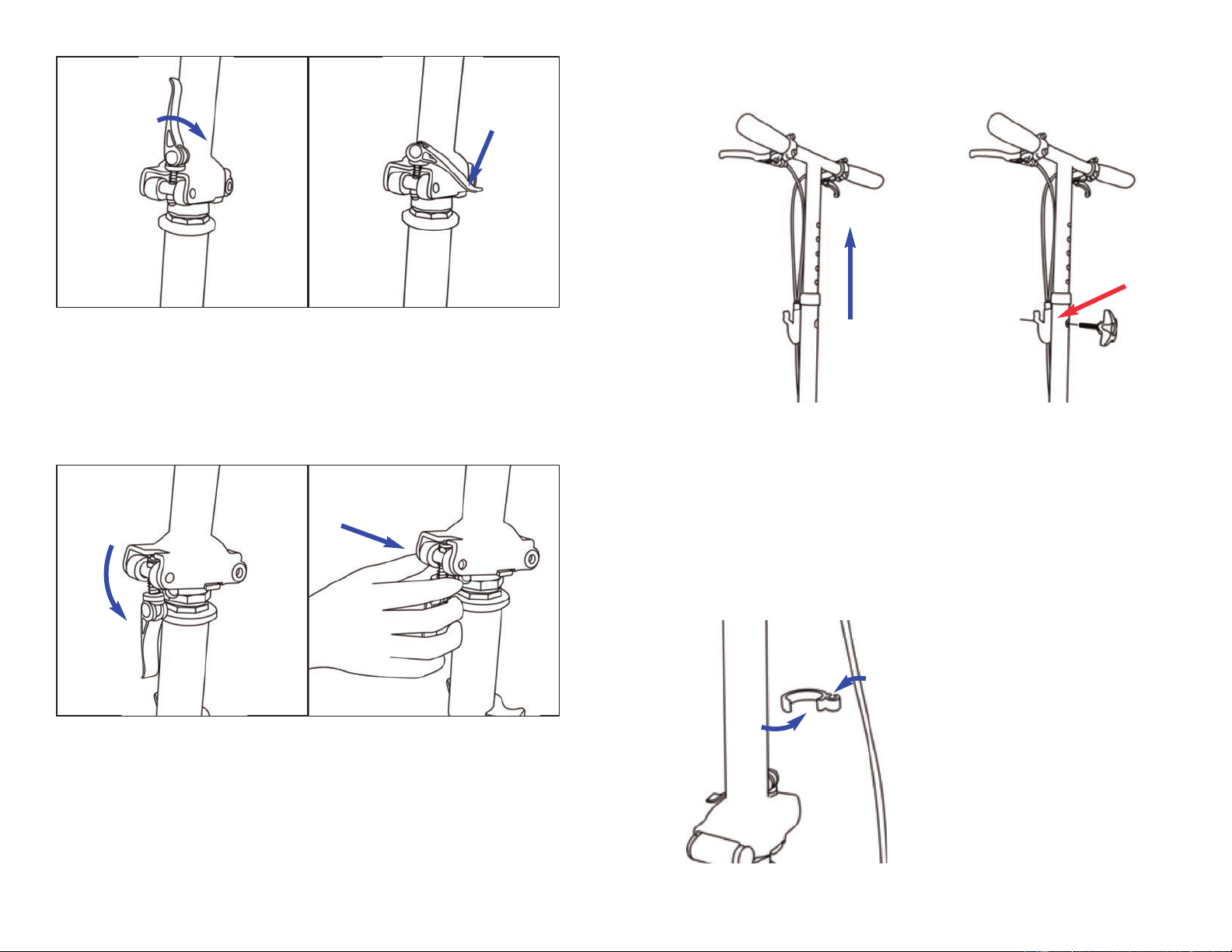
ATTACHING HANDLE HEIGHT ADJUST ENT KNOB
4a. locate the handlebar on top of the steering column post.
4b. Pull up the handlebar and extend the steering shaft up or
down to desired height. Align holes in tiller, then insert the
pentagram knob screw through the steering tiller. Tighten
pentagram knob by turning the knob clockwise to secure.
Handlebars should be set at wrist level to keep your back
straight.
4c. Use the included wire clip
to secure the loose brake
cable.

5a. nsert the seat post into the
mainframe of the knee walker, move
post up or down to desired height
5b. Align hole in the seat post with hole
on the mainframe, insert pentagram
knob through holes and tighten.
ATTACHING THE CALF PAD AND FOOT REST
6a. Locate the calf pad and slide the pad
mount onto the front foot rest post. The
wider side of the pad should be on top.
6b. Align the bottom hole of the
calf pad mount with the screw
hole on the foot rest. nsert the
heptagon knob through the holes
and secure in place.
6c. Slide the footrest pad onto
the other side of the footrest
post. Use the footrest pad for
rest when leg not paddling.
- 14 -- 13 -
ATTACHING THE SEAT POST TO THE AINFRA E
5c. Make sure the knob is screwed in
tightly to ensure security of the seat
pad in the scooter.

- 15 -
5a. Locate the basket for the
knee scooter from the package.
5b. Align the basket with the
plate located on the front of
the steering cast
5c. Push one side of the medal rod of the basket into the
steering shaft plate. Push the other side of the rod to secure.
ATTACHING THE POUCH
- 16 -
ADJUSTMENTS
ADJUSTMENTS
Always adjust the seat to the
lowest comfortable position to
propel with less effort. While
seated the user should be
able to maintain a bent knee
on the good leg.
SEAT HEIGHT ADJUST ENT
Turn the pentagram knob counter clockwise to remove,
extend the platform post shaft up or down to desired height.
Align holes in tiller, then insert the pentagram knob screw
through the steering tiller. Tighten the pentagram knob by
turning it clockwise to secure.

- 17 -
Seat Pad Angle Adjustment
To adjust the angle of the seating, use the included 13mm
open end wrench. First loosen the 2 black nuts under the seat
on both sides; position seat to desired angle and re-tighten.
Seat Pad Extension Adjustment
The seat can be extended 2” back for taller users. First,
loosen the black nut under the seat to remove the seat from
the seat mounting post. Flip the post mount receptacle toward
the front of the seat. Then, re-insert the seat onto the mounting
post and tighten.
Standard Length
Extended Length
SEAT ANGLE AND DISTANCE ADJUST ENT
- 18 -
ADJUSTING THE HEIGHT OF THE HANDLE
Locate the pentagram knob connecting the handle to the
steering shaft and remove it from the steering shaft.
The handle of the knee scooter has multiple holes for height
adjustment. Adjust the handle of the scooter to the prefered
height by pushing it down pulling it out and secure with the
pentagram knob.
Indice
Altri manuali Tuffcare Ausilio alla mobilità


