Tut Systems XL-12000B Manuale utente

USER GUIDE
XL-12000B
High-Speed Network Modem
TUT SYSTEMS

XL-12000B
HIGH-SPEED NETWORK MODEM
TUT SYSTEMS i
Warranty Policy
Warranty Summary
This Tut Systems product is warranted against defects in material and workmanship and will substantially
conform to Tut Systems product documentation for a period of one (1) year from the date of shipment.
Y2K Compliance
The Company’s products, including separately sold software applications, are designed to be used prior
to, during, and after the calendar year 2000 and will operate during each such time period without error
relating to date data, specifically including any error relating to, or the product of, date data which repre-
sents or references different centuries or more than one century.
Tut Systems will, at its option, either repair or replace products that prove to be defective. For warranty
or repair, return this product to a service facility designated by reseller in accordance with reseller
instructions which such instructions shall be in accordance with those set forth in Tut Systems Standard
Terms and Conditions of Sale.
Limitations of Warranty
The foregoing warranty shall not apply to defects resulting from abuse, neglect by Buyer, improper
installation or application by Buyer, Buyer-supplied software or interfacing, unauthorized modification
or misuse, operation outside of the environmental specifications for the product, acts of God, or improp-
er site preparation or maintenance.
Note: No other warranty is expressed or implied by statute or otherwise, regarding the product
including their fitness for any purpose, their quality, their merchantability, non-infringement or oth-
erwise.
Exclusive Remedies
The remedies provided herein are the buyer’s sole and exclusive remedies. Tut Systems shall not
be liable for any direct, indirect, special, incidental, or consequential damages, whether based
upon contract, tort, or any other legal theory. Warranties apply only to original purchaser or end-
user and cannot be assigned or transferred to subsequent parties. Tut Systems Standard Terms
and Conditions of Sale contain the full text of the product limited warranty.
Assistance
For assistance, contact your nearest Tut Systems Sales and Service office.
FCC Radio Frequency Interference Statement
This equipment has been tested and found to comply with the limits for a computing device, pursuant to
Part 15 of FCC Rules. These limits are designed to provide reasonable protection against harmful inter-
ference when the equipment is operated in a commercial environment. This equipment generates, uses
and can radiate radio frequency energy and, if not installed and used in accordance with the instructions,
may cause harmful interference to radio communications. However, there is no guarantee that interfer-
ence will not occur in a particular installation. If this equipment does cause harmful interference to radio
or television reception, which can be determined by turning the equipment off and on, the user is
encouraged to try to correct the interference by one or more of the following measures:
1. Reorient or relocate the receiving antenna.
2. Increase the separation between the equipment and receiver.
3. The equipment and the receiver should be connected to outlets on separate circuits.
4. Consult the dealer or an experienced radio/television technician for help.

ii TUT SYSTEMS
XL-12000B
HIGH-SPEED NETWORK MODEM
Changes or modifications not expressly approved by the party responsible for compliance could void the
user’s authority to operate the equipment.
The information contained in this publication is the latest available. However, Tut Systems reserves the
right to change specifications of hardware and software without prior notice. Purchasers of Tut Systems’
products should make their own evaluation to determine the suitability of each product for their specific
application. Tut Systems’ obligations regarding the use or application of its products shall be limited to
those commitments to the purchaser set forth in its Standard Terms and Conditions of Sale for a deliv-
ered product.
Published by Tut Systems, Inc.
2495 Estand Way
Pleasant Hill, CA 94523-3911
925-682-6510
fax 925-682-4125
www.tutsys.com
Copyright © 1998 by Tut Systems, Inc. All rights reserved.
No part of the contents of this manual may be reproduced or transmitted in any form or by any person
without written permission from the publisher.
Printed in the United States of America.
Tut Systems Manual P/N 220-03310-10 120798

XL-12000B
HIGH-SPEED NETWORK MODEM
TUT SYSTEMS iii
Contents
1.0 XL-12000B Product Overview 1
2.0 Technical Specifications 2
3.0 What’s in the Box 3
4.0 Installation 4
5.0 Panel Indicators and Connectors 7
5.1 Front Panel Indicators 7
5.2 Rear Panel Indicators and Connectors 9
6.0 Power and Boot Up Sequence 10
7.0 Troubleshooting 11
8.0 Technical Assistance and Customer Support 13
Appendix A: Pinout Assignments 14
Appendix B: Measuring Line Length 15
Figures
Figure 4.1 RJ-45 10 Base-T Straight-through Cable 4
Figure 4.2 RJ-11 DSL Line Cable 5
Figure 4.3 XL-12000B Installation with a Hub or Node 6
Figure 5.1 XL-12000B Front Panel 8
Figure 5.2 XL-12000B Rear Panel 9
Figure B.1 Using and Ohmmeter to Measure 15
the Length of Phone Wire
Tables
Table A.1 RJ-45 10Base-T Ethernet Connector 14
on Rear of Modem
Table A.2 RJ-11 DSL Line Connector on Rear of Modem 14

XL-12000B
HIGH-SPEED NETWORK MODEM
1.0 XL-12000B PRODUCT OVERVIEW TUT SYSTEMS 1
1.0 XL-12000B Product Overview
The XL-12000B modem is a high-speed, SDSL (Symmetrical
Digital Subscriber Line) point-to-point modem created to extend
Local Area Networks (LANs) up to 12,000 feet using ordinary
telephone wires. The modem uses Digital Subscriber Line (DSL)
transmission technology to deliver data at 2 Mbps.
The XL-12000B is designed for easy installation. Front panel LEDs
provide status and operational information. The modem is ideally
suited for connecting LANs in a campus environment where LANs
may be spread out over two miles. The XL-12000B units function
as a pair; one as Master and the other as Slave. The XL-12000B will
function as a bridge using Spanning Tree Protocol (STP) connecting
two independent segments. This mode allows the modem to pass
both IP and non-IP packets transparently making the segments a
single network. Examples of non-IP packets include Novell’s IPXTM
and Apple’s AppleTalkTM.

2.0 Technical Specifications
Data Rate: 2.048 Mbps
Line Length: Up to 12,000 ft. on 24 AWG wire
Up to 9,000 ft. on 26 AWG wire
Ethernet Interface: Compliant with IEEE 802.3 10Base-T
Operating Voltage: 120/240 VAC 50/60 Hz wall transformer
Power Consumption: 5 Watts
Operating Temperature: -5˚ to 55˚ C
Storage Temperature: -40˚ to +70˚ C
Relative Humidity: 5% to 90% (non-condensing)
Compliance: UL, CSA, CE, FCC Part 15 Class A
Software: Spanning Tree Protocol (STP) Bridging
(rfc-1493)
XL-12000B
HIGH-SPEED NETWORK MODEM
2TUT SYSTEMS 2.0 XL-12000B TECHNICAL SPECIFICATIONS

XL-12000B
HIGH-SPEED NETWORK MODEM
3.0 What’s in the Box
Confirm that there is one each of the following items:
Description
• XL-12000B Modem
• XL-12000B User Guide
• RJ-45 10Base-T Straight-through Cable
• RJ-11 DSL Line Cable
• Wall Transformer w/ Lightning Protection
3.0 WHAT’S IN THE BOX TUT SYSTEMS 3

4.0 Installation
1. Remove the modem and wall transformer from the shipping
carton. Remove the wall transformer from its box. Remove the
plastic wrapper from around the modem.
2. Remove the cable ties from each of the cables and place them
side by side.
Each of the cables is identified as follows:
(1) RJ-45 10Base-T straight-through cable: A cable with RJ-45
connectors is used to connect the modem to a 10Base-T
hub or node. If connecting to a node (PC, server or work-
station), the switch on the back of the modem will allow
this cable to be used like a cross-over cable (Figure 4.1).
Figure 4.1 RJ-45 10 Base-T Straight-through Cable
(2) RJ-11 DSL Line cable: A cable with RJ-11 connectors at
each end. RJ-11 connectors have four contacts and are
smaller than the RJ-45 connectors, which have eight contacts.
The diameter of the RJ-11 cable is smaller than the RJ-45
cable. This cable is used to connect the modem to the
telephone jack (Figure 4.2).
Note: RJ-11 cables generally have four contacts and six pinout
positions. The pinout assignments for the RJ-11 and RJ-45
connectors are provided in Appendix A.
XL-12000B
HIGH-SPEED NETWORK MODEM
4TUT SYSTEMS 4.0 INSTALLATION
181
2
3
6
1
2
3
6
81

XL-12000B
HIGH-SPEED NETWORK MODEM
Figure 4.2 RJ-11 DSL Line Cable
3. Select a convenient location near the Ethernet device to which
the modem will be connected. The modem should be kept away
from excessive heat or cold. Operating temperature range is
-5˚C to 55˚C.
4. Connect an RJ-45 straight-through cable from the 10Base-T
Ethernet connector of the XL-12000B to an Ethernet device (PC,
server, workstation or hub) as shown in Figure 4.3. If connecting
to a PC, server, or workstation, set the Ethernet connection
switch on the back of the modem to the “Crossed” position.
If connecting to a 10Base-T hub, set the switch to “Normal”.
5. Connect the RJ-11 DSL Line cable from the DSL connector on
the modem to the telephone jack.
6. Verify that you have a telephone line linking the two XL-12000B
modems. Verify that this line has no bridge taps and is generally
free of noise.
7. Connect the wall transformer as shown in Figure 4.3.
4.0 INSTALLATION TUT SYSTEMS 5
25
3
4
3
4
52
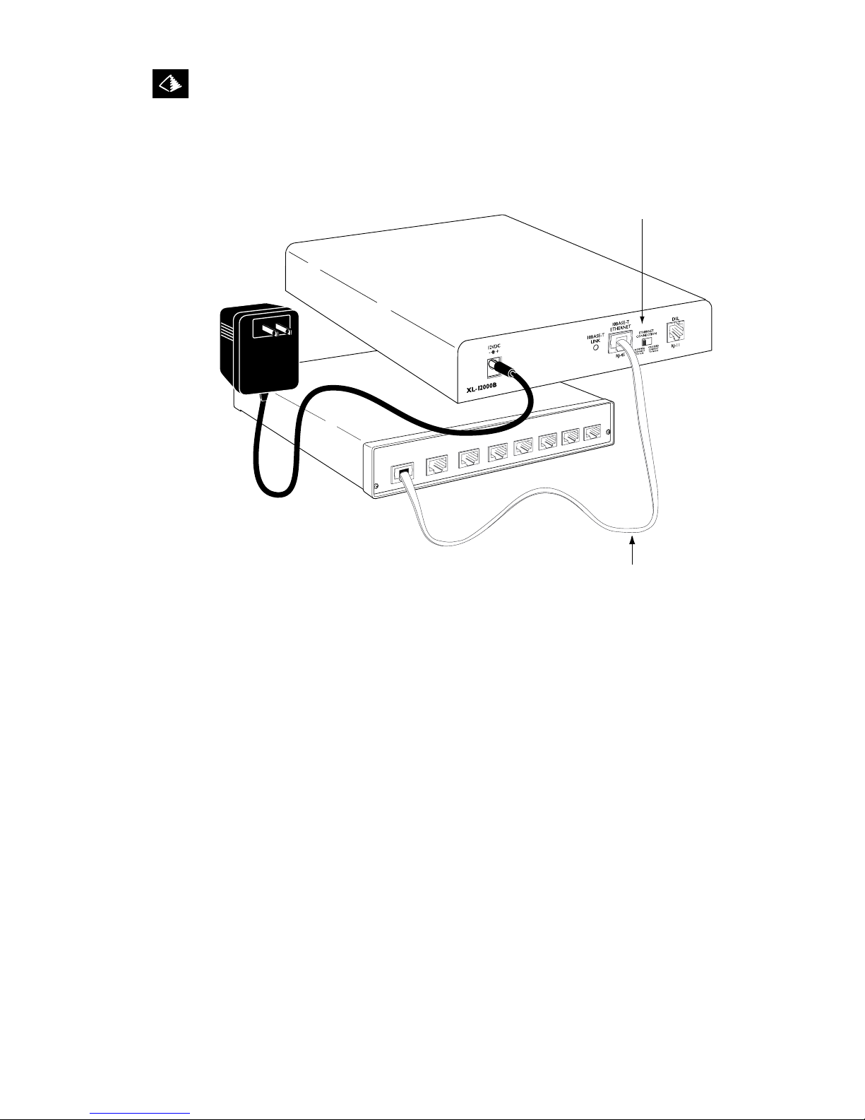
Figure 4.3 XL-12000B Installation with a Hub or Node.
Note: The Ethernet connection switch facilitates use with either type of device.
XL-12000B
HIGH-SPEED NETWORK MODEM
6TUT SYSTEMS 4.0 INSTALLATION
RJ-45
Straight-through
Cable
Ethernet Connection Switch
in Normal (Hub) Position
Indice
Altri manuali Tut Systems Modem


