TUYA TCLWRQS1 Manuale utente

TCLWRQS1 Datasheet
Hangzhou Tuya Information Technology Co., Ltd. 1 V2.0.0
1. Product Overview
TCLWRQS1 is a Wi-Fi module developed by Hangzhou Tuya Inc ,which takes the
communication with 5V TTL signal . It consists of a highly integrated RF chip (RTL8710BN)、
external Flash IC and DC-DC components, It embedded with Wi-Fi network protocol stack and
robust library functions,Besides it also contains with a low-power ARM-CM4 MCU, 2 MB flash
memory, 256KB SRAM, WLAN MAC,1T1R WLAN and rich peripheral resources.
1.1 Features
Embedded with32 bit CPU, which can be used as an application processor
Dominant frequency: up to 125 MHz
Working voltage: 5 V
Peripherals: 1*UART (5V TTL)
Wi-Fi connectivity
802.11b/g/n/HT20/HT40
Channels 1 to 14 at 2.4 GHz(Ch1-11 for US/CA,Ch1-13 for EU/CN)
WPA, WPA2, WEP, and TKIP security modes
Up to +17 dBm Avg output power in 802.11b mode
STA, AP, and STA+AP working modes
Smart and AP network configuration modes (for Android and iOS devices)
PCB On board antenna
Working temperature: –20°C to 85C
Tuya TCLWRQS1 Wi-Fi Module
Version: 2.0.0
Date: 2020-2-26 No:
Product
Manual
Global Intelligent Platform

TCLWRQS1 Datasheet
Hangzhou Tuya Information Technology Co., Ltd. 2 V2.0.0
1.2 Applications
Intelligent building
Smart household and home appliances
Industrial wireless control
Handheld device
Change History
No.
Date Change Description Version After Change
1 2020-2-25 First release. 2.0.0

TCLWRQS1 Datasheet
Hangzhou Tuya Information Technology Co., Ltd. 3 V2.0.0
Contents
1. Product Overview ............................................................................................................ 1
1.1 Features.................................................................................................................. 1
1.2 Applications ............................................................................................................ 2
2 Module Interfaces ............................................................................................................. 5
2.1 Dimensions and Footprint ...................................................................................... 5
2.2 Pin Definition .......................................................................................................... 6
2.3 Test Pin Definition ................................................................................................... 6
3 Electrical Parameters ........................................................................................................ 7
3.1 Absolute Electrical Parameters .............................................................................. 7
3.2 Electrical Conditions ............................................................................................... 7
3.3 RF Current .............................................................................................................. 8
3.5 Working Mode Current Consumptions ................................................................... 8
4 RF Features ...................................................................................................................... 9
4.1 Basic RF Features .................................................................................................. 9
4.2 Wi-Fi Output Power ................................................................................................ 9
4.3 Wi-Fi RX Sensitivity .............................................................................................. 10
5 Antenna Information ........................................................................................................ 10
5.1 Antenna Type .......................................................................................................... 10
5.2 Antenna Interference Reduction ................................................................................ 10
5.3 Antenna Connector Specifications ....................................................................... 11
6. Packaging Information and Production Instructions ...................................................... 11
6.1 Mechanical Dimensions ........................................................................................... 11
6.2 Production Instructions ......................................................................................... 11
7 MDQ and Packing Information ....................................................................................... 12
8 Appendix: Statement ....................................................................................................... 12

TCLWRQS1 Datasheet
Hangzhou Tuya Information Technology Co., Ltd. 4 V2.0.0
Figures & Tables
Figure 1 TCLWRQS1 front views......................................................................................... 5
Figure 2 TCLWRQS1 back views ........................................................................................ 5
Table 1 TCLWRQS1 interface pins ...................................................................................... 6
Table 2 TCLWRQS1 test pins .............................................................................................. 6
Table 3 Absolute electrical parameters ................................................................................ 7
Table 4 Normal electrical conditions .................................................................................... 7
Table 5 Current during constant transmission and transmitting .......................................... 8
Table 6 RX power consumption during constant receiving ................................................. 8
Table 8 Basic RF features.................................................................................................... 9
Table 9 TX power during constant emission ........................................................................ 9
Table 10 RX sensitivity ....................................................................................................... 10
Figure 3 TCLWRQS1 mechanical dimension .................................................................... 11

TCLWRQS1 Datasheet
Hangzhou Tuya Information Technology Co., Ltd. 5 V2.0.0
2 Module Interfaces
2.1 Dimensions and Footprint
TCLWRQS1 dimensions: 49.3mm±0.35mm(L)×30.8±0.35mm(W) ×7.8±0.15mm (H).
Note :(H) is the total height of Bottom surface components and Top surface components of
the transfer plate
Figure 1, Figure 2 shows the TCLWRQS1 dimensions.
Figure 1 TCLWRQS1 front views
Figure 2 TCLWRQS1 back views

TCLWRQS1 Datasheet
Hangzhou Tuya Information Technology Co., Ltd. 6 V2.0.0
2.2 Pin Definition
Table 1 describes the interface pins.
Table 1 TCLWRQS1 interface pins
No. Symbol
I/O Type Function
1 Vin P Power supply pin 5v input
2 GND P Power supply reference ground pin
3 TXD I/O TX port, output 5V TTL
4 RXD I/O RX port, input 5V TTL
Note: P indicates power-supply pins, I/O indicates input and output pins.
2.3 Test Pin Definition
Table 2 describes the test pins.
Table 2 TCLWRQS1 test pins
No. Symbol I/O Type Function
1 3.3V P Internal 3.3V Power pin for downloading and authorizing
2 GND P Internal GND pin
3 UART_Rx
I/O Used for authorization
4 UART_Tx
I/O Used for authorization
5 Log_Tx I/O Log Tx,Used for debugging to print the log information
6 Log_Rx I/O Log Rx,Used for debugging to print the log information
7
- Used for RF test
Note: Test pins cannot be used.

TCLWRQS1 Datasheet
Hangzhou Tuya Information Technology Co., Ltd. 7 V2.0.0
3 Electrical Parameters
3.1 Absolute Electrical Parameters
Table 3 Absolute electrical parameters
Parameter Description Minimum
Value
Maximum
Value
Unit
Ts Storage temperature –20 85 °C
VBAT Power supply voltage - 5.5 V
Static electricity voltage
(human body model)
Tamb = 25°C N/A 2 kV
Static electricity voltage
(machine model)
Tamb = 25°C N/A 0.5 kV
3.2 Electrical Conditions
Table 4 Normal electrical conditions
Parameter
Description Minimum
Value
Typical
Value
Maximum
Value
Unit
Ta Working temperature –20 N/A 85 °C
VBAT Power supply voltage 4.5 5 5.5 V
VIL IO negative level input -0.3 - VCC*0.25 V
VIH IO positive level input VCC*0.75 - VCC V
VOL IO negative level output - - VCC*0.1 V
VoH IO positive level output VCC*0.8 - VCC V
Imax IO drive current - - 12 mA

TCLWRQS1 Datasheet
Hangzhou Tuya Information Technology Co., Ltd. 8 V2.0.0
3.3 RF Current
Table 5 Current during constant transmission and transmitting
Working
Status
Parameter
Typical
Value Unit
Mode Rate TX Power
TX
802.11b 11 Mbit/s 18.76 dBm 270 mA
802.11g 54Mbit/s 17.48 dBm 255 mA
11n BW20/BW40 Mcs7 16.56dBm 235 mA
3.4 Wi-Fi RX Power Consumption
Table 6 RX power consumption during constant receiving
Symbol Mode Rate Typical Value Unit
IRF CPU Sleep
11 Mbit/s
90 mA
IRF CPU
Active
54 Mbit/s
120 mA
3.5 Working Mode Current Consumptions
Table 7. Working current consumption
Mode AT TA=25℃ Typical
Max*
Unit
EZ Mode Module is under EZ paring mode, wifi indicator
light flashes quickly
95 245 mA
AP Mode Module is under AP paring mode, wifi indicator
light flashes slowly
88 150 mA
Operation Mode
Module is connected, wifi indicator light is on 45 220 mA
Note:the above parameters are different according to the firmware functions.

TCLWRQS1 Datasheet
Hangzhou Tuya Information Technology Co., Ltd. 9 V2.0.0
4 RF Features
4.1 Basic RF Features
Table 8 Basic RF features
Parameter Description
Frequency band 2400 GHz to 2483.5 MHz
Wi-Fi standard IEEE 802.11b/g/n20 /n40(channels FCC:1-11 CE:1-13)
Data transmission rate
802.11b: 1, 2, 5.5, or 11 (Mbit/s)
802.11g: 6, 9, 12, 18, 24, 36, 48, or 54 (Mbit/s)
802.11n: HT20 MCS0 to MCS7
802.11n: HT40 MCS0 to MCS7
Antenna type Onboard PCB antenna
4.2 Wi-Fi Output Power
Table 9 TX power during constant emission
Parameter Minimu
m Value
Typical
Value
Maxim
um
Value
Unit
Average RF output power, 802.11b CCK mode
1
Mbit/s
N/A 18.76 N/A dBm
Average RF output power, 802.11g OFDM
mode
54
Mbit/s
N/A 17.48 N/A dBm
Average RF output power, 802.11n OFDM
mode
MCS7
N/A 16.65 N/A dBm
Frequency error –20 N/A 20 ppm
TCLWRQS1 Datasheet
Hangzhou Tuya Information Technology Co., Ltd. 10 V2.0.0
4.3 Wi-Fi RX Sensitivity
Table 10 RX sensitivity
Parameter Minimum
Value
Typical
Value
Maximum
Value Unit
PER < 8%, 802.11b CCK mode 1 Mbit/s N/A –90 N/A dBm
PER < 10%, 802.11g OFDM mode 54 Mbit/s
N/A –73 N/A dBm
PER < 10%, 802.11n OFDM mode MCS7 N/A –70 N/A dBm
5 Antenna Information
5.1 Antenna Type
TCLWRQS1 uses the onboard PCB antenna.
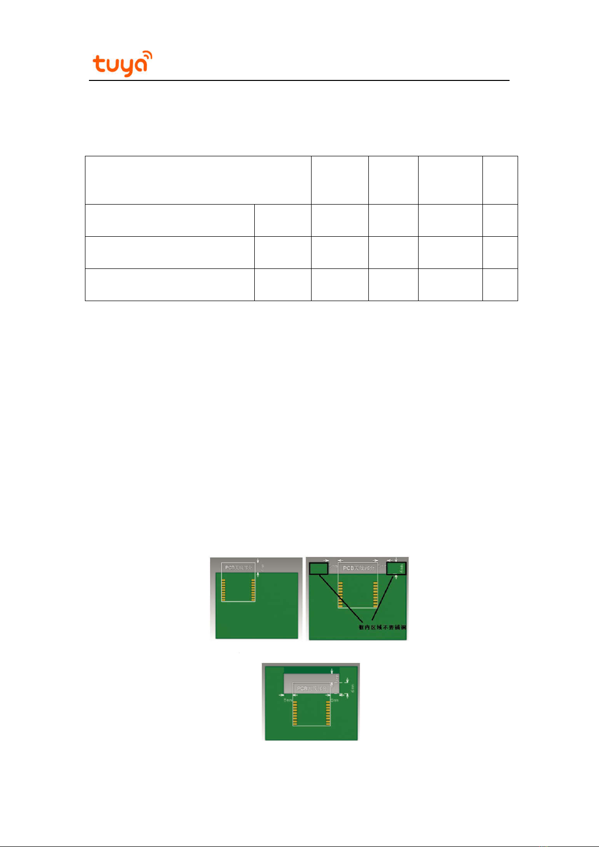
5.2 Antenna Interference Reduction
To ensure optimal Wi-Fi performance when the Wi-Fi module uses an onboard PCB antenna,
it is recommended that the antenna be at least 15 mm away from other metal parts.
To prevent adverse impact on the antenna performance, do not use copper or route cables
along the antenna area on the PCB.
For details about the onboard PCB antenna area on a module, see Figure 3.
Indice
Altri manuali TUYA Router wireless


