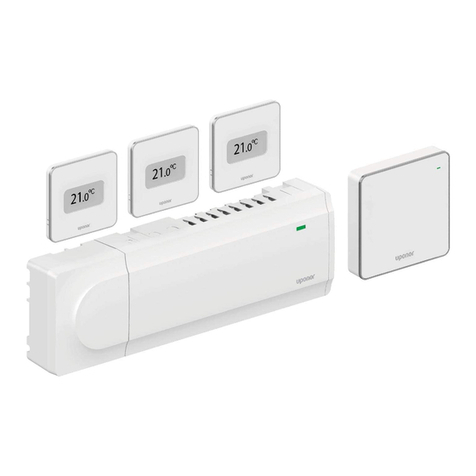
Uponor A3041501 Manuale utente

The Uponor Single-stage SetPoint
Controller with Floor Sensor (A3041501)
accurately controls the room and/or floor
temperature for a hydronic heating zone
using Pulse Width Modulation (PWM)
technology. Simple up and down buttons
and
a display with large type make
this thermostat easy to read and
use. An optional Uponor Floor
Sensor (A3040079) is included to measure
floor temperature to protect the floor from
overheating and enhance comfort.
Introduction
Energy-saving Features
• Auto Heating Cycle
Additional Features
• Radiant Floor Heating
• Pulse Width Modulation (PWM)
• Floor and Air Temperature Control
• Outdoor and Floor Temperature
Display
• Backlight
• Freeze Protection
• Includes Floor Sensor (A3040079)
Installation & Operation Manual
Single-stage SetPoint Controller
with Floor Sensor (A3041501)

2www.uponorpro.com
Congratulations on the purchase of your new Uponor thermostat.
This manual will step through the complete installation, programming and sequence of
operation for this control. At the back, there are tips for control and system troubleshooting.
Getting Started
Preparation
Installation
Table of Contents
Getting Started ...........................................2
Installation ..................................................2
Preparation ............................................2
Removing the Thermostat Base .............3
Mounting the Thermostat .....................4
Floor Sensor Installation ........................5
Floor Sensor Wiring ................................6
Floor Sensor Testing ..............................7
Temperature vs. Resistance Table .............. 7
Thermostat Wiring .................................9
Testing the Thermostat Wiring ............10
User Interface ............................................11
Home Screen .......................................11
Symbols Description ............................11
Sequence of Operation..............................12
Heating Operation ...............................12
Programmable Settings .............................13
Troubleshooting ........................................14
Error Messages ....................................14
Frequently Asked Questions ................15
Technical Data .....................................15
Improper installation and operation of this control could result in damage to the equipment
and possibly even personal injury or death. It is your responsibility to ensure that this control
is safely installed according to all applicable codes and standards. This electronic control is not
intended for use as a primary limit control. Other controls that are intended and certified as
safety limits must be placed into the control circuit.
Caution
• Jeweller screwdriver
• Phillips head screwdriver
• Wire stripper
Tools Required
--------------------------------------------

3
Single-stage SetPoint Controller Installation & Operation Manual
Choose the placement of the thermostats early in the construction process to enable proper
wiring during rough-in.
Consider the following:
• Install on an interior wall.
• Keep dry. Avoid potential leakage onto the control.
• Ensure relative humidity is less than 90% (non-condensing environment).
• Do not expose to extreme temperatures beyond 32-122°F (0-50°C).
• Do not expose to draft, direct sun, or other cause for inaccurate
temperature readings.
• Install away from equipment, appliances, or other sources of electrical interference.
• Ensure easy access for wiring, viewing, and adjusting the display screen.
• Install approximately 5 feet (1.5m) off the finished floor.
• The maximum length of wire is 500 feet (150m).
• Strip wire to 3⁄8" (10mm) for all terminal connections.
• Use standard, 4-conductor, 18-AWG wire.
Installation Location
----------------------------------------
Materials Required
-----------------------------------------
• 18 AWG LVT Solid Wire
(Low-voltage Connections)
Removing the Thermostat Base
To remove the thermostat base:
• Locate the tab on the bottom of the thermostat.
• Push the tab with either your thumb or with a
screwdriver.
• Lift the thermostat front away from the
thermostat’s base.

4www.uponorpro.com
Mounting the Thermostat
Wall
Thermostat
Front
Thermostat
Base
If mounting directly to the wall:
• Drill holes and install the wall anchors.
• Feed the wiring through the large hole in the thermostat base.
• Fasten the thermostat base to the wall using the wood screws to the wall anchors.
• Terminate wiring to the wiring strip.
• Push the thermostat front onto the thermostat base.
31/4"
(83mm)
Stud
Gang
Box
Thermostat
Front
Thermostat
Base
Adapter Plate
If a single gang box is used:
• Adapter Plate is required (sold separately).
• Feed the wiring through the hole in the adaptor plate and the thermostat base.
• Fasten the adaptor plate to the gang box.
• Fasten the base of the thermostat to the adaptor plate.
• Terminate wiring to the wiring strip.
• Push the thermostat front onto the thermostat base.

5
Single-stage SetPoint Controller Installation & Operation Manual
Thick Floor Coverings [greater than 3⁄8" (10mm)]
If installing a thick floor covering directly to the subfloor, a groove 1⁄8" (4mm) wide by 1⁄16"
(2mm) deep can be cut into the back of the flooring material to accommodate the wire for
the sensor. Ensure the sensor is located in such a position that the attached wire is able to
reach to a suitable junction location.
Avoid splices under the floor covering to ensure
trouble-free operation. Cut a groove 3⁄16" (5mm)
wide by 3⁄16" (5mm) deep by 13⁄4" (45mm) long to
accommodate the sensor. Locate the sensor midway
between the heating elements to ensure a proper
temperature reading.
Note: If it is not practical to cut a groove in the
surface covering, follow the installation method used
for thin floor coverings.
Floor Sensor Installation
Thin-set or Thin-pour Applications
If installing the floor covering over either a thin-set or thin-pour material of sufficient depth,
the floor sensor can be placed directly into either the thin-set material or the thin-pour
material and covered over. Ensure the sensor is
located in such a position that the attached wire is
able to reach to a suitable junction location. Avoid
splices within the thin set or thin pour to ensure
trouble-free operation. Locate the sensor midway
between the heating elements to ensure a proper
temperature reading.
Tiles
Thin Set
Hydronic
Pipe
Thin Floor Coverings [less than 3⁄8" (10mm)]
If installling a thin floor covering directly to the subfloor, a groove 1⁄8" (4mm) wide by 1⁄16"
(2mm) deep can be cut into the surface of the subfloor to accommodate the wire for the
sensor. Ensure the sensor is located in such a position that the attached wire is able to reach
to a suitable junction location. Avoid splices under the floor covering to ensure trouble-free
operation. Cut a groove 3⁄16" (5mm) wide by 3⁄16"
(5mm) deep by 13⁄4" (45mm) long to accommodate
the sensor. Locate the sensor midway between the
heating elements to ensure a proper temperature
reading.
Hardwood
Subfloor
Hardwood
Subfloor
New Installations
------------------------------------------

6www.uponorpro.com
Tile Floor Coverings
If installing a Floor Sensor (A3040079) into an existing tile floor with sufficiently large grout
lines, the sensor and wire can be installed in one of the grout lines between the tiles. Select
a low-traffic area of the floor that is midway between the heating elements for the sensor
location. Ensure the sensor is located in such a
position that the attached wire is able to
reach to a suitable junction location.
Avoid splices within the grout to ensure trouble-free
operation. Remove the
appropriate grout line and place the sensor and wire
in the floor. Re-grout the area.
Installing the Sensor to the Bottom of a
Subfloor
If installing the sensor to the bottom of a subfloor,
cut a piece of 1" (25mm) thick, rigid insulation into a
6" (150mm) by 6" (150mm) square.
Cut a groove 3⁄16" (5mm) wide by 3⁄16" (5mm)
deep by 13⁄4" (45mm) long into the insulation
to accommodate the sensor. Place the sensor
in the groove and sandwich the sensor
between the insulation and the subfloor.
Use a suitable fastening method to affix the insulation
to the subfloor.
Tiles
Thin-set
Subfloor
Subfloor
Retrofit Installations
----------------------------------------
Caution: Do not run sensor wires parallel to telephone or power cables. If the sensor wires
are located in an area with strong sources of electromagnetic interference, use shielded cable
or twisted pair or run the wires in a grounded metal conduit.
The Floor Sensor is supplied with 10' (3m) of cable. If a longer length is required, 24 AWG or
larger wire can be spliced onto the two wires from the sensor. The splices should be properly
soldered and protected in an accessible junction box. Follow the sensor testing instructions
given in this manual and then connect the wires to the control.
Floor Sensor Wiring

7
Single-stage SetPoint Controller Installation & Operation Manual
Floor Sensor Testing
A good-quality test meter capable of measuring up to 5,000 kΩ (1 kΩ = 1000Ω)
is required to measure the sensor resistance. In addition, measure the actual temperature with
either a good-quality digital thermometer, or if a thermometer
is not available, place a second sensor alongside the one to be tested and compare the
readings.
First, measure the room temperature using the thermometer. Disconnect the Sen and Com
wires from the thermostat. Using an electrical meter, measure the resistance of the Sen and
Com wires at the thermostat location. Using the Temperature vs. Resistance Table below,
estimate the temperature measured by the sensor. The sensor measurement and thermometer
readings should be close. If the test meter reads a very high resistance, there may be a broken
wire, a poor wiring connection or a defective sensor. If the resistance is very low, the wiring
may be shorted, there may be moisture in the sensor or the sensor may be defective. To test
for a defective sensor, measure the resistance directly at the sensor location. Once the test
has been completed, reconnect the Sen and Com wires to the thermostat.
Do not apply voltage to the temperature sensor terminals at any time as damage to the
sensor may result.
Temperature vs. Resistance Table
Temperature Resistance
°F °C
-50 -46 490,813
-45 -43 405,710
-40 -40 336,606
-35 -37 280,279
-30 -34 234,196
-25 -32 196,358
-20 -29 165,180
-15 -26 139,402
-10 -23 118,018
-5 -21 100,221
0 -18 85,362
5 -15 72,918
10 -12 62,465
15 -9 53,658
20 -7 46,218
Temperature Resistance
°F °C
25 -4 39,913
30 -1 34,558
35 2 29,996
40 4 26,099
45 7 22,763
50 10 19,900
55 13 17,436
60 16 15,311
65 18 13,474
70 21 11,883
75 24 10,501
80 27 9,299
85 29 8,250
90 32 7,334
95 35 6,532

8www.uponorpro.com
Temperature vs. Resistance Table - Continued
Temperature Resistance
°F °C
100 38 5,828
105 41 5,210
110 43 4,665
115 46 4,184
120 49 3,760
125 52 3,383
130 54 3,050
135 57 2,754
140 60 2,490
145 63 2,255
150 66 2,045
155 68 1,857
160 71 1,689
Temperature Resistance
°F °C
165 74 1,538
170 77 1,403
175 79 1,281
180 82 1,172
185 85 1,073
190 88 983
195 91 903
200 93 829
205 96 763
210 99 703
215 102 648
220 104 598
225 107 553

9
Single-stage SetPoint Controller Installation & Operation Manual
Thermostat Wiring
Zone Valve
-----------------------------------------------
Zone Control Module A3031003/A3031004
------------------------
Relay
---------------------------------------------------
C
518 RRh W1 S1 Com
No Power
CRRh W1 S1 Com
No Power
Zone
Valve
24 V (ac)
Transformer
L N
R C
Floor Sensor (A3040079)
C
518 RRh W1 S1 Com
No Power
C
518 RRh W1 S1 Com
No Power
24
3
CRRh W1 S1 Com
No Power
Floor Sensor (A3040079)
Zone Control Module
A3031003/A3031004
Install field
jumper wire
R to Rh
C
518 RRh W1 S1 Com
No Power
RC
2
1
8
7
3
4
5
6
CRRh W1 S1 Com
No Power
L
NG
115 V (ac)
Floor Sensor (A3040079)
Relay
Transformer
Install field
jumper wire
R to Rh
Install field
jumper wire
R to Rh

10 www.uponorpro.com
Multiple Pump Relay (A3080301)
-------------------------------
Testing the Thermostat Wiring
Testing the Power
------------------------------------------
If the thermostat display turns on, this indicates that the thermostat is operating correctly and
there are no electrical issues. In the event that the display is permanently off:
1. Remove the thermostat front.
2. Use an electrical meter to measure voltage between the R and C wiring terminals. For AC
power supplies, the voltage should measure between 10 to 30 V (ac).
For DC power supplies, the voltage should measure between 10 to 30 V (dc).
3. If the voltage on the R and C wire terminations is continuous and the thermostat display
is not on, the thermostat may have a fault. Contact your Uponor sales representative for
assistance.
If the thermostat display intially powers on but later shuts off intermittently, there may be a
short circuit from the W wire to ground, or the power supply is too small to power the load.
Testing the Heat Zone Output Wiring
----------------------------
1. Touch the
button and set the heating temperature above the current room temperature.
Make sure the display does not flash “Max” if using a floor sensor.
2. When the “Heat On” symbol appears on the display, use an electrical meter
to check for voltage on the W and C wires connected to the zone valve,
wiring center, relay or switching relay. The electrical meter should read
10 to 30 V (ac) or (dc).
3. If the W and C wires have voltage, check the zone valve, wiring center, relay or pump to
determine if the heat device is operating correctly.
Thermostat Wiring
C
518 RRh W1 S1 Com
No Power
RW
24 V
RW
HNXX HNHN NH
Com Switching Relay
Zone 1 Zone 2 Zone 3
Class 2
Transformer
RW
Zone 1 Zone 2 Zone 3
CRRh W1 S1 Com
No Power
Floor Sensor
(A3040079)
LN
Pump
Indice
Altri manuali Uponor Controllori

Uponor
Uponor Smatrix Wave X-165 Guida rapida

Uponor
Uponor Smatrix Base PRO X-147 Manuale utente

Uponor
Uponor Smatrix Base Pro Manuale utente

Uponor
Uponor Smatrix Base PRO X-147 Manuale utente

Uponor
Uponor Smatrix Base PULSE Manuale utente

Uponor
Uponor Smatrix Base PULSE Manuale utente

Uponor
Uponor Smatrix Base PULSE Manuale utente

Uponor
Uponor X-80 Manuale utente

Uponor
Uponor Smatrix Base Pro Manuale utente

Uponor
Uponor Smatrix Base PRO Controller X-147 Manuale utente