URC DMS-OUT Manuale utente

Order Number
: GETEC-C1-16-414
FCC Part 15 Certification
Test Report Number
: GETEC-E3-16-052
Page 1 / 1
EUT Type: Stream Injector Output Device
FCC ID.: OZ5URCDMSOUT
APPENDIX G
: USER’S MANUAL


Universal Remote Control
DMS-OUT Owner’s Manual
Overview
The DMS-OUT allows 3rd party devices access to the streaming sources in
the DMS Audio Network. For example, this device is the perfect solution for
adding any new/existing 3rd party AVR, soundbar, or other audio device to
the DMS Audio Network.
Online Help:
www.urccontrolroom.com
For software downloads, training materials, and frequently asked questions.
Contact Support:
Total Control is a URC product sold through Authorized Dealers, for
questions or assistance contact you Custom Installer/Programmer (write in
the company name, email, and contact info):
or URC Technical Support at: [email protected]
Universal Remote Control, Inc.
500 Mamaroneck Ave
Harrison, New York 10528
Toll Free: (800) 901-0800
Main: (914) 835-4484
Table of Contents
Features and Benefits.........................................1
Parts & Pieces......................................................1
Requirements......................................................1
Rear Panel............................................................2
Top Panel & LED States......................................4
Bottom Panel.......................................................5
Wiring the DMS-OUT..........................................6
Page 1
Features and Benefits
The DMS-OUT is loaded with features to provide the perfect audio experience. Enjoy features such as:
●3rd Party Audio Device Integration
DMS-OUT grants 3rd party devices the ability to use sources that are available in the DMS Audio Stream.
●Audio Sensing Capability
The DMS-OUT, similar to the URC Audio Sensor (SEN-AUD), can detect an audio signal which can then trigger n activity (macro).
●Flexible Power Source
Use the supplied 5V DC power adapter or take advantage of the DMS-OUT’s PoE (Power Over Ethernet) capability using a CAT 5/6 wiring.
DMS-OUT Owner’s Manual
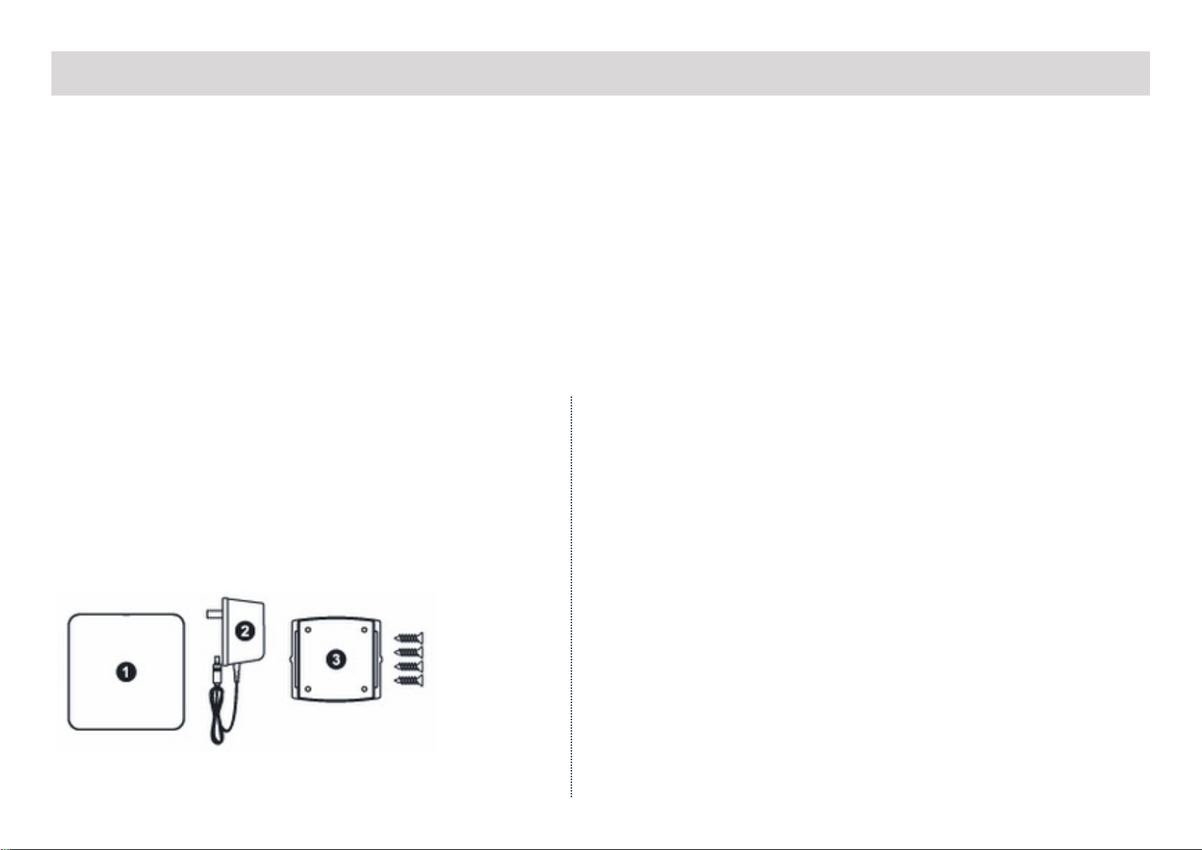
Parts & Pieces
Contained within the DMS-OUT box:
1. DMS-OUT Preamplifier Device
2. 5v DC Power Adapter
3. Wall Mount and 4x Screws
Requirements
As with all Total Control products, the DMS-OUT is not a
plug-and-play device. It requires programming by a
certified Total Control installer in order to work properly.
Be sure the system contains the following:
●MFS-8 or MFSPOE-8
●MRX-10 or MRX-8 Master System Controller
●URC User Interface (TRC-1080, TKP-7000, etc.)

Page 2
DMS-OUT Owner’s Manual
Rear Panel:
5V DC Input:
Provides power to the DMS-OUT. PoE may be used
as a substitute.
Analog Input:
Standard RCA (analog) connector.
Digital Input - Optical:
This input uses standard S/PDIF OPTICAL TOSLINK
connector.
Note: The DMS-OUT converts Dolby Digital 5.1/DTS 5.1
to a DMS Stream.

Page 3
LAN Port:
This 10/100 Ethernet port supports PoE and sends
the URC Audio stream through the local network,
this is also how the DMS-OUT receives commands
and sends audio.
Note: The DMS-OUT does not support Wi-Fi
Digital Input - Coax:
Standard RCA (analog) connector, this receives
bitstreams of audio data.
Note: The DMS-OUT converts Dolby Digital 5.1/DTS 5.1
to a DMS Stream.
DMS-OUT Owner’s Manual
Page 4
DMS-OUT Owner’s Manual
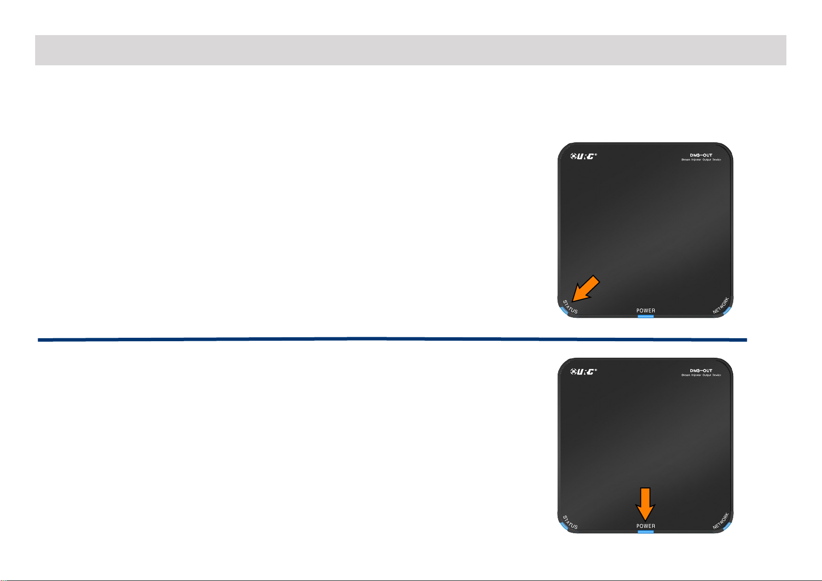
Top Panel & LED States:
There are three (3) LED lights at the top of the DMS-OUT which can provide users with basic troubleshooting information.
Status LED
●Off
Unit has not been programmed with a Total Control file.
●Yellow
Unit has been programmed with a Total Control file; however, is not creating
a DMS Audio Stream.
●Blue
Unit has been programmed with a Total Control file and is creating a DMS
Audio Stream through the network.
Power LED
●Off
Unit is not receiving power.
●Blue
Unit is receiving power via 5V DC adapter or PoE.

Page 5
DMS-OUT Owner’s Manual
Network LED
●Off
Unit is not connected to the local area network and cannot send/receive data.
●Blinking Green
Unit is connected to the local network, but has not received an IP address.
●Green
Unit is connected to the local network and has an IP address.
Bottom Panel
Located beneath the DMS-OUT is a Reset button. The Reset button is recessed so a
paperclip or something similar is required to press. This button allows for:
●Rebooting the DMS-OUT
A momentary press of the Reset button reboots the DMS-OUT, similar to
unplugging it from the power supply.
●Factory Default
Pressing and holding the Reset button for ten (10) seconds or longer, factory
resets the DMS-OUT to its factory state. The DMS-OUT requires re-programming
after this has been performed.

Page 6
DMS-OUT Owner’s Manual
Wiring the DMS-OUT
In order for the DMS-OUT to provide the best possible experience, it must be first wired correctly then programmed by a Total Control Certified
Installer. Follow these steps to prepare the DMS–IN for programming:
1. Power the DMS-OUT with the supplied 5V DC adapter OR PoE using the LAN port (see below)
2. Connect and Ethernet cable from the LAN 10/100 port to an MFS-8/MFSPOE-8
●The 5V DC adapter is not required when using PoE
3. Connect the DMS-OUT to a 3rd party device via Analog or Digital that is to be a part of the DMS Audio Stream
Additional set up is required via the URC Accelerator software. Contact a Certified Total Control Installer to properly configure the DMS-OUT to a
new or existing system.
OR
Only one source can be used at a time, further audio
adjustments can be made from within Accelerator.

Specifications
Microprocessor: Cortex-A5 600MHz
Memory: 128MB NAND, 128MB RAM
Network: One 10/100 Ethernet port (PoE)
Weight: 5.8oz
Size: 4.6” x 4.6” x 1.2”
Power: Standard PoE Injector or PoE Switch (purchased separately), DC 5V/1A
Page 7
DMS-OUT Owner’s Manual
Altri manuali per DMS-OUT
1
Indice

