Vacon nxsp Manuale utente
user's manual
nxs/p frequency converters
lonworks®
option board
opt-c4
Archived Document

INDEX
1. GENERAL ...........................................................................................................................3
2. LonWorks OPTION BOARD TECHNICAL DATA....................................................................4
2.1 General ............................................................................................................................................4
2.2 Physical media and wiring ..............................................................................................................5
2.3 Profiles.............................................................................................................................................6
3. LonWorks FIELDBUS BOARD LAYOUT AND CONNECTIONS ..............................................7
3.1 LonWorks OPT-C4 option board ..................................................................................................... 7
3.2 Grounding of bus cable shield in OPT-C4.......................................................................................8
3.3 Bus termination resistors ............................................................................................................. 10
3.4 LED indications.............................................................................................................................. 10
4. INSTALLATION OF VACON NX LonWorks BOARD............................................................. 12
4.1 Board information sticker............................................................................................................. 14
5. COMMISSIONING.............................................................................................................. 15
5.1 Fieldbus board parameters .......................................................................................................... 15
5.2 Start-up test .................................................................................................................................. 16
6. LonWorks INTERFACE ..................................................................................................... 17
6.1 General .......................................................................................................................................... 17
6.2 Input Network Variables ............................................................................................................... 19
6.3 Output Network Variables............................................................................................................. 22
6.4 Network Configuration Variables .................................................................................................25
6.5 Process data.................................................................................................................................. 27
7. FAULT TRACKING............................................................................................................. 28
8. APPENDIX 1......................................................................................................................29
Archived Document
general vacon • 3
24-hour service: +358-40-8371 150 • Email: vacon@vacon.com 1
1. GENERAL
Vacon NX frequency converters can be connected to the LonWorks® network using a fieldbus board.
The converter can then be controlled, monitored and programmed from the Host system.
The LonWorks® board shall be installed in slot E on the control board of the frequency converter.
LONWORKS technology has been developed by Echelon Corporation. LONWORKS network is used in
applications like industry and building automation, controlling household electronics, medical
instrumentation and many others. The target of the LONWORKS network is to provide a common
vendor independent communication network for intelligent devices.
In a LONWORKS network, no central control or master-slave architecture is needed. Nodes on a
network communicate with each other using LonTalk® protocol. Interoperable nodes use Standard
Network Variable Types (SNVT) for communicating over the network. The definition of an SNVT
includes units, a range, and an increment. Vacon option board uses only Standard Network Variable
Types for the data types.
All network variables are either input (data is coming from the network to the device) or output (data
is sent to the network by the device) network variables. When network variables on different nodes on
the network have been bound together by an installation tool, passing of data is automatic between
the right nodes. Only the same type of network variables can be bound together, so it is very
important to have compatible interfaces.
WARNING!
Internal components and circuit boards are at high potential when the frequency
converter is connected to the power source. This voltage is extremely dangerous
and may cause death or severe injury if you come into contact with it.
Archived Document
4 • vacon technical data
Tel: +358-201-2121 • Fax: +358-201-212 205
2
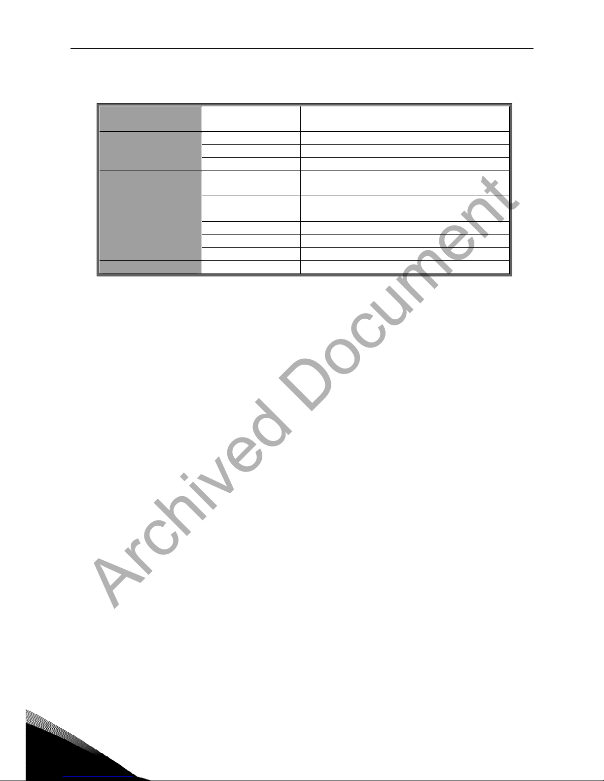
2. LONWORKS OPTION BOARD TECHNICAL DATA
2.1 General
LonWorks
connections
Interface Pluggable connector (5 mm)
Channel type TP/FT-10
Transfer cable Twisted pair
Communications
Baud rate 78 Kbit/s
Ambient operating
temperature
–10°C…50°C
Storing
temperature
–40°C…70°C
Humidity <95%, no condensation allowed
Altitude Max. 1000 m
Environment
Vibration 0.5 G at 9…200 Hz
Safety Fulfils EN50178 standard
Table 2-1. LonWorks technical data
Archived Document
technical data vacon • 5
24-hour service: +358-40-8371 150 • Email: vacon@vacon.com 2
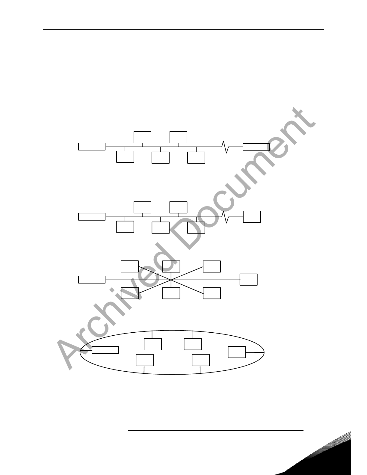
2.2 Physical media and wiring
LONWORKS networks can be implemented on many different physical media. Vacon OPT-
C4 option board is equipped with an FT-X1 transceiver supporting the Free Topology
transformer coupled network, which allows the network wire to be connected as bus,
star, loop or combination of these. This media reaches a communication speed of
78kBits/s. The FT-X1 transceiver is compatible with Echelon’s LPT-10 Link Power
Transceiver, and these transceivers can communicate with each other on a single
twisted pair cable.
termination termination
Figure 2-1. Doubly Terminated Bus Topology
termination
Figure 2-2. Singly Terminated Bus Topology
termination
Figure 2-3. Star Topology
termination
Figure 2-4. Loop Topology
Up to 64 FTT-10 transceiver nodes are allowed per network segment, the individual segments
can be connected together by a router. See Table 3-1 for recommended cable types and cable
lengths for FTT-10. Even if unshielded cable types are recommended to be used with this type
of transceiver, it is still highly recommended to use only shielded cables with frequency
Archived Document
6 • vacon technical data
Tel: +358-201-2121 • Fax: +358-201-212 205
2
converters. Attention should be paid to proper grounding of the shield to ensure bus
operation. Grounding of the shield should be done at both ends of the cable.
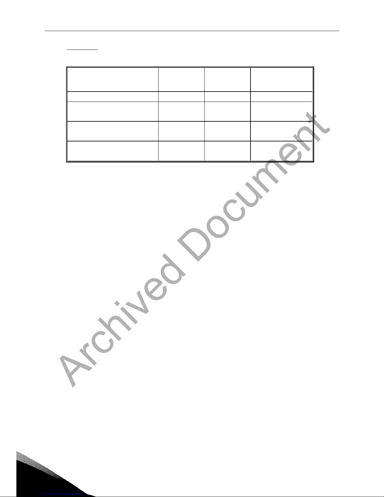
Cable type
Max. doubly
terminated
bus length
Max. free
topology
wire length
Max. node-to-node
distance
Belden 85102 (unshielded) 2700 m 500 m 500 m
Belden 8471
LONAK 2x1,3 (unshielded)
2700 m 500 m 400 m
Level IV, 22AWG
LONAK 2x2x0,65 (unshielded)
1400 m 500 m 400 m
JY (St) Y 2x2x0.8mm
LONAK 2x2x0,8 (shielded)
900 m 500 m 320 m
Table 2-2. Line length for different transmission speeds
2.3 Profiles
LonMark Functional Profiles describe in detail the application layer interface, including the network
variables, configuration properties, and default and power-up behaviors required on LonMark devices
for specific, commonly used control functions.
2.3.1
Variable Speed Drive Profile
Leading manufacturers of drive technology have jointly defined the LonMark profile. The profile
specifies how the drives are to be parameterized and how the setpoints and actual values are to be
transmitted. This enables drives from different vendors to be exchanged. The profile contains
necessary specifications for speed control and positioning. It specifies the basic drive functions while
leaving sufficient freedom for application-specific expansions and further developments.
Archived Document
layout and connections vacon • 7
24-hour service: +358-40-8371 150 • Email: vacon@vacon.com 3
3. LONWORKS FIELDBUS BOARD LAYOUT AND CONNECTIONS
Vacon LonWorks Fieldbus Board is connected to the fieldbus through 3-pin pluggable bus connector.
The communication with the control board takes place through the standard Vacon Interface Board
Connector.
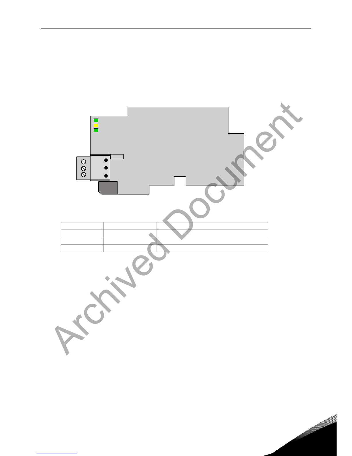
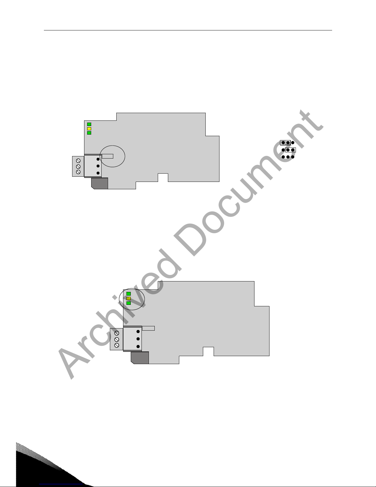
3.1 LonWorks OPT-C4 option board
Figure 3-1. Vacon LonWorks option board OPT-C4
Signal Connector Description
A1 21 Data
A2 22 Data
0Shield 23 Shield
Table 3-1. OPT-C4 bus connector signals
21
22
23
H3
H2
H1
X5
lw1.fh8
Archived Document
8 • vacon layout and connections
Tel: +358-201-2121 • Fax: +358-201-212 205
3
3.2 Grounding of bus cable shield in OPT-C4
The bus cable shield can be grounded to the frame of the frequency converter through an RC filter
located on the OPT-C4 board.
Note: Normally, the option board has already been installed in slot E of the control board. It is not
necessary to detach the whole board for the grounding of the bus cable shield. Just detach the
terminal block.
3.2.1
Grounding the bus cable shield directly to the frequency converter frame using the RC-
filter
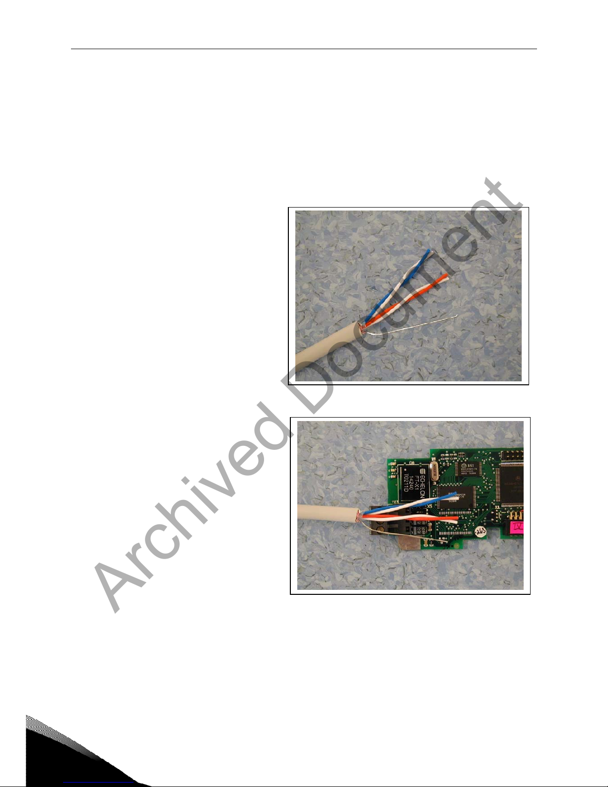
1 Strip about 5 cm of the cable as
shown in the picture.
Figure 3-2.
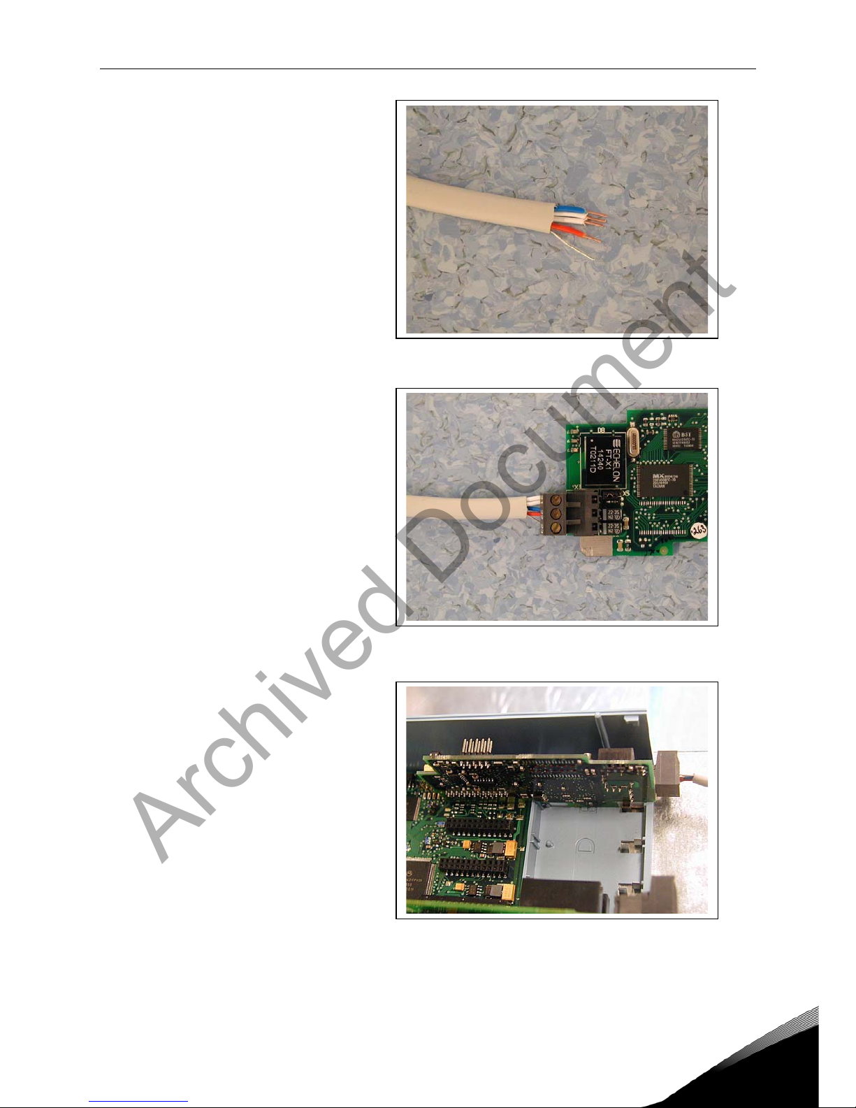
2 Leave no more than 7 mm of the
data cable outside the terminal
block (Figure 3-3) and strip the data
cables at about 5 mm to fit in the
terminals (Figure 3-4).
Figure 3-3.
Archived Document
layout and connections vacon • 9
24-hour service: +358-40-8371 150 • Email: vacon@vacon.com 3
Figure 3-4.
3 Insert the data cables and the
shield in their respective
terminals. See Table 3-1.
Figure 3-5.
4 If the LonWorks board was
detached from the control unit
place it into slot E of the control
board (see board installation on
page 12). Otherwise attach the
terminal block. Fix the cable on
the frame with the clamp.
Figure 3-6.
Archived Document
10 • vacon layout and connections
Tel: +358-201-2121 • Fax: +358-201-212 205
3
3.3 Bus termination resistors
To assure a proper data transmission, termination of the network segments is required. Depending
on the type of network, either one or two terminations are necessary. Free topology network segment
requires only one termination whereas a doubly terminated bus topology requires two.
The jumper X5 on the Vacon LonWorks board must be set accordingly. Use 94-ohm termination
resistance when only one termination is needed and 47-ohm for two terminations.
Figure 3-7. Using jumper X5 to set the bus termination.
3.4 LED indications
The three LED indications next to the connector show the present statuses of the Neuron (green H3),
the LonWorks board (yellow H2) and the Fieldbus Module (green H1). From the user's viewpoint, the
first two are the most significant.
Figure 3-8. LED indications on the LonWorks board
H3 Neuron Service LED GREEN
H2 Board Status YELLOW
H1 Bus Status GREEN
21
22
23
H3
H2
H1
X5
lw1.fh8
47Ω
94Ω
no termination X5
21
22
23
H3
H2
H1
X5
lw1.fh8
Archived Document
Altri manuali per nxsp
1
Indice
Altri manuali Vacon Convertitore multimediale

Vacon
Vacon NXL Manuale utente

Vacon
Vacon CXL Manuale utente

Vacon
Vacon CX Manuale utente

Vacon
Vacon NX Manuale utente

Vacon
Vacon alfiff28 Manuale utente

Vacon
Vacon CX Manuale utente

Vacon
Vacon NX series Manuale utente

Vacon
Vacon NX Manuale utente

Vacon
Vacon NX Liquid Cooled Manuale utente

Vacon
Vacon CX Manuale utente

Vacon
Vacon Vacon NX OPTC6 Manuale utente

Vacon
Vacon OPTC4 Manuale utente

Vacon
Vacon OPT-BE Manuale utente

Vacon
Vacon CX Manuale utente

Vacon
Vacon 20 Manuale utente

Vacon
Vacon 20 Manuale utente

Vacon
Vacon NXP Manuale utente

Vacon
Vacon X5OPT01 Manuale utente

Vacon
Vacon NXP Manuale utente

Vacon
Vacon CX Series Manuale utente


