
vds ITALO Documento tecnico

AUTOMATION
FOR BARRIERS
TECHNICAL INSTALLATION MANUAL
WARNING!! Before installing, thoroughly read this manual that is an integral
part of the pack
The CE mark conforms to European directive
EEC 89/336 + 92/31 + 93/68 D.L. 04/12/1992 N. 476.
Our products if installed by qualified personnel capable to evaluate risks,
comply with norms UNI EN 12453, EN 12445

PACKING CONTENTS ...................................................................... 2
TECHNICAL DATA............................................................................. 2
DIMENSIONS .....................................................................................
3
CONSIDERATIONS FOR INSTALLATION.........................................
3
INSTALLATION...................................................................................
4-5-6-7
TROUBLESHOOTING........................................................................
8
SAFETY PRECAUTIONS .................................................................. 12
Pag.
PACKING CONTENTS
1- BARRIER
1- BAR SUPPORT
TECHNICAL DATA
230V
Maximum length of bar 3 mt
Motors power supply 230Vac
Motor power 250 W
Motor RPM 1400
Condenser 16 µF
Mechanical unlock for emergency manoeuvre Mechanical
Working temperature -20° C / +55° C
Weight 45Kg
Protection rating IP 44
Limit switch Electromechanical
Opening time 3 sec
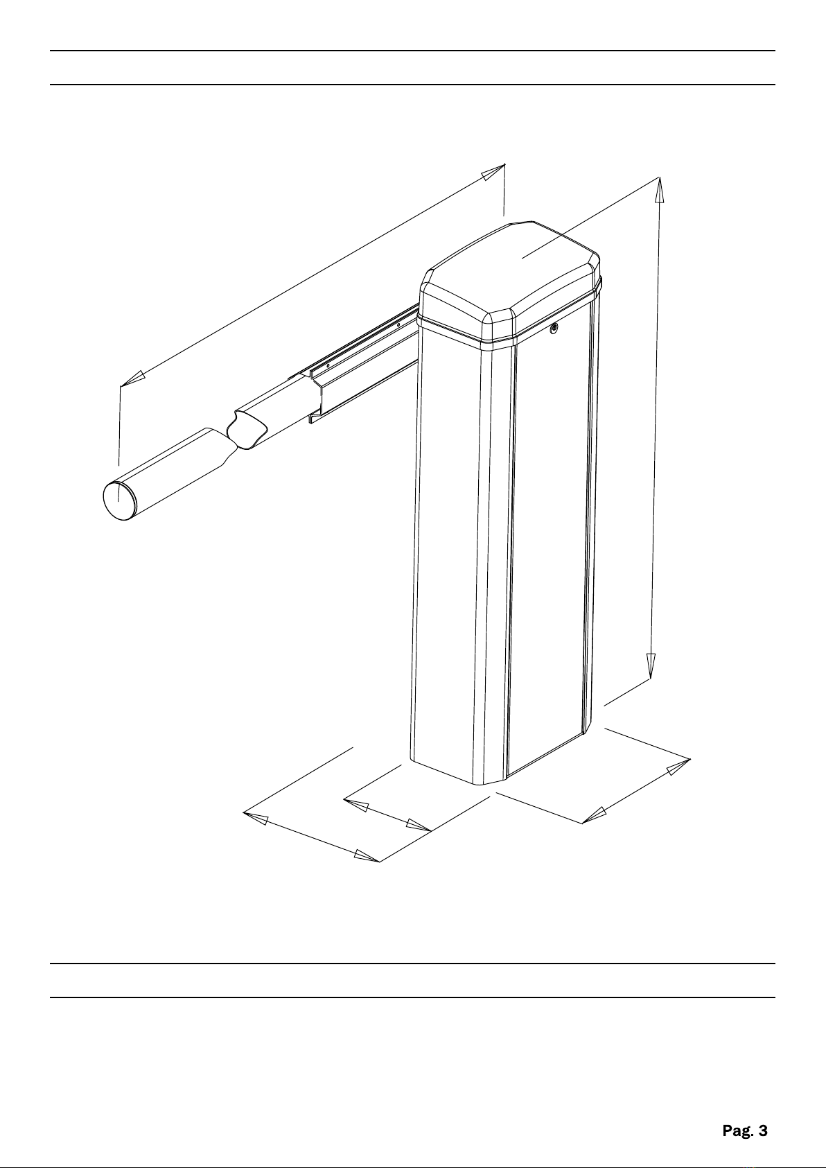
1070mm
MAX 3000mm
370mm
230mm
370mm
DIMENSIONS
CONSIDERATIONS FOR INSTALLATION
ŸThe installation and testing operations must be performed by qualified personnel
in order to guarantee the proper and safe operation of the automatic gate.
ŸThe company declines any responsibility for damage caused by incorrect
installations due to incompetence and/or negligence.

Nuts
INSTALLATION WITH BASE PLATE (OPTIONAL)
Take the floor plate and bend the brackets as needed. Dig a suitably sized hole in
the ground. Insert the electrical conduit into the cable conduit hole of the floor plate. Level
and cement the floor plate.
INSTALLATION
Set up an electrical multi-duct conduit in the middle of the foundation of the barrier,
corresponding to the central hole (corrugated - diameter 25 - 50mm).
Place the barrier on the floor
plate and fasten it with the
self-locking M12 nuts supplied.
Brackets
Base plate
Cable conduit
hole
INSTALLATION WITHOUT BASE PLATE
Place the barrier and block it through the four holes present internally on the basis.
1
2
3
4
Fixing holes

Monopole
Insert the key and open the cover.
Rotate the monopole located under the motor until reaching the desired opening.
Note: When you open the cover, the automation blocks.
MANUAL OPENING
SHAFT SUPPORT
Insert the bar support on the
shaft and fasten it with
screws
Insert the bar in the support
and tighten the screws Screw
Shaft
Screw
Key
Bar
support

OPENING DIRECTION
To change the opening direction of the automation from the left (standard) to the
right proceed as follows:
SX
DX
- Discharge the spring tension
- Unhook the spring
- Unhook the arm
- Reverse the position of the spring with the arm
- Hook again and tighten everything
- Invert the position of the key from position Ato Bof the output shaft.
- Reinsert the rod holder
A
A
BB
key
Front view
transmission shaft
Sprin
arm

SPRING REGULATION
ŸUnhook the arm
ŸPut on tension the spring by acting on
the adjusting nuts, until the rod remains
balanced at about 45°
ŸHook again the arm
Lower
nuts
Spring
adjustment
Tightening
nuts
Spring
adjustment
Arm
Microswitch
electric limit
switches
Adjustment screw
for the mechanical
limit switches
LIMIT SWITCHES REGULATIONS
It’s possible to adjust the limit switches
position, both the mechanical
(placed inside the barrier)
and electrical ones (easily accessible,
as they are placed under the superior
cover).
N.B. When one of the mechanical end-
stroke switches is repositioned, it is
necessary to relocate the
electronically controlled one
accordingly, and then repeat the stroke
selecting procedure

PROBLEM PROBABLE CAUSE SOLUTION
On giving a command with
the remote
control or with the
key-switch, the barrier
doesn’t open or the
motor doesn’t start
230 volt mains voltage
absent Check master switch
Emergency STOP present
Check for any STOP
selectors or commands.
If not used, check
jumper on STOP contact
input on the control board
Fuse blown Replace with one of same
value.
Power cable of motor or
motors not
connected or faulty.
Connect the cable to
appropriate
terminal or replace.
The photocell is not
functioning or the
beam is interrupted
Check the connection,
remove any
obstacle across the beam
On giving a command with
the remote control, the
barrier doesn’t open but
works with the key
command
The remote control has
not been
memorised or the battery
is flat
Carry out the remote
control learning
procedure on the radio
receiver or replace the
battery with a new one..
The barrier starts, but
stops immediately
The force of the motor or
motors is insufficient
Modify the value with the
FORCE trimmer on the
control unit
N.B. - If the problem persists, contact your Retailer or the nearest Service
Centre
TROUBLESHOOTING
All products are guaranteed for 2 years, as per the date on the invoice or on the receipt.
The warranty also does not include: failures or damages caused by faults of the electrical system
and/or carelessness, negligence or inadequacy of the installation to the use for which it is intended
and in any case from abnormal use; failures or damages due to tampering by unauthorized
personnel or the use of components not attributable to the manufacturer and/or non-original spare
parts; defects caused by chemical agents, external bodies or atmospheric and/or natural
phenomena in general; failures or damages caused by incorrect installation of the Products
according to the rule of art, safety and conformity of use expressly indicated in the technical
documentation of the same Products; the consumables; interventions for checks and assessments
of any flaws or defects then not found; compensations for the period of inactivity of the system
where the Products are installed.

NOTE

NOTE
Indice
Altri manuali vds Barriera automatica


