6
.www.velodyne.com HDL-64E User’s Manual
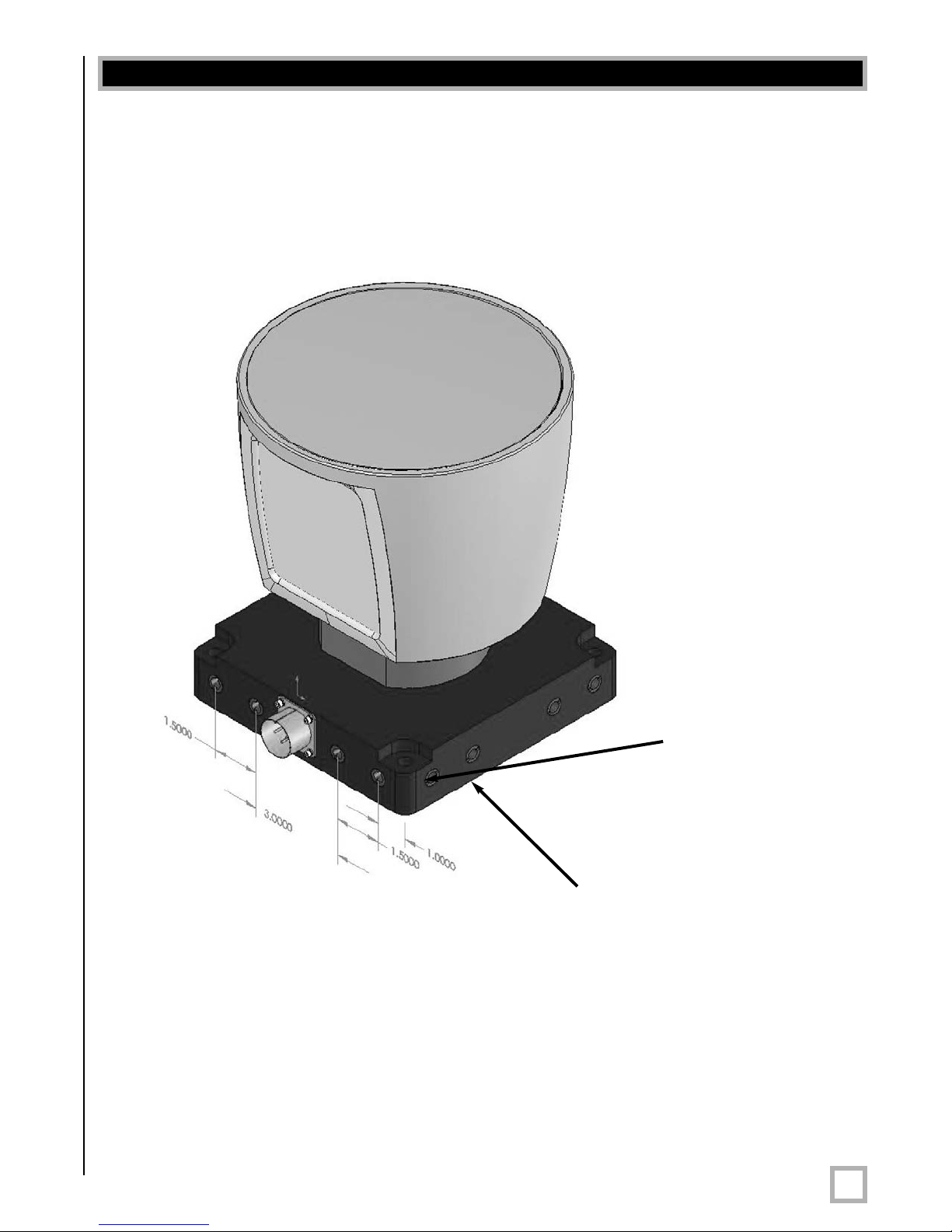
Wiring
The HDL-64E comes with a pre-wired connector, wired with power, DB9 serial, and standard
RJ-45 Ethernet connectors.The connector wires are approximately 25’ in length.
Power.Connect the red and black wires to vehicle power. Be sure red is positive polarity. THE
HDL-64E IS RATED ONLY FOR 12 VOLTS. Any voltage applied over 16 volts could damage the
unit. Expect the unit to draw 4-6 amps during normal usage.
NOTE: The HDL-64E does not have a power switch. It spins whenever power is applied.
The HDL-64E has a lockout circuit that prevents its lasers from firing at low RPMs.
Ethernet.This standard Ethernet connector is designed to connect to a standard PC. See the
next section on usage for UDP packet formats.
Serial Interface. The connector also features an RS-232 DB9 serial connector. This connector
allows for a firmware update to be applied to the HDL-64E (Velodyne may release firmware
updates from time to time). It also accepts commands to change the RPM of the unit.
Cable Diagram. If you wish to wire your own connector, refer to Appendix B for a layout of the
wiring pins.
Output
The HDL-64E outputs UDP Ethernet packets. Each packet contains a data payload of 1206
bytes that consists of 12 blocks of 100-byte firing data followed by six bytes at the end of each
packet that contains a spin counter and firmware version information. Each packet can be for
either the upper or lower laser banks (called “laser blocks”) - each bank contains 32 lasers.
The packet format is as follows:
2bytes of header info. This header indicates whether the packet is for the upper block
or the lower block. The upper block will have a header of 0xEEFF and the lower block
will have a header of 0xDDFF
.
2bytes of rotational info. This is an integer between 0 and 35999. Divide this
number by 100 to get degrees from 0.
32 laser returns broken into 3 bytes each. Each return contains two bytes of
distance information in .2 centimeter increments, and one byte of intensity information
(0 – 255, with 255 being the most intense return). A zero return indicates no return
up to 65 meters.
2bytes spin count (binary). This field is incremented for each revolution. After
65,535 revolutions, the counter resets to 0.
Note: The HDL-64E will ouput three upper block packets for every one lower block packet. This
provides more resolution when identifying objects at greater distances.
The minimum return distance for the HDL-64E is approximately three feet. Returns closer
than this should be ignored.
Usage