Vesta A SERIES Manuale utente

WASHING MACHINE
SERVICE MANUAL

2
INDEX
TECHNICAL FEATURES
COMPONENT SPECIFICATIONS
ENERGY LABEL
NAME PLATE
FAILURE CODES
AUTO TEST CHART
DETERGENT BOX GROUP WORK PRINCIPLE
CHILD LOCK MANUAL
AUTOTEST MANUAL
3
Component specifications
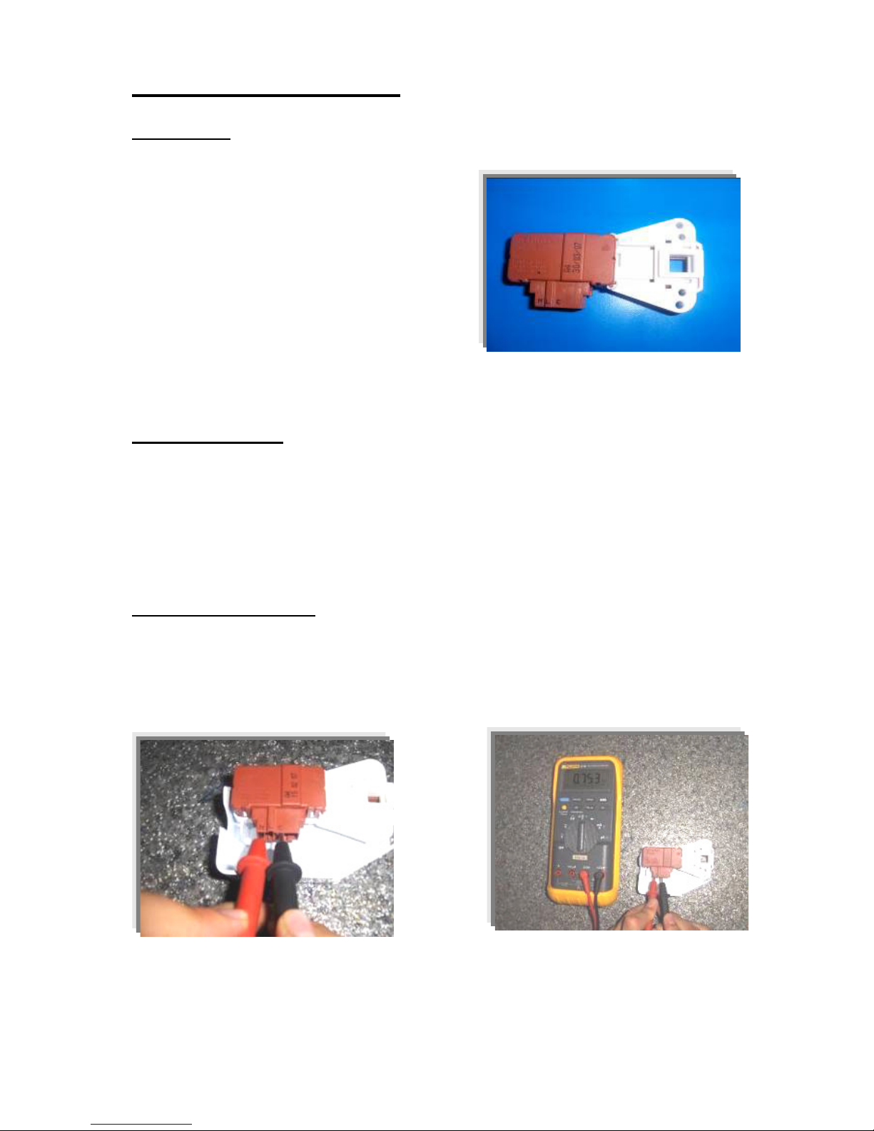
DOOR LOCK
Door lock is activated at the beginning of the program in
order to prevent the door from opening. It can be
unlocked approximately after 2 minutes of the program
end. This time delay is caused by the PTC which is
assambled in the door lock.
Figure 1. Door lock
Technical features :
Lock Time (20 °C) 2” – 6”
Unlock Time (20 °C) 35” – 75”
Nominal voltage 250 V
Nominal current 16 (4) A
Checking of component :
Check the resistance value on the component with multimeter as shown in Figure2.
Resistance value on the PTC should be 1000 Ω±50%.
Figure 2. Checking the component
4
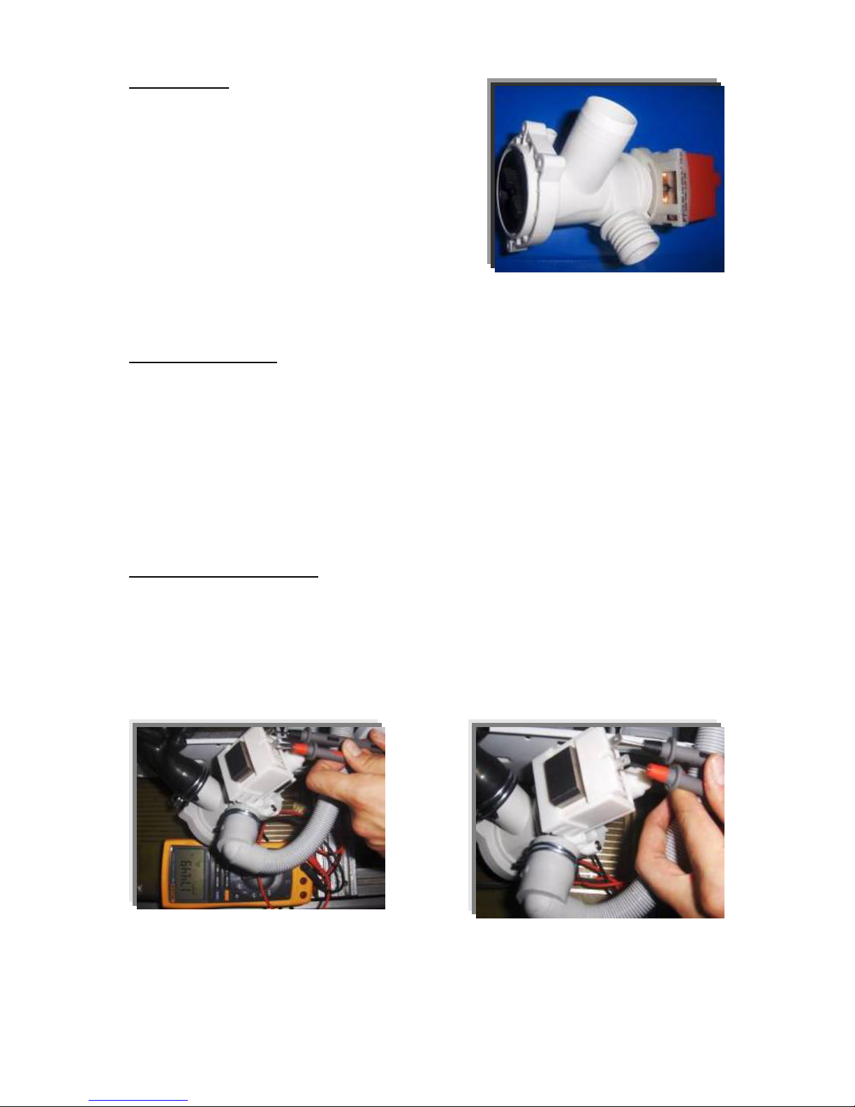
DRAIN PUMP
Drain pump is both a mechanical and elektrical component
which is used to drain water inside the washing machine. It
has an synchronous motor inside. For better performance
maintanance, pump filter should be cleaned regularly.
Figure 3. Drain pump
Technical features :
Nominal voltage 230 V
Nominal current 0.2 A
Nominal power 30 W
Frequency 50 Hz
Resistor (coil) 170 Ω(±7%)
Water flow: 18 l/min(to 1 m height)
Thermal protector YES
Checking of component :
Check the resistance value on the component with multimeter as shown in Figure 4.
Resistance value should be between 140- 200 Ohm
Figure 4. Checking the component
5
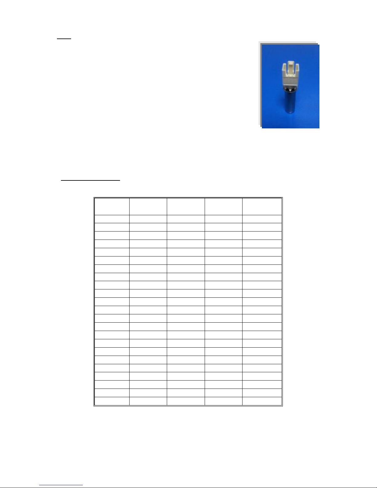
NTC
Component which sends signals to PCB about the water temperature inside
the tub. The Resistance (Ohm) value of the NTC decreases as the
temperature increases.
Figure 5. NTC
Techinal Feature :
Tem (°C) R nom (Ω)
Ω)Ω)
Ω)
R min
(Ω)
Ω)Ω)
Ω)
R max
(Ω)
Ω)Ω)
Ω)∆R (+/- %)
-10,00 58.722,00
54.874,00
62.570,00
6,60
- 5,00 45.778,00
42.961,00
48.596,00
6,20
0,00 35.975,00
33.900,00
38.050,00
5,80
5,00
28.516,00
26.977,00
30.055,00
5,40
10,00
22.763,00
21.616,00
23.910,00
5,00
15,00
18.279,00
17.421,00
19.137,00
4,70
20,00 14.772,00
14.128,00
15.417,00
4,40
25,00 11.981,00
11.497,00
12.464,00
4,00
30,00 9.786,00
9.421,00
10.150,00
3,70
35,00 8.047,00
7.772,00
8.322,00
3,40
40,00
6.653,00
6.444,00
6.861,00
3,10
45,00
5.523,00
5.365,00
5.680,00
2,80
50,00 4.608,00
4.489,00
4.726,00
2,60
55,00 3.856,00
3.767,00
3.945,00
2,30
60,00 3.243,00
3.178,00
3.308,00
2,00
65,00 2.744,00
2.681,00
2.808,00
2,30
70,00 2.332,00
2.273,00
2.392,00
2,50
75,00
1.990,00
1.934,00
2.045,00
2,80
80,00
1.704,00
1.653,00
1.755,00
3,00
85,00 1.464,00
1.416,00
1.511,00
3,20
90,00 1.262,00
1.218,00
1.305,00
3,40
95,00 1.093,00
1.053,00
1.133,00
3,70
100,00 949,90
913,20
986,60
3,90
Table 1 .NTC Tempure – Resistance Values

6
Checking of component :
Check the resistance value on the component with multimeter as shown in Figure 6.
Figure 6. Checking the component
7
EMI FILTER
EMI Filter Functions:
1. To adjust the frequency changes to the value of 50-60 Hz
which is the nominal frequency for the components.
2. To prevent harmonic frequency feedback sent by motor ,
resistance to the the network.
Figure 7. EMI Filter
Technical features :
Rated Voltage 250 V
Rated Current 16 A
Cx 0,47 µF (±20%)
Cy 2 x 25 nF (±20%)
L 2 x 1 mH (+%50,-%30)
R 680 kΩ (±10%)
Checking of component :
Check the resistance value on the component with multimeter as shown in Figure 8.
Resistance value on the EMI filter (between L-N polars) should be 680 kohm (±10%).
8
Figure 8. Checking the component
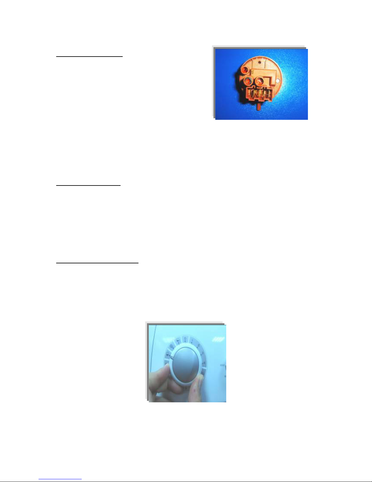
PRESSURE SWITCH
Voltage : 250 V
Amper :16 A
Figure 9. Pressure switch
Pressure switch is the component which regulates the water intake according to the water levels set
inside. The component is operated by PCB card. It has four connections : Reset, set, common,
overflow.
Technical features :
The component has three levels. When the component is at reset level, the machine begins to take
water inside. When the component is at set level, the machine stops to take water inside by
communicating with PCB card. The third level, overflow level, is set to prevent taking excessive
water(overflow) into the machine.
The pressure switches that have different water set levels have different water intake values
accordingly.
Checking of component :
1 ) Blow into the pressure switch hose or pressure switch entry. Be sure that you hear the switch click.
2 ) Turn the program adjustment knob rinse mode and let the machine take water in. Be sure that you
hear the switch click or the machine stops to take water inside after a while. (Figure 10.)
Figure 10. Program knob

9
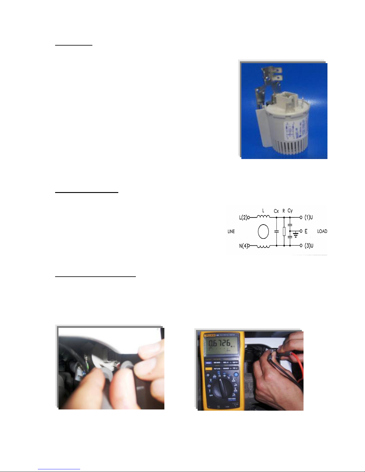
RESISTANCE
Heating element (Resistance) is a component which is
desingned to regulate temperature of water inside the
drum. It has three connections: Phase, notral and ground
connections.
Figure 11. Resistance
Technical features :
Kind of heating Tubular heating element with NTC – sensor
Nominal voltage 230 V
Nominal power 1850 W (±5%)
Resistance 26.96-29.80 Ω
Thermal fuse 2 – sided
Checking of component :
Check the resistance value on the component with multimeter as shown in Figure 12.
Resistance value should be between 25- 30 Ohm.
Figure 12. Checking the component
10
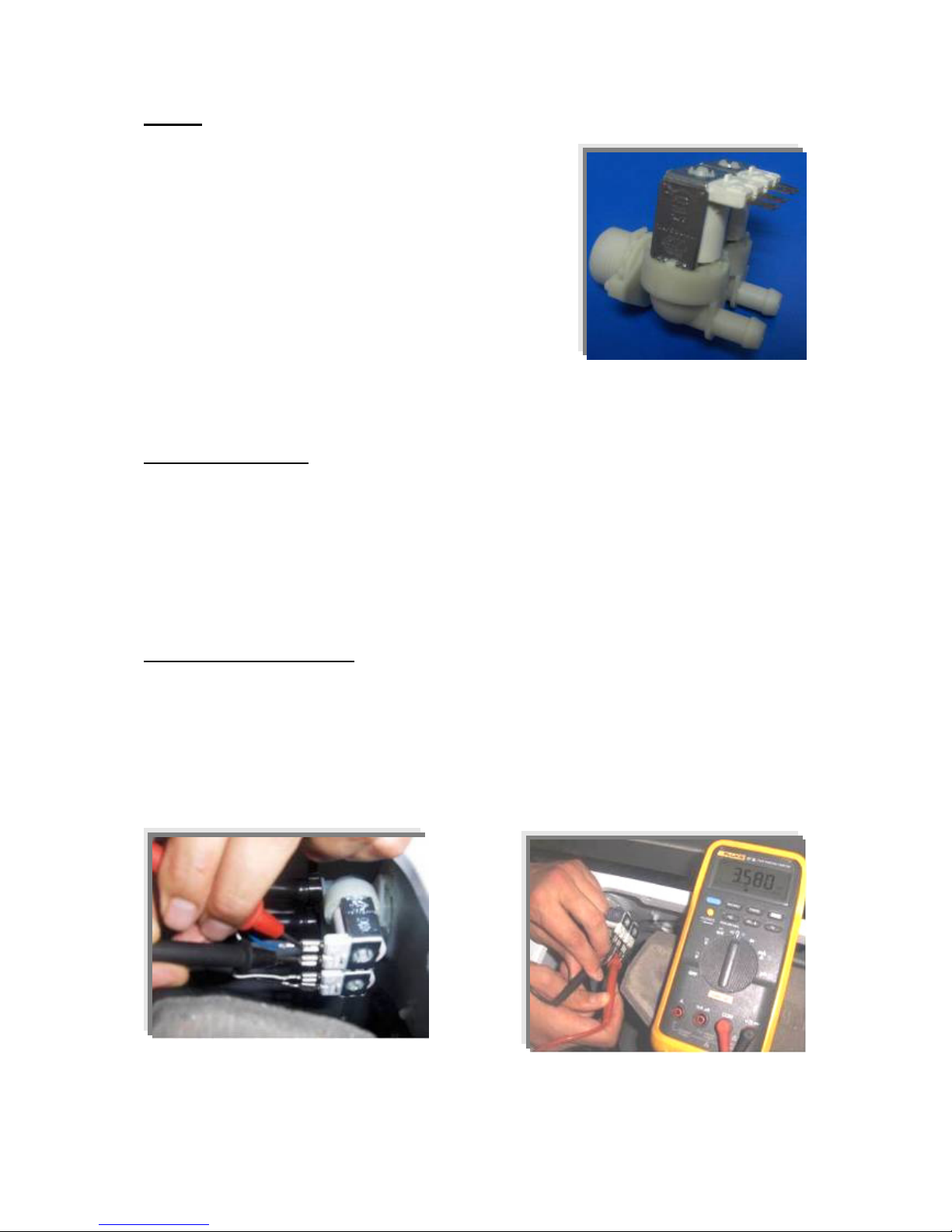
VALVE
Valve is an electrical and mechanical component which is
designed to take water from the network system into the washine
machine. It is operated by PCB card.
Figure 13. Valve
Technical features :
Nominal voltage 220 – 240 V
Nominal power 8 VA
Frequency 50 Hz
Rated flow: 6 1/min (±15%) (for cold inlet)
5.5 1/min (±15%) (for hot inlet)
Operating water pressure 0.2 – 10 bar
Checking of component :
Check the resistance value on the component with multimeter as shown in Figure 14.
Valve water flow rate should be between 6 - 8 lt/min.
Each valve bobbin resistance values should be between 3 - 4.5 kΩ.
Figure 14. Checking the component
Questo manuale è adatto per i seguenti modelli
1
Indice


