VGP OSSC Pro Manuale utente

OSSC Pro
Quick Start Guide
This document is copyright © VGP Media Ltd 2023
All rights reserved worldwide
VideoGameper ection.com is a trading name o VGP Media Ltd
Registered in Republic o Ireland number 637539

OSSC Pro Quick Start Guide VideoGamePer ection.com
OSSC Pro – Quick Start Guide
Contents
Important sa ety in ormation...........................................................................................................3
Overview..........................................................................................................................................4
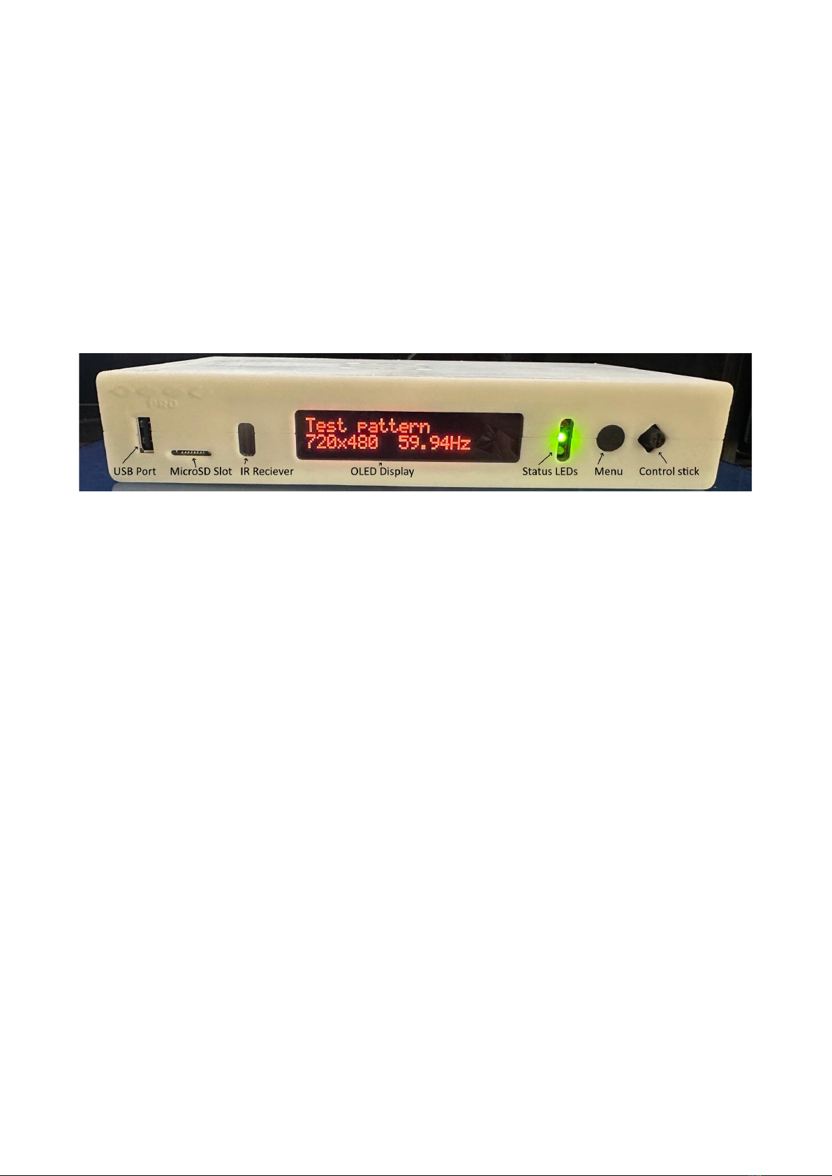
Connectors and external controls ( ront).....................................................................................4
Connectors (le t side)..................................................................................................................5
Connectors (Right side)..............................................................................................................5
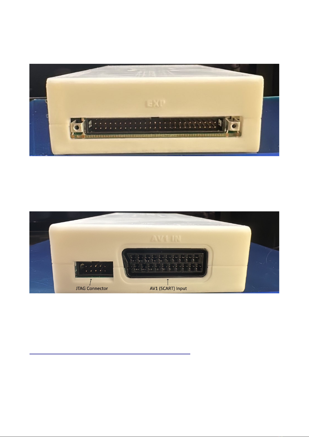
Connectors (Back).......................................................................................................................6
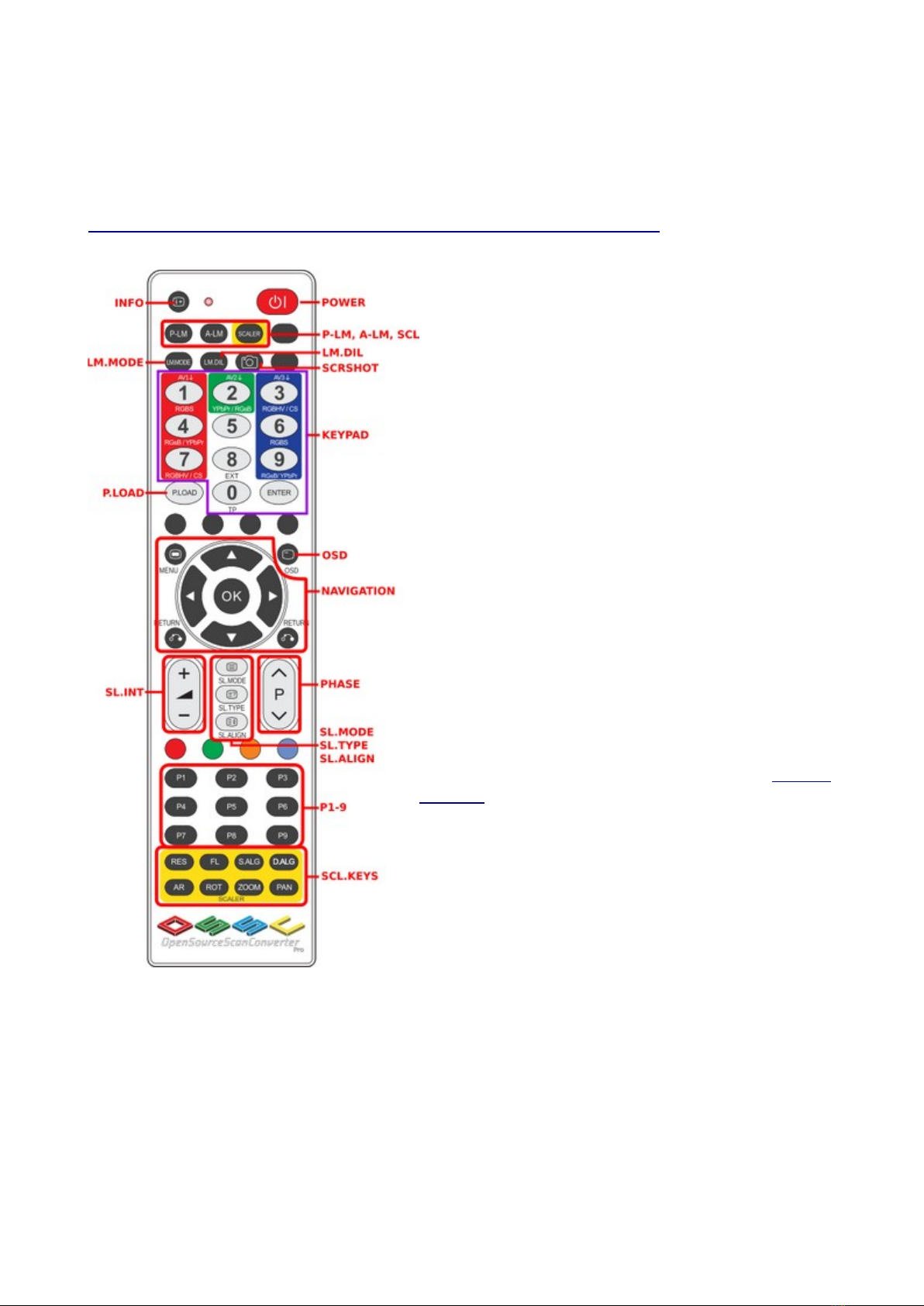
Remote control............................................................................................................................7
Connecting your OSSC Pro........................................................................................................8
Getting to know your OSSC Pro....................................................................................................10
One scaler, three modes............................................................................................................10
Changing modes........................................................................................................................12
Connecting consoles, PCBs or other hardware.........................................................................12
Scanlines...................................................................................................................................13
Setting output resolutions..........................................................................................................13
Framelock..................................................................................................................................15
Scaling algorithm......................................................................................................................15
Interlace video and the OSSC Pro.............................................................................................15
Fine tuning the image................................................................................................................16
Audio input and output.............................................................................................................16
Firmware updates...........................................................................................................................17
Troubleshooting.............................................................................................................................18
More in ormation......................................................................................................................19
Disposing o your OSSC Pro.........................................................................................................19
Thank you or purchasing the OSSC Pro. Please take time to read through this short document
be ore you start using the unit.
Page 2

Important safety information
Please observe the ollowing sa ety precautions when using your OSSC Pro.
Use the correct power supply – OSSC Pro is designed to run with a 5 volt, 2.1 x 5.5mm positive
tip power supply unit (PSU) supplying at least 2.5 amps o current. Please ensure your power
supply meets these requirements. Never connect a power supply that supplies more than 5 volts.
Doing so can damage the OSSC.
Turn off the power before connecting/disconnecting equipment – To prevent damage o the
OSSCs integrated circuits, always turn o the power be ore connecting to a display or a device.
Do not expose to moisture – Droplets o moisture may contact the PCB and cause a short circuit.
Never submerge the unit in water.
Keep away from fire or high heat sources – OSSC is not lammable but high temperatures, such
as those rom a ire or electric heater may melt the plastic casing.
Please supervise children – This product is not a toy and is not designed or use by children.
Please supervise children i they use the OSSC Pro.
eware of using the bob deinterlace mode on sources that display static graphics or text for a
long period of time – This deinterlacing mode produces a constant lickering e ect. This can cause
image retention/burn-in to occur aster than normal. Usually this applies to LCD TVs/monitors only,
CRT displays are not adversely a ected by this mode. We recommend using the scaler mode and
motion adaptive deinterlacing where possible, see page 15 or more details.

OSSC Pro Quick Start Guide VideoGamePer ection.com
Overview
OSSC Pro is a next generation video processor and scaler. The device is designed to take video
signals rom a range o older computers and video games consoles and convert and process these
signals so they are usable on modern, ixed resolution displays. While these modern displays are the
primary target o OSSC Pro, it also has the capability to convert newer video signals into ormats
that are more suitable or older displays, such as CRTs.
Connectors and external controls (front)
In the ront view picture you can see the ollowing eatures on your OSSC Pro.
US Port – For connecting and controlling external devices such as video switching hardware, or
connecting accessories (note, these eatures are not currently available but may be added in uture
irmware updates).
MicroSD Card Slot – For updating the devices irmware and storing display pro iles. See
“Firmware Updates” on page 17 or more in ormation.
IR Receiver – Receives commands rom the remote control unit. Line o sight is required.
OLED Display – Two line character display enables the user to navigate the OSSC Pro’s menus.
The display is particularly use ul i the user accidentally selects an incompatible output mode and
there ore cannot see the OSSC Pro’s on-screen menu.
Status LEDs – Indicate various unctions o the OSSC Pro. The top most LED will illuminate Red
when the OSSC Pro is in standby (all other LEDs will be o ). A Red and Green LED illuminated
together indicates an error condition with the current input. The middle LED will also blink when
an IR command is received.
Finally, the blue LED at the bottom illuminates when rame lock is active. Frame lock is discussed
on page 15.
Menu utton – Press this button to enter or exit the OSSC Pro’s menu. Press and hold this button
to toggle the OSSC between On and Standby.
Control Stick – Use the control stick to navigate through the OSSC Pro’s menus. Move the control
stick up, down, le t or right to navigate the menus. Click the control stick in to choose a menu
option. Press the Menu button to cancel your selection or exit the menus.
Page 4

Connectors (left side)
Expansion Connector – For adding expansion boards to the OSSC Pro. Expansion boards can add
new unctionality and input and output options.
Connectors ( ight side)
JTAG Connector - For so tware development purposes and irmware updates.
AV1 (SCART) Input – Connect an RGB SCART source to this input. Note the input must be RGB
or YPbPr, S-video and composite SCART sources are not supported and require transcoding into
RGB irst. Only European spec RGB SCART cables are supported, the less common Japanese JP21
cables must be used with a converter, a suitable one can be purchased here:-
https://videogameper ection.com/products/jp21-to-scart-adapter/

OSSC Pro Quick Start Guide VideoGamePer ection.com
Connectors (Back)
AV3 Audio input/output connector – This connector can be set to be an audio input (assignable to
AV1, AV2 or AV3) or as an audio output/break out rom AV1 SCART.
AV3 In – Standard D-Sub15 (VGA) connector. You can connect sources such as the Sega
Dreamcast or a retro gaming PC.
AV2 In – Connect component video or RGB with sync on green sources to this input.
AV2 Audio - Connect any analogue audio source to these two RCA connectors. This
audio input can be assigned to any video input.
SPDIF Input – For connecting high quality digital audio input rom compatible consoles or
devices. This audio input can also be assigned to any video input.
AV4 In – Connect a standard digital video source to this port. DVI sources will require an adapter.
Video Out – Connect a standard high de inition digital cable to this port and then connect the other
end o the cable to your television or monitor.
Power Connector – Connect a 5 volt, 2.1 x 5.5mm positive tip power supply unit (PSU) supplying
at least 2.5 amps o current. Note that use o the OSSC Classic power supply is not recommended
as it does not provide su icient amps or the OSSC Pro.
Page 6

emote control
The OSSC Pro uses a new, larger remote control to control all o its unctions. We will cover the
most important unctions in this guide, while you can learn about other eatures by visiting the
OSSC Pro Wiki page (https://junkerhq.net/xrgb/index.php?title=OSSC_Pro).
Info – Display in ormation about the current active
source and output mode.
Power – Toggles between On and Standby modes.
P-LM, A-LM, Scaler – Use these buttons to toggle
between the OSSC Pro’s three operating modes.
Keypad – Select the active input using these button
controls.
P.Load – Pro ile load. Use this button, ollowed by a
number on the keypad, to instantly load a display
pro ile.
Navigation – Use the Menu button to call up the OSSC
Pro’s menu. Use the directional arrows to navigate the
menu. Use the OK button to choose a menu option, or
enter a sub menu. Use the “Return” button to go back
up to the previous menu.
Scanline controls – Use these controls to adjust the
post processing scanlines, or to adjust image phase on
optimal pro iles. For more in ormation on this, consult
the wiki.
P1 to P9 – These buttons are reserved or uture use.
Scaler keys – These keys provide various shortcuts
when in scaler mode. The AR key can be pressed to
quickly select a new aspect ratio. The Zoom and Pan
buttons can be used to adjust the size o the image, or
move the image i it is o centre.

OSSC Pro Quick Start Guide VideoGamePer ection.com
Connecting your OSSC Pro
Connect a suitable power supply (5 volts, 2.5 amp positive tip) to the OSSC Pro’s power connector.
Connect a DVI or HDMI cable between the video out on the OSSC and your display. Almost any
display that supports HDMI or DVI-D can be used, but please remember some output modes do not
adhere ully to DVI/HDMI speci ications so compatibility cannot be guaranteed. For displays that
only have analogue inputs, a converter is required. OSSC Pro does not use HDCP, so any basic
converter should work.
Ensure the PSU is turned on at the wall, the red Standby light should then illuminate on the ront o
the unit. Power on your OSSC Pro using the power button on the remote control or by holding the
menu button on the ront o the unit. The OLED display on the ront o the unit should light up and
display “TP 480p”, as shown in the picture.
Switch your display to the correct input. I everything is working correctly, a grey test card pattern
should appear.
Page 8

Finally, power on your source device and press the Menu button on the OSSC remote. Use the
menu navigation buttons and OK to choose “Input Select” and then select the relevant input or
your console. For standard RGB SCART devices, choose “AV1_RGBS”. Component video sources
most commonly use “AV2_YpbPr”. VGA sources, such as a Sega Dreamcast, require
“AV3_RGBHV”. For digital video sources, choose “AV4”.
You should now see a picture rom your video device.
Congratulations, you have now set up your OSSC Pro and you can start experimenting with its
eatures.

OSSC Pro Quick Start Guide VideoGamePer ection.com
Getting to know your OSSC Pro
All settings or the OSSC Pro are con igured using the on-screen menu. To call up the menu at any
time, press the Menu button on the remote. The root or top level menu is shown below.
You can return to the top level menu at any time by pressing the “Return” button on the remote
(multiple presses may be required).
The menu is also shown on the ront OLED display, though navigating the menu on your
TV/monitor is usually easier and more convenient as more in ormation can be displayed.
One scaler, three modes
The OSSC Pro has three operating modes.
•Pure line multiplier
•Adaptive line multiplier
•Scaler
Pure and adaptive line multiplication modes o er a lag ree scaling solution or retro video
consoles, while the scaler mode o ers more lexible output options, at the expense o some input
lag.
We recommend users choose either adaptive line multiplication mode or scaler mode. Adaptive line
multiplication o ers many more options over the old, pure line multiplication that also eatured on
the classic OSSC. Theoretically, the pure line multiplication mode has slightly less input lag than
the adaptive mode, but in practise this di erence is so small that it is imperceptible. Re er to the
ollowing table or a summary o all the modes and their advantages and disadvantages.
Page 10
Indice
Altri manuali VGP Convertitore multimediale


