Viessmann WiFi module Manuale utente

Installation instructions
for contractors
VIESMANN
WiFi module
For installation in the Vitodens and Vitopend control unit support
WiFi module
5838175 GB 1/2019 Please keep safe.

2
Please follow these safety instructions closely to prevent accidents and
material losses.
Safety instructions explained
!Please note
This symbol warns against the
risk of material losses and envi-
ronmental pollution.
Note
Details identified by the word "Note"
contain additional information.
Installation, initial start-up, inspection,
maintenance and repairs must only be
carried out by a competent person
(heating engineer/installation contrac-
tor).
Before working on the equipment/heat-
ing system, isolate the power supply
(e.g. by removing a separate mains
fuse or by means of a mains isolator)
and safeguard against unauthorised
reconnection.
When using gas as fuel, also close the
main gas shut-off valve and safeguard
against unauthorised reopening.
Repairing components which fulfil a
safety function can compromise the
safe operation of your heating system.
For replacements, use only original
spare parts supplied or approved by
Viessmann.
Safety instructions
5838175

3
Installation sequence
Installing the WiFi module in the Vitodens........................................................... 4
■ Opening the Vitodens....................................................................................... 4
■ Opening the control unit enclosure................................................................... 5
■ Installing the WiFi module................................................................................. 6
Installing the WiFi module in the Vitopend........................................................... 7
■ Opening the control unit enclosure................................................................... 7
■ Installing the WiFi module................................................................................. 9
Starting up the WiFi module
Symbols on display in connection with WiFi module............................................ 11
Connecting the control unit to the WiFi................................................................ 11
■ Activating the WiFi module via key combination............................................... 11
■ Activating the WiFi module via the menu.......................................................... 12
■ Connecting the heating system to WiFi and the Viessmann server.................. 12
■ Symbols shown during operation...................................................................... 13
Troubleshooting................................................................................................. 14
Software licences............................................................................................... 17
Index
5838175
4
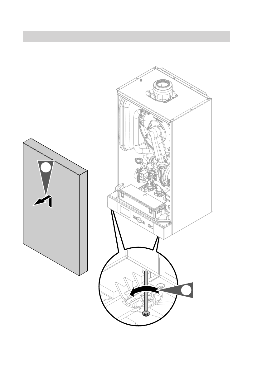
Opening the Vitodens
2x
2.
1.
Installing the WiFi module in the Vitodens
5838175

5
Opening the control unit enclosure
2x
1.
2.
4x
!Please note
Electronic assemblies can be
damaged by electrostatic dis-
charge.
Prior to commencing any work,
touch earthed objects such as
heating or water pipes to dis-
charge static loads.
Installing the WiFi module in the Vitodens (cont.)
5838175

6
Installing the WiFi module
X13 X11
4.
3.
1.
5.
X11
X10 X13
X111
T00
T00
T00
T00
T00
T00
T00
T00
T00
T00
T00
T00
T00
T00
T00
T00
T00
T00
T00
X13
X11
2.
1. Pull the dummy adaptor out down-
wards.
2. Remove the diaphragm grommet
and reinsert it with the cable.
Installing the WiFi module in the Vitodens (cont.)
5838175
7
3. Route the cable to terminals X11
and X13 on the PCB.
4. Plug connectors X11 and X13 into
the PCB. Insert the strain relief.
5. Connect the connector to the WiFi
module. Insert the WiFi module into
the control unit support from below.
6. Close the control unit enclosure
and the Vitodens in reverse order –
see pages 4 and 5.
7. Start up the WiFi module – see
page 11.
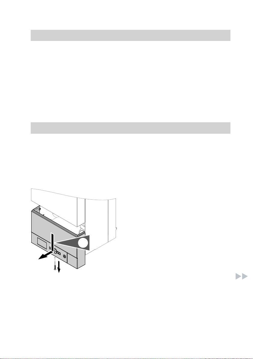
Installing the WiFi module in the Vitopend
Opening the control unit enclosure
!Please note
Electronic assemblies can be
damaged by electrostatic dis-
charge.
Prior to commencing any work,
touch earthed objects such as
heating or water pipes to dis-
charge static loads.
1.
1. Undo the screw and push the con-
trol unit downwards.
Installing the WiFi module in the Vitodens (cont.)
5838175

8
2.
2. Pivot the control unit forwards.
3. 2x
4.
3. Release the locking tabs on the
control unit enclosure.
4. Remove the wiring chamber cover.
Installing the WiFi module in the Vitopend (cont.)
5838175

9
Installing the WiFi module
4.
X13 X11
1.
X11
X10 X13
X111
T00
T00
T00
T00
T00
T00
T00
T00
T00
T00
T00
T00
T00
T00
T00
T00
T00
T00
T00
X13
X11
3.
2.
Installing the WiFi module in the Vitopend (cont.)
5838175

10
1. Pull the dummy adaptor out down-
wards.
2. Route the cable to terminals X11
and X13 on the PCB.
Insert the strain relief.
3. Plug connectors X11 and X13 into
the PCB.
4. Connect the connector to the WiFi
module. Insert the WiFi module into
the control unit support from below.
5. Close the control unit enclosure in
reverse order – see page 7.
6. Start up the WiFi module – see
page 11.
Installing the WiFi module in the Vitopend (cont.)
5838175
Indice


