ViewZ VZ-CMK03 Manuale utente
INSTALLATION INSTRUCTIONS
NORTH AMERICA
1220 N. Kraemer Blvd.
Anaheim, CA 92806 USA
USA and Canada
Phone: 1-888-99-ViewZ
Other Locations
Phone: (001) 714-630-3380
Fax: (001) 714-630-2335
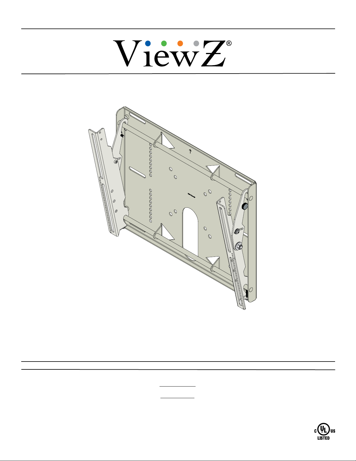
Tilting Wall Mount for 26˝to 40˝ViewZ Monitors
VZ-CMK03
853177002885
VZ-CMK03
Page 2 Visit the ViewZ website at http://www.viewzusa.com Installation Instructions
Contact ViewZ with any questions:
(888) 99-ViewZ
Contents
Warning Statements
Weight Limit
Maximum Flat Panel Weight: 160 lbs.
THE WALL STRUCTURE MUST BE CAPABLE OF
SUPPORTING AT LEAST FIVE TIMES THE WEIGHT OF
THE FLAT PANEL. IF NOT, THE WALL STRUCTURE MUST
BE REINFORCED.
PRIOR TO THE INSTALLATION OF THIS PRODUCT, THE INSTALLATION INSTRUCTIONS MUST BE READ AND
COMPLETELY UNDERSTOOD. KEEP THESE INSTALLATION INSTRUCTIONS IN AN EASILY ACCESSIBLE LOCATION
FOR FUTURE REFERENCE.
PROPER INSTALLATION PROCEDURE BY A QUALIFIED SERVICE TECHNICIAN MUST BE FOLLOWED, AS OUTLINED
IN THESE INSTALLATION INSTRUCTIONS. FAILURE TO DO SO COULD RESULT IN PROPERTY DAMAGE, SERIOUS
PERSONAL INJURY, OR EVEN DEATH.
SAFETY MEASURES MUST BE PRACTICED AT ALL TIMES DURING THE ASSEMBLY OF THIS PRODUCT. USE
PROPER SAFETY EQUIPMENT AND TOOLS FOR THE ASSEMBLY PROCEDURE TO PREVENT PERSONAL INJURY.
VIEWZ DOES NOT WARRANT AGAINST DAMAGE CAUSED BY THE USE OF ANY VIEWZ PRODUCT FOR PURPOSES
OTHER THAN THOSE FOR WHICH IT WAS DESIGNED OR DAMAGE CAUSED BY UNAUTHORIZED ATTACHMENTS
OR MODIFICATIONS, AND IS NOT RESPONSIBLE FOR ANY DAMAGES, CLAIMS, DEMANDS, SUITS, ACTIONS OR
CAUSES OF ACTION OF WHATEVER KIND RESULTING FROM, ARISING OUT OF OR IN ANY MANNER RELATING TO
ANY SUCH USE, ATTACHMENTS OR MODIFICATIONS.
At least two qualied people should perform the assembly procedure. Personal injury and/or property damage can result
from dropping or mishandling the at panel.
If mounting to wall studs or ceiling studs, make sure that the mounting screws are anchored into the center of the wall studs
or ceiling studs. Use of an edge-to-edge stud nder is recommended.
It is recommended that a maximum of ⅝˝ plaster board be used when mounting to wooden studs.
Be aware of the mounting environment. If drilling and/or cutting into the mounting surface, always make sure that there
are no electrical wires in wall. Cutting or drilling into an electrical line may cause serious personal injury.
Make sure there are no water or natural gas lines inside the wall where the mount is to be located. Cutting or drilling into a
water or gas line may cause severe property damage or personal injury.
This product is intended for indoor use only. Use of this product outdoors could lead to product failure and/or serious
personal injury.
Do not install near sources of high heat. Do not install on a structure that is prone to vibration, movement or chance of
impact.
Weight Limit.............................................................................................................................................................. 2
Warning Statements. ................................................................................................................................................ 2
Installation Tools. ...................................................................................................................................................... 3
Parts List................................................................................................................................................................... 3
Mounting Hardware. ................................................................................................................................................. 4
Nylon Spacers and Flat Washers. ............................................................................................................................ 4
Features. .................................................................................................................................................................. 5
Installing the Wall Plate. ........................................................................................................................................... 6
Introduction.................................................................................................................................................. 6
Installing the Mounting Brackets............................................................................................................................... 8
Selecting the Mounting Hardware. .............................................................................................................. 8
Griplate™ Washer Installation / Nylon Spacer Installation. ......................................................................... 9
Attaching the Mounting Brackets to the Flat Panel.................................................................................... 10
Mounting the Flat Panel.......................................................................................................................................... 10
Safety Knurl Knob Installation. ............................................................................................................................... 11
Panelock™ Installation........................................................................................................................................... 11
Locking Safety Screw Installation.............................................................................................................. 12
Tilt Adjustment. ....................................................................................................................................................... 12
Technical Specications. ........................................................................................................................................ 13
Part 2 Instructions................................................................................................................................................... 14
Part 3 Instructions................................................................................................................................................... 20
Warranty. ................................................................................................................................................................ 22
Disclaimer............................................................................................................................................................... 22
VZ-CMK03
Installation Instructions Visit the ViewZ website at http://www.viewzusa.com Page 3
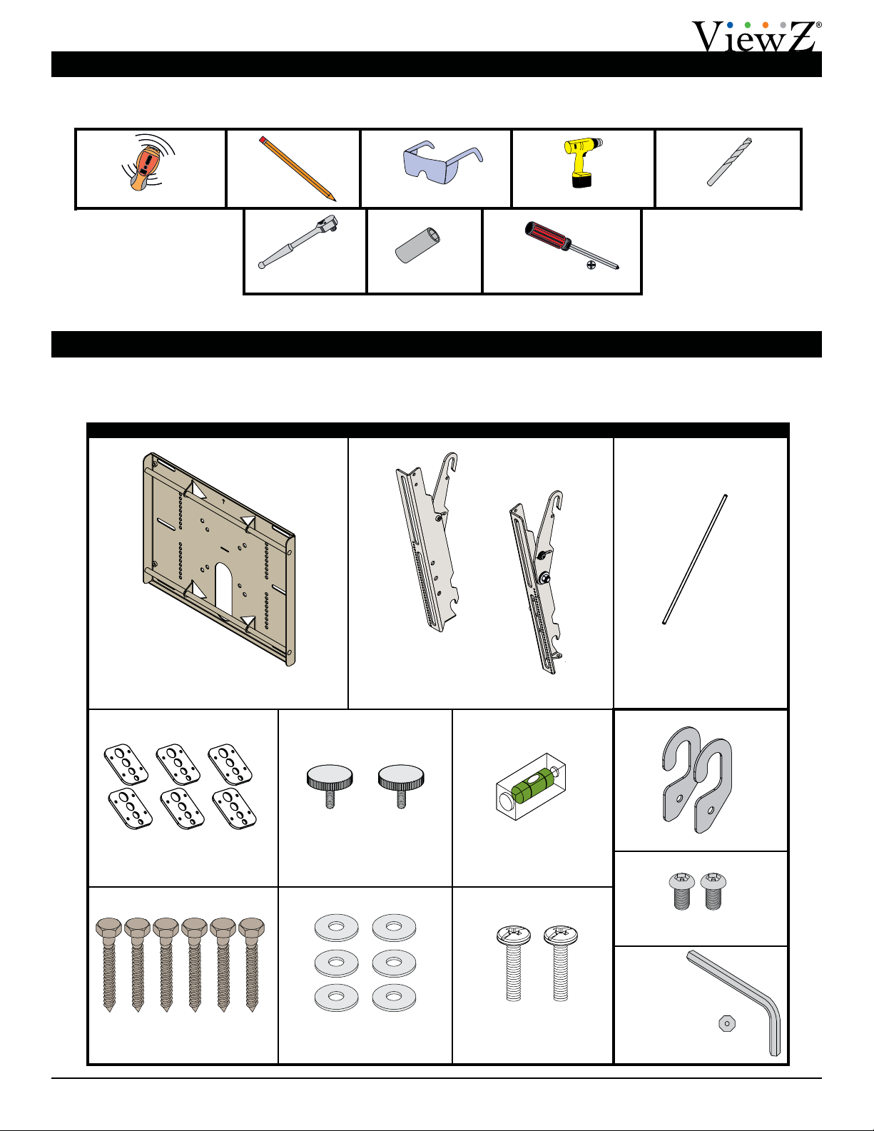
Parts List
Installation Tools
The following tools may be required, dependent upon your particular installation. These tools are not provided by
ViewZ, but you can purchase them at your local hardware store.
Your ViewZ product is shipped with all proper installation hardware and components. Make sure that none of these
parts are missing and/or damaged before beginning installation. If there are parts missing and/or damaged, please stop
the installation and contact Viewz at 1-888-99-ViewZ.
VZ-CMK03 Tilting Wall Mount Assembly Components
Wall Plate
(Qty 1)
Mounting Bracket
(Qty 2)
Griplate™ Washer
(Qty 6)
5/16˝ Flat Washer
(Qty 6)
Level
(Supplied)
Pencil Protective Eyewear
Phillips Head ScrewdriverSocket Wrench
Electronic Stud Finder ¼˝ Drill Bit
½˝ Socket
M6 Safety Knurl Knob
(Qty 2)
Thread Depth Indicator
(Supplied)
M6 x 30mm Locking Safety
Screw (Qty 2)
5/16˝ x 3˝ Lag Bolt
(Wooden Studs Only) (Qty 6)
Portable Drill
Panelock™ Hardware Kit
M6 x 12mm Security Head
Screw (Qty 2)
Panelock™ Hooks (Qty 2)
Security Head
Allen Wrench
VZ-CMK03
Page 4 Visit the ViewZ website at http://www.viewzusa.com Installation Instructions
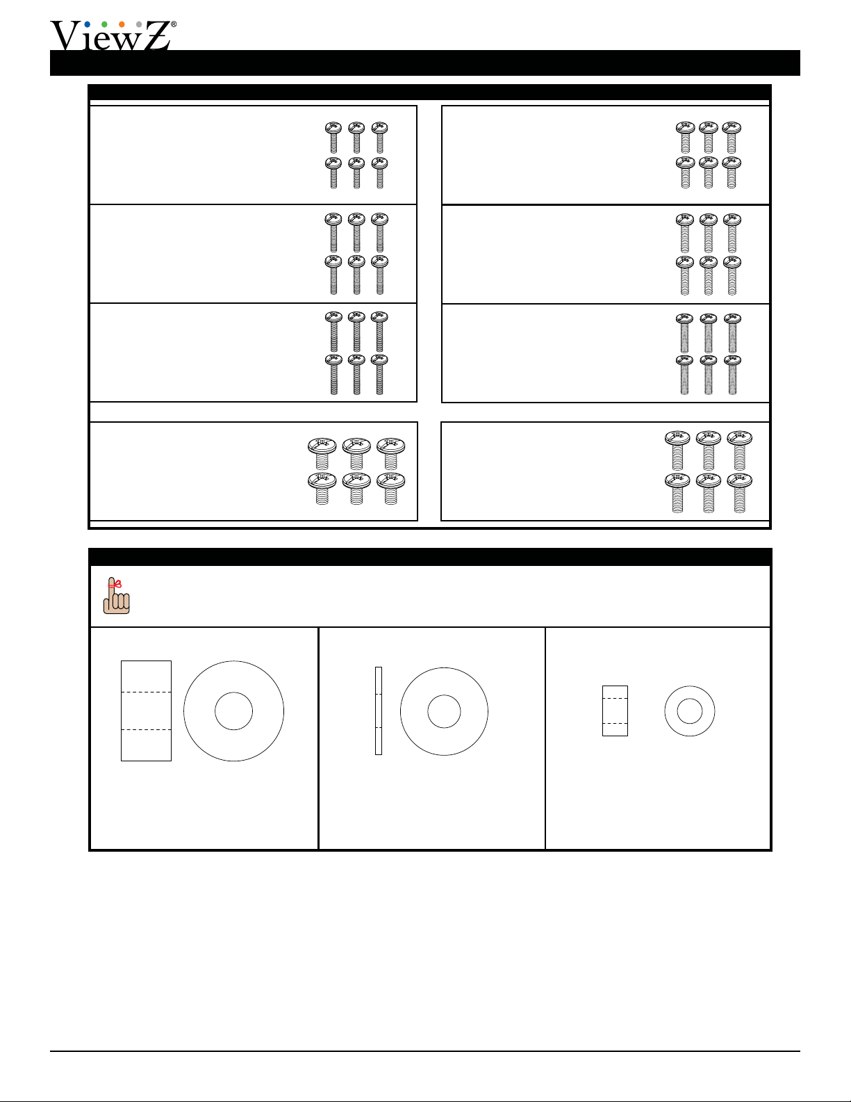
Mounting Hardware
Parts List (cont’d)
M4 x 25mm Combo Screw
(Qty 6)
M4 x 16mm Combo Screw
(Qty 6)
M4 x 20mm Combo Screw
(Qty 6)
M5 x 16mm Combo Screw
(Qty 6)
M5 x 20mm Combo Screw
(Qty 6)
M5 x 25mm Combo Screw
(Qty 6)
M6 x 12mm Combo Screw
(Qty 6)
M6 x 20mm Combo Screw
(Qty 6)
Nylon Spacers and Flat Washers
You may stack the nylon spacers to achieve proper spacing.
½˝ Nylon Spacer (Large)
(Qty 6)
5/16˝ Flat Washer (Metal)
(Qty 6)
¼˝ Nylon Spacer (Small)
(Qty 6)
VZ-CMK03
Installation Instructions Visit the ViewZ website at http://www.viewzusa.com Page 5
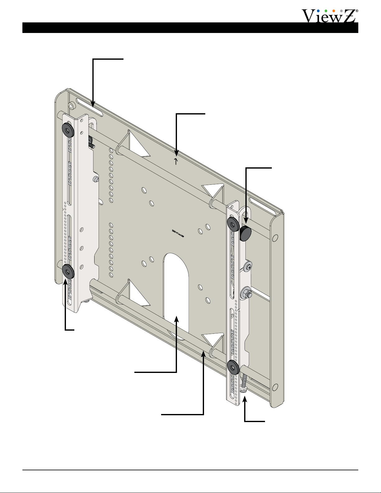
Features
Safety Knurl Knobs
Prevent the at panel from
being removed or dislodged
from the wall plate.
Locking Safety Screws
Prevent the at panel from
being removed or dislodged
from the wall plate.
Directional Mounting Arrow
Lets you know which edge is the top.
Cable/Electrical Cut Out
Allows for easy cable
access and power
distribution installations.
Mounting Slots
Allow for a variety of stud
congurations and
lateral adjustments when
installing the wall plate.
Nylon Spacers
Provided in various
sizes to accommodate
multiple screw sizes.
Mounting Rails
Allow lateral adjustments
when mounting the at panel.
VZ-CMK03
Page 6 Visit the ViewZ website at http://www.viewzusa.com Installation Instructions
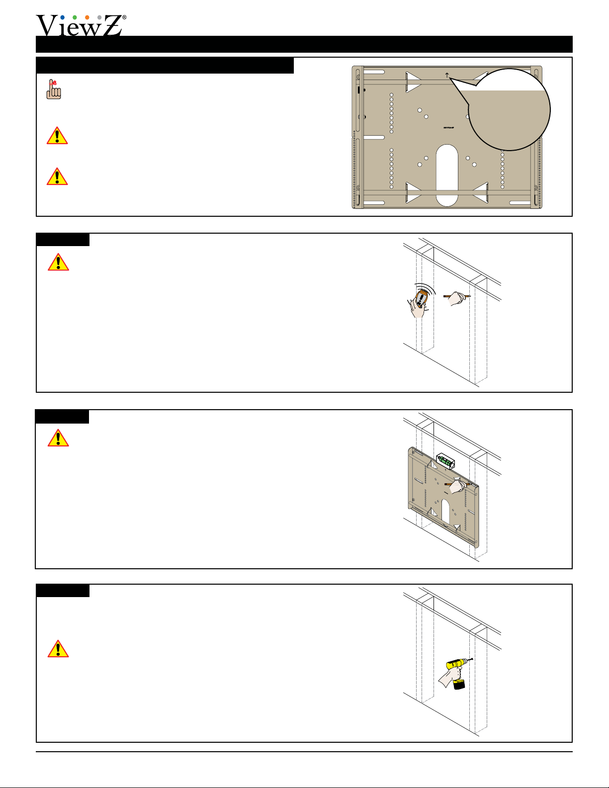
Installing the Wall Plate
Introduction
Directional Mounting Arrow
The Directional Mounting Arrow stamped into the
VZ-CMK03 wall plate indicates which edge is the
top.
Mounting Safety
Two people are recommended to install the wall
plate.
You must secure the wall plate to two (2) wall
studs with six (6) lag bolts (3 lag bolts for each
stud found).
You must secure the wall plate to two (2) wall
studs with six (6) lag bolts (3 lag bolts for each
stud found).
1) Use a stud nder to determine the exact center of
wall studs in the vicinity of the wall plate.
2) Use a pencil to mark the exact center of each of the
wall studs.
Step 1
Step 2
Step 3
Two people are recommended for this step; one
person to level the wall plate and another person
to mark the wall stud location.
1) Place the wall plate against the wall in the desired
viewing location.
2) Adjust the wall plate to align the mount slots in the
wall plate with the center of the wall studs.
3) Level the wall plate.
4) Use a pencil to mark the upper right mounting
location along the center of the wall stud.
Drill a “pilot hole” in the center of the upper right mark
using a ¼″ drill bit and power drill.
Only use a ¼˝ drill bit when drilling pilot holes.
XX
XX
XX
VZ-CMK03
Installation Instructions Visit the ViewZ website at http://www.viewzusa.com Page 7
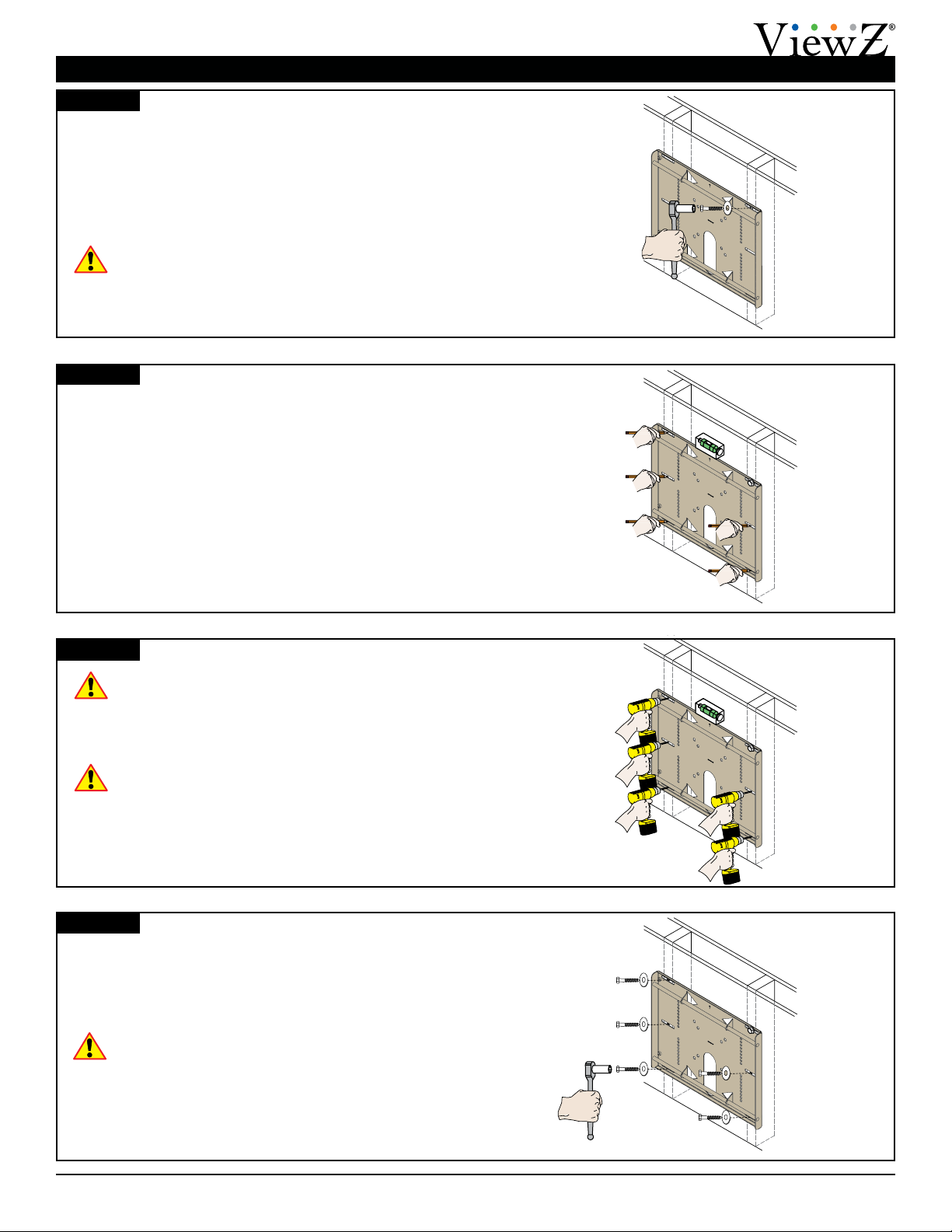
Installing the Wall Plate (cont’d)
1) Place the wall plate against the wall and align it with
the pilot hole.
2) Insert one (1) 5/16˝ x 3˝ lag bolt and one (1) 5/16˝
washer into the upper right pilot hole.
3) Use a socket wrench and a ½˝ socket to tighten the
lag bolt.
Do not overtighten the lag bolt.
Step 4
Step 5
Step 6
1) Level the wall plate.
2) Use a pencil to mark the remaining ve (5) mounting
locations along the center of each wall stud.
Two people are recommended for this step; one
person to level the wall plate and another person
to drill the pilot holes.
Drill a “pilot hole” in the center of each of the marks with
a power drill and a ¼″ drill bit.
Only use ¼″ drill bit when drilling the pilot holes.
Step 7
1) Insert one (1) 5/16″ x 3″ lag bolt and one (1) 5/16″
washer into each pilot hole
2) Tighten all lag bolts using a socket wrench and ½″
socket.
Do not overtighten the lag bolts when attaching
the mount to the wall. Improper installation may
result in personal injury or property damage.
Proceed to the “Installing the Mounting Bracket” on
page 8.
XX
XX
XX
XX
VZ-CMK03
Page 8 Visit the ViewZ website at http://www.viewzusa.com Installation Instructions
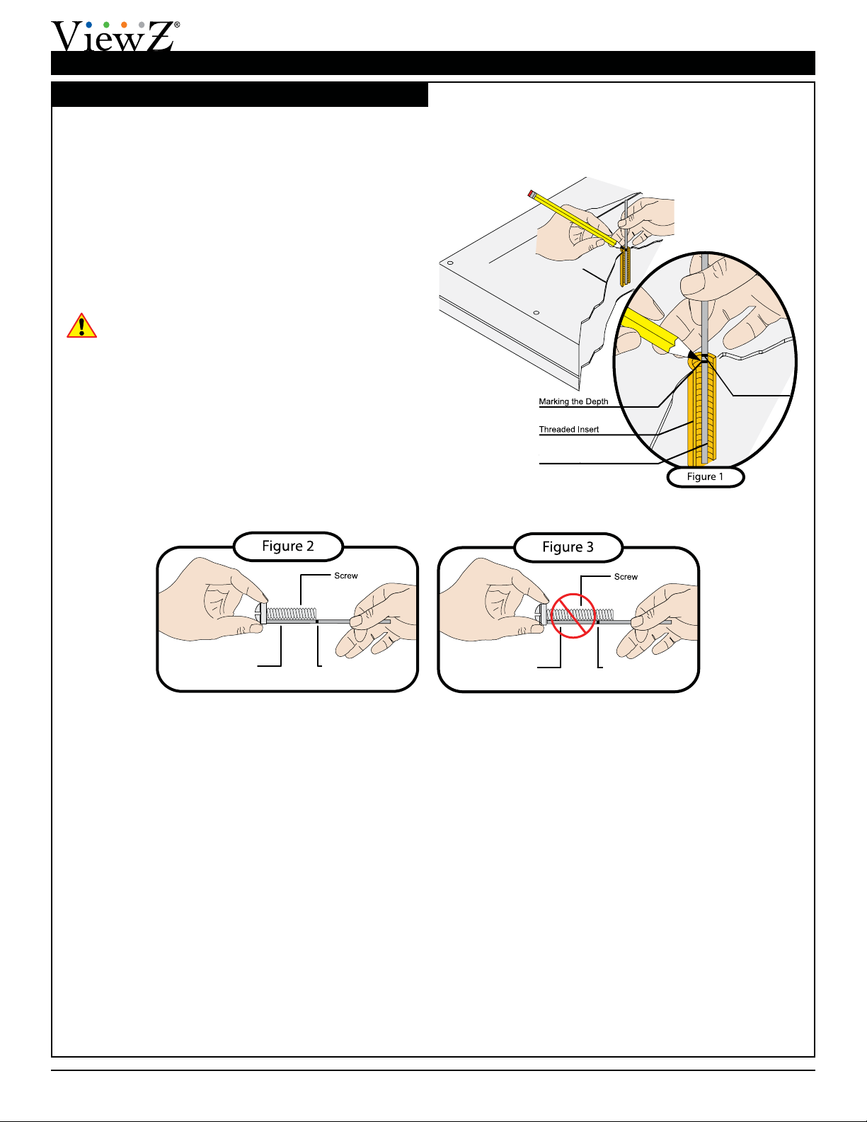
Installing the Mounting Brackets
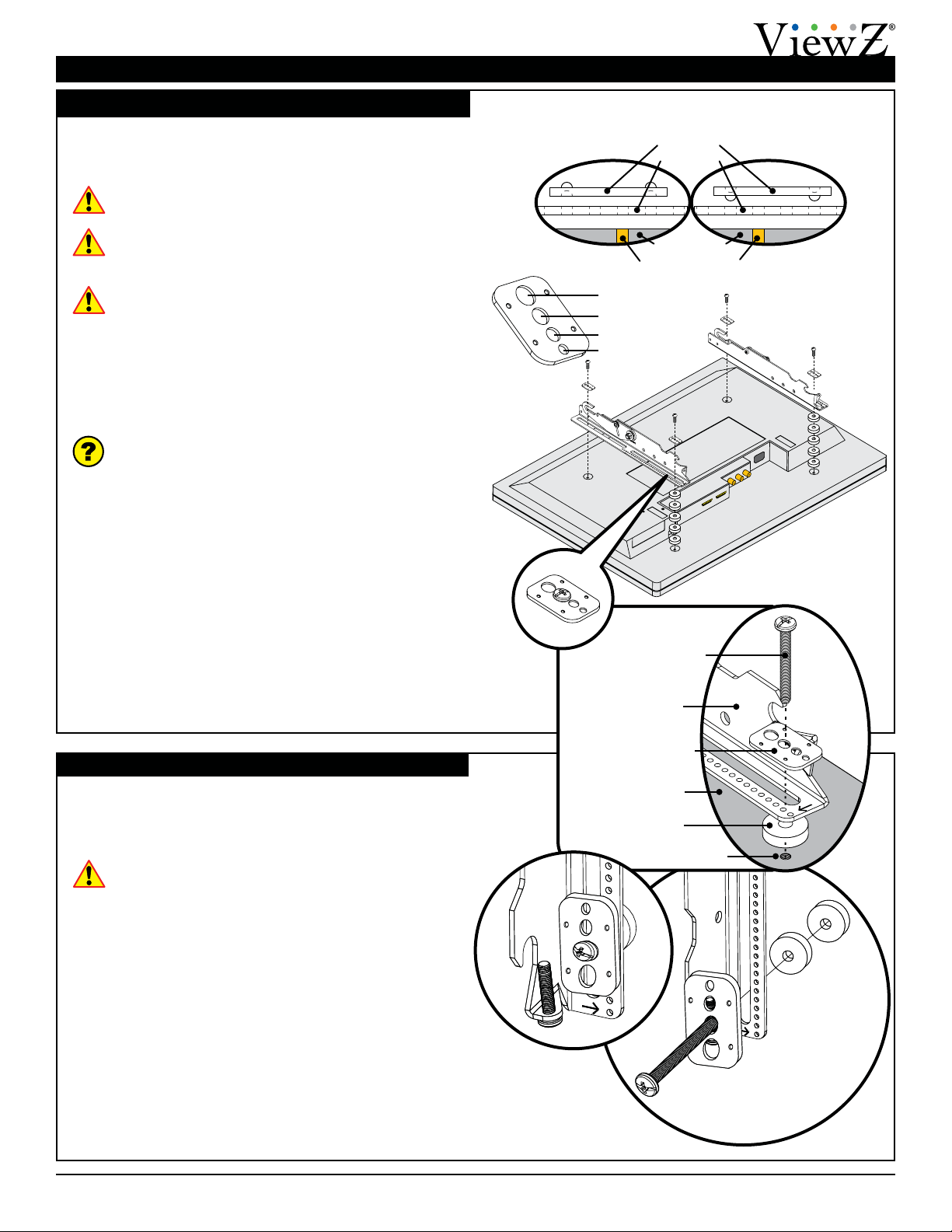
Selecting the Mounting Hardware
1) Insert a small straw or toothpick into the threaded
inserts found on the back of the at panel.
2) Use a pencil to mark the depth of the threaded
insert on the small straw or toothpick.
3) Mark the straw or toothpick 1/8” above the depth of
the threaded insert, as shown in Figure 1.
4) Insert the small straw or toothpick into the remaining
threaded inserts to compare and verify their depth
using the straw or toothpick’s 1/8” allowance mark.
5) Locate the correct diameter screw for the threaded
insert.
If the screw you selected is longer than the 1/8”
allowance mark on the small straw or toothpick,
as shown in Figure 2 and Figure 3, do not use
this screw. The screw length must not bypass the
mark.
6) Test each size of the screws provided.
The correct screws should thread easily into the
mounting point and not pull out when tension is
applied.
Go to “Griplate™ Washer Installation” on page
9.
Small Straw or Toothpick
Marking the 1/8”
Allowance
Small Straw
or Toothpick
Small Straw
or Toothpick Depth Plus 1/8” Allowance
Mark
Depth Plus 1/8” Allowance
Mark
VZ-CMK03
Installation Instructions Visit the ViewZ website at http://www.viewzusa.com Page 9
Installing the Mounting Brackets (cont’d)
Flat Panel
Griplate™Washer
Nylon Spacer
Mounting Bracket
Mounting Point
Mounting Screw
Griplate™ Washer Installation
ViewZ’s Griplate™ washers are designed to
accommodate M4, M5, M6 and M8 hole sizes required by
at panels.
Do not place excessive pressure on the back of the
at panel, as this may damage the at panel.
The Griplate™ washers must be installed between
the head of the mounting screw and the mounting
bracket as shown.
The dimples on the Griplate™ washers must be
oriented as follows:
●The Griplate™ washers installed at the top
of the at panel must have the points of the
dimples facing away from the at panel.
●The Griplate™ washers installed at the bottom
of the at panel must have the points of the
dimples facing towards the at panel.
Does the at panel have:
●Recessed mounting points?
●Uneven mounting points?
●A curved back?
●Any obstruction near the mounting point?
If Yes, you must install nylon spacers. Proceed to
“Nylon Spacer Installation” below.
If No, you do not need nylon spacers. Proceed to
“Attaching the Mounting Brackets to the Flat Panel”
on page 10.
Nylon Spacer Installation
ViewZ’s nylon spacers allow you to attach the mounting
bracket to at panels which have recessed or uneven
mounting points. Each nylon spacer will add distance
between the mounting bracket and the at panel.
The nylon spacers must only be installed between
the mounting bracket and the at panel.
The nylon spacers will t M4, M5, M6 and M8 screw
sizes.
M8
M6
M5
M4
Griplate™
Washer
Flat Panel
Mounting Point
Bracket
Top
Griplate™ Washer
Dimple Orientation
Bottom
Griplate™ Washer
Dimple Orientation
VZ-CMK03
Page 10 Visit the ViewZ website at http://www.viewzusa.com Installation Instructions
Installing the Mounting Brackets (cont’d)
This section presumes that you have read and
understood these sections:
●Selecting the Proper Mounting Hardware
●Universal Washer Installation
●Universal Spacer Installation
1) Place your at panel screen-side down on a soft, at
surface.
2) Identify the number and location of the thread
inserts on the back of your at panel.
3) Aligning the holes on each mounting bracket with
the thread inserts on the back of your at panel.
4) Secure each mounting bracket to your at panel by
inserting a minimum of two (2) screws per bracket.
Do not overtighten the mounting hardware.
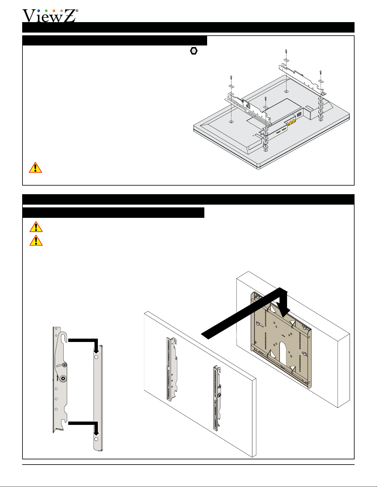
Attaching the Mounting Brackets to the Flat Panel
Attaching the Flat Panel to the Wall Plate
Mounting the Flat Panel
This section requires two people.
Do not release your at panel until you are certain
that top and bottom hooks of both mounting
brackets are securely seated on the upper and
lower mounting rails of the wall panel.
1) Raise the at panel past the top and bottom
mounting rails on the wall panel.
2) Slide the at panel down slowly, keeping it close to
the wall.
3) Engage the top and bottom mounting brackets to
the rails of the wall plate.
Proceed to “Mounting the Flat Panel” below.
Indice
Altri manuali ViewZ Rack e supporto

ViewZ
ViewZ VZ-RCR Series Manuale utente

ViewZ
ViewZ VZ-FSM2x2 Manuale utente

ViewZ
ViewZ VZ-CMK01 Manuale utente

ViewZ
ViewZ VZ-RMK08 Manuale utente

ViewZ
ViewZ VZ-SM01 Manuale utente

ViewZ
ViewZ VZ-AM03 Manuale utente

ViewZ
ViewZ VZ-CMK04 Manuale utente

ViewZ
ViewZ VZ-FSM3x2 Manuale utente

ViewZ
ViewZ VZ-XMS-SP49 Manuale utente


