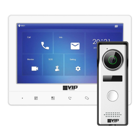
Vip-Vision INTIPMONBLW Manuale utente

VIP Residential IP Intercom Installation Guide - Issued January 2017 1
VIP Residential IP Intercom
Installation Guide

VIP Residential IP Intercom Installation Guide v1.1 - Issued January 2017
2
Table of Contents
1 Pre-Installation 3
1.1 Installation Requirements & Notes 3
1.2 Components 4
2 Installation 8
2.1 1 Indoor Monitor Door Station (No Network Functionality) 8
2.2 1 Indoor Monitor to 1 Door Station via a Network Switch 9
2.3 2 Indoor Monitors to 1 Door Station via a Network Switch 11
2.4 2 Indoor Monitors to 2 Door Stations via a Network Switch 14
3 Additional Configuration 19
3.1 How to change the Indoor Monitor's IP Address 19
3.2 How to set up an Indoor Monitor as an Extension Monitor 19
3.3 How to change the Door Station's IP Address 20
3.4 Setting the Time and Date 23
3.5 Wiring an Electric Door Strike to the Door Station 24
3.6 Adjust Electric Door Strike Timing 25
3.7 Learning in Swipe Cards 25
3.8 Deleting Swipe Cards 26
3.9 Indoor Monitor Volume Configuration 26
3.10 Door Station Volume Configuration 26
3.11 P2P Configuration (QR Code) 27
3.12 Advanced Configuration for Remote Access (optional) 29
3.13 Changing Door Station Network Ports (optional) 29
3.14 Finding out your network range, and available IP addresses via PC 30
3.15 Using the INTIPMONPOE (Sold Separately) 31
3.16 Using a PoE Switch to Power the Intercom System (Sold Separately) 31
3.17 Adding IP Cameras to an Indoor Monitor 32
3.18 Adding Your Door Station to a VIP Vision NVR 33
4 How to Use Your Intercom System 34
4.1 Making and Answering Calls 34
4.2 Taking Videos / Snapshots from the Indoor Monitor 34
4.3 Viewing Your Videos/Snapshots from the Indoor Monitor 34
4.4 Calling Between Indoor Monitors 35
4.5 Create Favourites 35
5 Updating Intercom Firmware 36
6 Troubleshooting 38
7 Limited Warranty 39

VIP Residential IP Intercom Installation Guide - Issued January 2017 3
1 Pre-Installation
1.1 Installation Requirements & Notes
1.1.1 Door Station Web Interface Login
To access the door station's Web Interface, you will need a Windows computer (in the same IP address range)
that can connect to the Internet.
A maximum of 6 Indoor Stations and 6 Door Stations can be connected.
The User Password is 123456 which may be used for basic operation of the Intercom System.
The Project Settings Password is 888888 which may be used for configuration of the Intercom System.
The Door Station’s web interface will require the default username admin and password admin.
The Door Station’s default IP address is 192.168.1.110
The Indoor Monitors default IP address is 192.168.1.109
Please note that only the Door Station has a web interface; the Indoor Monitor does not.
1. Open Internet Explorer and input the Door Station
IP Address in to the address bar.
e.g. http://192.168.1.110
(Refer to Section 3.1 for how to change the door
station's IP address.)
2. Log in with the default username admin, password
also admin.

VIP Residential IP Intercom Installation Guide v1.1 - Issued January 2017
4
VIP Residential IP Intercom Indoor Monitor
Product ID — INTIPMONBLW (white), INTIPMONBL (black)
• Advanced H.264 Video Compression Technology for High Quality Images
• 800 x 480 pixels resolution
• 7”Touch Screen
• Built in 4GB MicroSD Card (non-removable)
VIP Residential IP Intercom Door Station
Product ID — INTIPRDSVW
• 1MP Camera
• IP54 Rated
• Loudspeaker
• Door Release Output
VIP Residential IP Intercom Door Station
Product ID — INTIPRDSBW (white), INTIPRDSB (black)
• 1MP Camera
• Built-in NFC Card Reader
• Weather Resistant Front Panel (Sheltered Installation recommended)
• Loudspeaker
• Door Release Output
1.2 Components

VIP Residential IP Intercom Installation Guide - Issued January 2017 5
1
2
1When lit, the LED indicates that there is a missed call,
or a message has been left.
2When lit, the LED Indicates that the Indoor Monitor is
powered on
Press to view the Door Station’s camera
Press to view the Door Station’s camera
Press to answer the call, once finished, press to hang-
up the call.
Press to return to the main menu
Not Used
INTIPMONBL(W) - Front
INTIPMONBL(W) - Back
1
2
3
4
1Alarm Inputs Insert a small screwdriver, and gently move the
camera to the desired position.
2RJ-45 Port To connect a Cat5 cable.
3Power Input To connect 12V DC.
4Debug Port Not used.

VIP Residential IP Intercom Installation Guide v1.1 - Issued January 2017
6
1Camera Adjustment Insert a small screwdriver, and gently move the
camera to the desired position
2Tamper Switch This must be fully pressed down once installed. If
the switch is released, the alarm will sound.
3RJ-45 Port To connect a Cat5 cable, with the included adaptor
4Debug Port Not used.
5Input Connectors Connections for 12V DC, and Door Strike wiring
1Microphone
2Camera
3Compensation Light
4Speaker
5Name Plate
6Call Button
1
2
3
4
5
6
1
2
3
4
5
INTIPRDSVW - Front
INTIPRDSVW - Back

VIP Residential IP Intercom Installation Guide - Issued January 2017 7
1Tamper Switch This must be fully pressed down once installed. If
the switch is released, the alarm will sound.
2RJ-45 Port To connect a Cat5 cable.
3Power Input 12V DC Input
4Connection Port Door Station wiring is to be connected to these
ports, with the included breakout cable
5Speaker Speaker
1Compensation Light
2Camera
3NFC Card Reader
4Call Button
1
2
3
4
5
1
2
3
4
INTIPRDSB(W) - Front
INTIPRDSB(W) - Back

VIP Residential IP Intercom Installation Guide v1.1 - Issued January 2017
8
If this is your first time purchasing a VIP Residential IP Intercom, we recommend setting it up on the bench be-
fore installation, to familiarize yourself with the product.
If you are setting up more than one Door Station, or wish to connect to the Door Stations web interface, a Win-
dows computer is required to login to the Door Station.
The IP intercom requires a Cat5 cable to be run between the Indoor Monitor, and Door Station. If you wish to
connect to the system remotely your Monitor and Door Station must be connected to your modem or network
switch (sold separately). 12V DC power must be provided to each Door Station and Indoor Monitor.
When connecting to the Door Stations’ web interface, the default IP address is 192.168.1.110. We recommend
using Internet Explorer to connect to the Door Station. Please note that the Indoor Monitor does not have a web
interface.
This configuration requires a length of Cat5 cable running between the Indoor Monitor, and Door Station.
12VDC power must be provided to both the Door Station, and Indoor Monitor
1. Install each unit at their respective location and connect the devices together with a Cat5 cable.
2. Power both the Indoor Monitor and Door station with 12VDC.
3. You have now successfully connected your VIP Residential IP Intercom.
2 Installation
2.1 1 Indoor Monitor Door Station (No Network Functionality)
+ / -
12VDC
+ / -
12VDC
Power
Cat5e
Indoor MonitorDoor Station

VIP Residential IP Intercom Installation Guide - Issued January 2017 9
This configuration allows you to connect your Indoor Monitor and Door Station together, and provide them
with network access.
Cat5 cable will need to be run between the Indoor Monitor, Door Station, and Network Switch
(sold separately). 12V DC power must be provided to both the Door Station, and Indoor Monitor.
A Cat5 cable will need to be connected from the Network Switch to your existing computer network.
In this example, we are going to connect the intercom Door Station and Indoor Monitor to a Network Switch,
and change the IP address of the Door Station and Indoor Monitor.
Device IP Adresses Subnet Mask Gateway Room Number
Door Station 10.1.1.110 155.155.155.0 10.1.1.1
Master Indoor
Monitor
10.1.1.111 255.255.255.0 10.1.1.1 9901
1. Install each unit at their respective location and both the Indoor Monitor and Door Station with a Cat5 cable,
to the Network Switch.
2. Connect a Cat5 cable from the Network Switch, to your existing computer network.
3. Connect a 12VDC power supply to both the Door Station, and Indoor Monitor.
4. Once the Indoor Monitor has powered on, go to“Settings”>“Project Settings”> then enter password 888888.
Settings”> then enter the password 888888.
Switch
Indoor MonitorDoor Station
2.2 1 Indoor Monitor to 1 Door Station via a Network Switch
+ / -
12VDC
+ / -
12VDC
Power
Cat5e
5. Choose“Net Set”and change the IP address,
subnet mask, and default gateway to
match your local computer network. Press
“OK” to save. In this example, we are going
to change the IP address of the Indoor
Monitor from 192.168.1.109 to 10.1.1.111.

VIP Residential IP Intercom Installation Guide v1.1 - Issued January 2017
10
6. On the Indoor Monitor go to “Settings” >
“Project Settings”> then enter the password
888888.
7. Select “Search Device”. You will see the Door
Station’s IP address listed.
8. Select the Door Station, then select “Modify
IP” and change the IP address, subnet mask
and default gateway of this Door Station
from 192.168.1.110 to the new IP address
10.1.1.110 Press “OK” to save.
9. Once you have set the Door Stations IP
address, select the Door Station, then the
“Add” button.
10. Enter a name for the Door Station for
example “Front Gate”. Press the “OK” button.
11. A green icon will now appear next to the
IP address indicating the Door Station is
connected.
12. Turn off power to both the Door Station and
Indoor Monitor, after 10 seconds, turn the
power back on.
13. You have now successfully connected your
VIP Residential IP Intercom.
Questo manuale è adatto per i seguenti modelli
2
Indice
Altri manuali Vip-Vision Sistema di interfono