VISCOR ALRA-ALRB-C91 Manuale utente

1
ALRA-ALRB-C91
Installation Instructions
ERP: IIS00271
NOTES
Installation should be completed by an individual familiar with the construction and operation of the luminaire.
Installation of luminaire must be in accordance with national and local building and electrical codes.
Carefully read and follow all warnings and instructions before installing or servicing the luminaire.
Instructions do not cover all details and all possible product configurations.
Do not restrict luminaire ventilation.
Ensure LED luminaire is not covered with material that will prevent convection or conduction cooling.
Do not exceed luminaire’s maximum ambient temperature.
Ensure LED luminaire has the correct polarity before installation.
These products have maximum rated output voltage that exceeds the voltage limits that cannot be accessible based on voltage restrictions for
Class 2 circuits in Canadian Electrical Code. This output complies with the definition of Class 2 per Canadian Electrical Code. This product com-
plies with this requirement since the installation instruction requires installation in restricted access area.
Do not mount the luminaire to ceiling if convenience outlet option is provided.
Do not use the luminaire housing as junction box cover unless the housing width is wider than the junction box.
WARNINGS
Electric shock:
Disconnect or turn off power before installing or servicing luminaire.
All electrical wiring to be completed by a qualified licensed electrician
in accordance with local and National/Canadian Electrical Code.
Ensure supply voltage corresponds with the correct ballast/driver
voltage.
Avoid exposing wiring to metal edges and sharp objects.
Ensure that the luminaire is properly grounded to prevent electric
hazards.
Fire:
Keep flammable and combustible materials away from the light source
and/or lens.
Use correctly rated supply conductors as indicated by product label-
ing.
Burn:
Allow luminaire to cool before handling luminaire.
Personal Injury:
Wear safety glasses and gloves when handling the luminaire to avoid
physical injury.
Avoid direct eye contact with light source.
Always support the weight of the luminaire.
Viscor is not responsible for any injuries due to the improper installation or handling of its products.
01/21/2020-Rev1.0
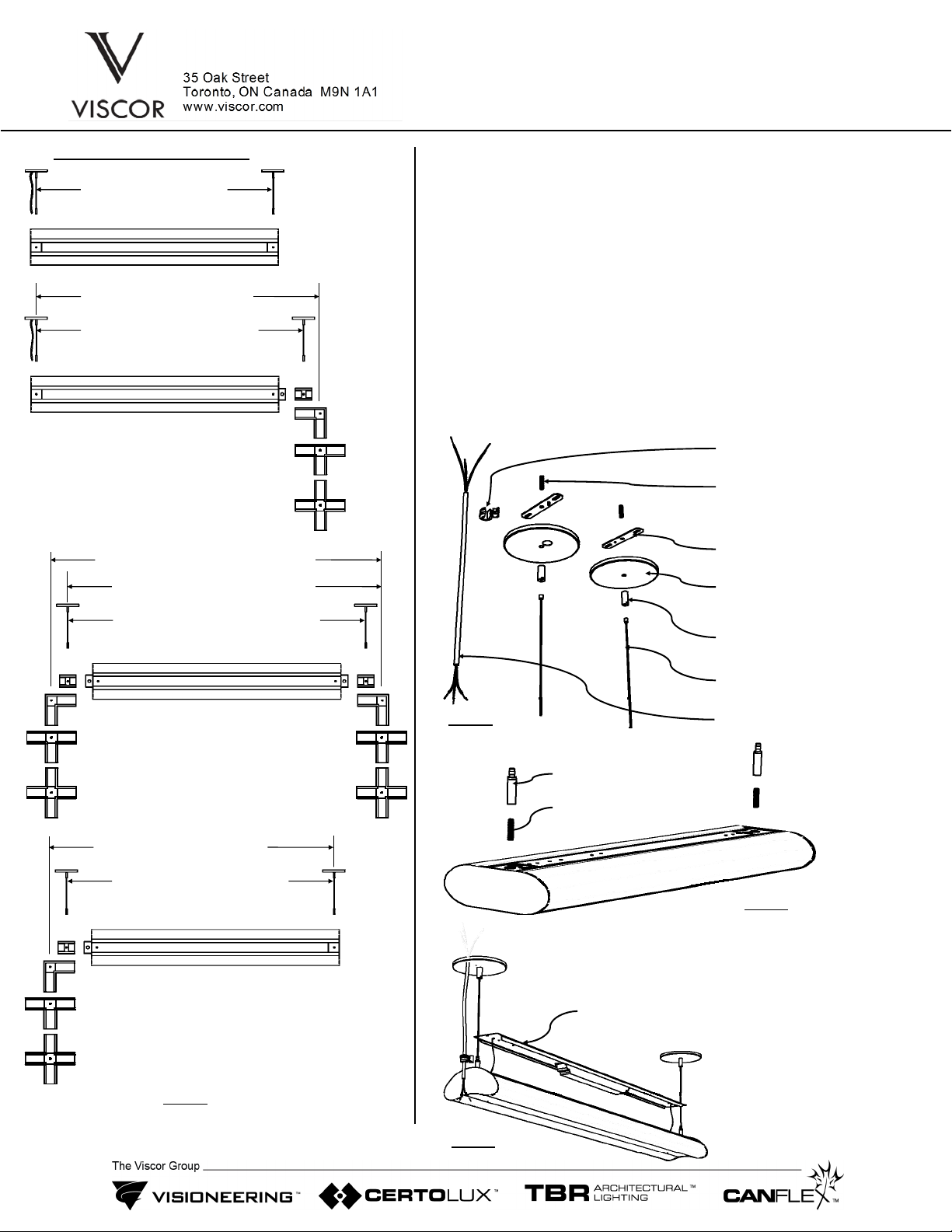
C91 - Stand alone unit with two flat finished ends. (power feed, canopies & aircraft cables included)
M56 - Start unit of configurable lighting system with one flat finished end and one open end.
M57 - Middle unit of configurable lighting system with two open ends.
M58 - End unit of configurable lighting system with one flat finished end and one open end.
S-connector L-connector T-connector X-connector
Fixture/Housing Construction
Configurable Lighting System Connectors
2
Step 1. Using canopy spacing information provided (dwg 1) create
canopy layout.
Step 2. Disconnect power.
Step 3. Install canopy sets (dwg 2) (cross bars, threaded rods,
canopies, cable couplers, AC cables, power cords) and
connect power cord /cords . For canopy spacing refer to
layout.
Step 4. Stand alone unit installation (C91): Install cable grippers via
1/4-20 threaded rods (supplied) to the fixture (dwg 3) and hang
the fixture inserting AC cables through cable grippers. Adjust
suspension height as required and level the fixture. Remove
fixture cover (dwg 4) and connect power to the fixture utilizing
strain relief (provided) and make wiring connections according
to local electrical codes. Reinstall cover.
INSTRUCTIONS:
ALRA-ALRB-C91
Installation Instructions
ERP: IIS00271 01/21/2020-Rev1.0
(4ft/8ft nom.) - 43” / 87”
C91
(4ft/8ft nom.) - 45.5” / 89.5”
M56
(4ft/8ft nom.) - 48.5” / 92.5”
(4ft/8ft nom.) - 48” / 92”
M57
(4ft/8ft nom.) - 51” / 95”
(4ft/8ft nom.) - 54” / 98”
(4ft/8ft nom.) - 45.5” / 89.5”
M58
(4ft/8ft nom.) - 48.5” / 92.5”
Canopy Spacing Information
Dwg 1
AC cable
Canopy
Threaded rod
Cable coupler
Strain relief
Cross bar
Power cord
Dwg 2
Threaded rod
Dwg 3
Cable Gripper
Dwg 4
Fixture Cover
3
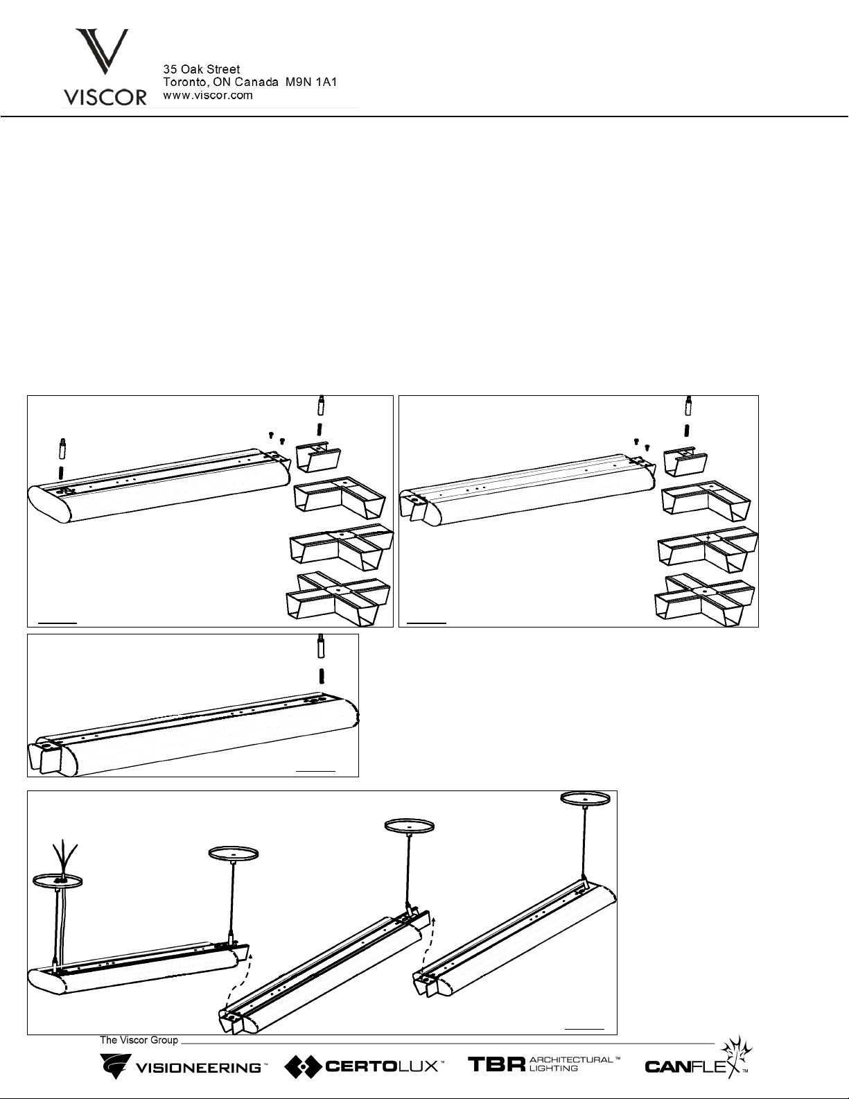
Step 4. Configurable Lighting System installation:
- Lay on the floor units and connectors in required order.
- Attach required connector (S,L,T or X) to unit M56, secure it via 2 screws and install cable grippers (2x) via 1/4-20
threaded rods (dwg 5).
- Attach required connector (S,L,T or X) to each M57 unit, secure it via 2 screws and install cable gripper via 1/4-20 threaded
rod to the connector (dwg 6).
- Install cable gripper via 1/4-20 threaded rod to unit M58 (dwg 7).
- Hang unit M56 (dwg 8) inserting AC cables through cable grippers. Adjust suspension height as required and level the unit.
- Hang the next unit and attach the loose end to previously mounted unit, secure it via 2 screws and level it. Repeat steps
until configurable lighting system installation is complete by hanging unit M58.
Step 5. Remove fixture cover (dwg 4) and connect power to the first unit utilizing strain relief (provided) and make wiring
connections to the remaining units according to local electrical codes. Reinstall covers.
Step 6. Connect the power.
INSTRUCTIONS (Cont’d):
ALRA-ALRB-C91
Installation Instructions
ERP: IIS00271 01/21/2020-Rev1.0
Dwg 5
M56 M57
Dwg 6
Dwg 7
‘S’
‘L’
‘T’
‘X’
‘S’
‘L’
‘T’
‘X’
M57
M56 M58
Dwg 8
M58
Altri manuali VISCOR Lanterna


