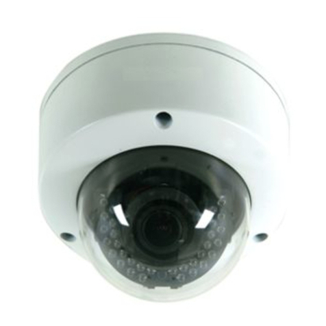
VISUALINT VI-3100 Manuale utente

VI-3100
Installation Guide

INFORMATIONTOUSER
CAUTION
RISKOFELECTRICSHOCK,
DONOTOPEN
CAUTION:TOREDUCETHERISKOFELECTRICSHOCK,
DONOTREMOVECOVER(ORBACK).
NOUSERSERVICEABLEPARTSINSIDE.
REFERSERVICINGTOQUALIFIEDSEERIVCEPERSONEL.
This symbol is intended to alert the user to the presence of uninsulated
“dangerousvoltage”withintheproduct’senclosurethatmaybeofsufficient
magnitudetoconstituteariskofelectricshocktopersons.
This symbol is intended to alert the user to the presence of important
operatingand maintenance (servicing) instructions in the literature
accompanyingtheappliance.
!
!

VI3100 InstallationGuide
01A.05 3
Table of Contents
1.FEATURES..............................................................................................................4
2.PACKAGECONTENTS..............................................................................................5
3.PARTNAMES.........................................................................................................6
4.INSTALLATION.......................................................................................................8
4.1.InstallationTemplate.........................................................................................................9
4.2.AdjustingLEDoptionsandlensfocus..............................................................................10
4.3.SettingtheImageAttribute.............................................................................................10
5.CABLECONNECTIONS...........................................................................................11
6.CONFIGURATION.................................................................................................13
6.1.Setupnetworkenvironment...........................................................................................13
6.1.1.GenericIPEnvironment............................................................................................13
6.1.2.CustomIPEnvironment............................................................................................14
6.2.Viewvideoonwebpage..................................................................................................15
6.2.1.AccessthroughIPAdminTool...................................................................................16
6.3.Reset................................................................................................................................17
6.4.FactoryDefault.................................................................................................................17
APPENDIX(A):SPECIFICATIONS...............................................................................18
Summary.................................................................................................................................18
ElectricalCharacteristics.........................................................................................................19
EnvironmentCondition...........................................................................................................19
EnvironmentCondition...........................................................................................................19
APPENDIX(B):DIMENSIONS....................................................................................20
APPENDIX(C):HEXADECIMALDECIMALCONVERSIONTABLE..................................21
REVISIONHISTORY..................................................................................................22

VI3100 InstallationGuide
01A.05 4
1
1
.
.
F
F
E
E
A
A
T
T
U
U
R
R
E
E
S
S
Camera
•Indoor/OutdoorIRBulletIPCamera
•1/2.7”1080pCMOS
•ICRtypetrueday&night
•ONVIFSupport
Streaming
•Dualstreamingmode(suchasdifferentcodec/resolution/bitrateandsoon.)
•Burntintextsupported
•Unicast/Multicastsupported
Video/Audio
•Videocompression:H.264/MJPEG,25/30FPS@1080p(PAL/NTSC)
•Analogvideooutforexternalmonitors
•VideoMotionDetectionsupported
Network
•RTSP/HTTPprotocolsupported
•10/100BaseTEthernet
AdditionalFeatures
•OSDforcameracontrolsupported
•VCApresence

VI3100 InstallationGuide
01A.05 5
2
2
.
.
P
P
A
A
C
C
K
K
A
A
G
G
E
E
C
C
O
O
N
N
T
T
E
E
N
N
T
T
S
S
Unpackcarefullyandhandletheequipmentwithcare.Thepackagingcontains:
Camera
Videooutcable
Hexwrenchdriver
Screws
QuickinstallationGuide
DCpoweradaptor
Screwanchors
Terminalblock
Theabovecontentsaresubjecttochangewithoutpriornotice.
Note
i

VI3100 InstallationGuide
01A.05 6
3
3
.
.
P
P
A
A
R
R
T
T
N
N
A
A
M
M
E
E
S
S
①Sunshield
Positionthesunshieldtopreventdirectsunshine.
②Controlpanel
OpenthecontrolpaneltocontrolLEDs,OSDmenus,extravideooutput,andresetbutton.
Tolearnhowtoresetyourdevice,referto6.3.Reset.
③Ventilationhole
Theventilationholeshelptoreducethetemperaturedifferencebetweeninsideandoutside
andpreventwaterfrombeingcondensate.
④Jointfor3axis
Usethisparttoadjustthecameratothedesiredposition.Referto4. Installationformore
details.
⑤Panningjoint
Usethispartforpanningadjustment.Referto4.Installationformoredetails.
⑥Tiltingadjustment
Usethispartfortiltingadjustment.Referto4.Installationformoredetails.
⑦4PinConnector
A:DO,B:DO+,C:DI+,D:DI
DCBA
C
D
*Modelshereinandtheirappearancearesubjecttochangewithoutanypriornotice.
①
④
⑦
⑥
⑤
②
�
�
�
�
�

VI3100 InstallationGuide
01A.05 7
⑧PowerAdaptorConnector
ThecameraneedsDC12Vforpowersupply.
⑨NetworkPort
UsethisRJ45LANconnectorforconnectingthecameratonetwork.
⑩AudioIn
Connecttotheaudioinputdevicesuchasamike.
⑪AudioOut
Connecttotheaudiooutputdevicesuchastheamplifierspeaker.
Thecontrolpanelalwaysshouldbefacingdowntothegroundwhenthecamera
hasbeeninstalled.Invertingthecamerabodywillcausemechanicalfailuredue
towaterorparticlespermeatingintoinvertedairventholesinopenarea.
Caution
!

VI3100 InstallationGuide
01A.05 8
4
4
.
.
I
I
N
N
S
S
T
T
A
A
L
L
L
L
A
A
T
T
I
I
O
O
N
N
Whileinstallingthecamera,donotinvertthecamerabodyinanycircumstances.
Thecamerafeaturesairventholesonthebottom
ofthedevice,andinvertingthe
camera position may cause water to permeate inside the device, resulting in
mechanicalfailures.
To prevent products from damaging, place the camera on stable and non
vibrating surfaces. Ifthe stabilityisin doubt,consult withsafetypersonnelfor
reinforcements,andthenproceedwiththeinstallation.
1)
Place theinstallationtemplatethatis providedin thepackage onthedesired
positionofinstallation.
2)Drillfourholesonthetemplateandinsertanchorblocksintotheholes.Fasten
thecamerawithscrews.
3)Makesurethecablesareproperlyconnectedtothecamera.
4)Adjustthecameratothedesiredanglebyunscrewthejointsbyreferringtothe
followingpictures.
Adjustthisjointto
installitonthewall
Tilingadjustment
Panningadjustment
Caution
!
Caution
!

VI3100 InstallationGuide
01A.05 9
4.1. Installation Template
(Unit:mm)

VI3100 InstallationGuide
01A.05 10
4.2. Adjusting LED options and lens focus
Adjustthezoomandfocusofthelenswiththeleverof①and②onthefollowingpicture.
TELE/WIDE:Usesforzoom
FAR/NEAR:Usesforfocus
AF:Autofocus
NT/PAL:NTSC,PALbutton
Vout:Usesonlyforinstallation
Do not invert the camera body to position the control panel on top of the
camera.
4.3. Setting the Image Attribute
Youcansettheimageattributeofcamerathroughthewebpage.
ThemenuofimageattributecanbeseenunderSetup>Video&Audio>Camera.Brightness,
contrast,saturationandsharpnesscanbeadjusted.
Note
i
TELE
WIDE NEAR
FAR AF
NT/PAL
RESET
VOUT
Indice
Altri manuali VISUALINT Telecamera di sicurezza