
Vmac VR7000 9037 Manuale utente

Installation Manual
For The
System #9037
UNDERHOOD AIR COMPRESSOR
1999-2000 FORD SUPER DUTY F250-F550
7.3 L POWER STROKE DIESEL
TEL: 250-754-6997
FAX: 250-754-6972
TOLL FREE: 800-738-8622
1333 KIPP ROAD, NANAIMO, B.C. V9X 1R3
DOCUMENT 19351

Installation Manual Document 19351
VR7000 Underhood Air Compressor
System Number 9037
Application: 1999-2000 Ford Super Duty F250-F550 7.3 L Power Stroke Diesel
Publication Date: September 1999
Origination Documents: #19351a - introduction
#19352 - compressor installation
#19353 - air tank and line installation
#19354 - control unit installation
#19355 - throttle commander installation
#19356 - illustrated parts list
#19130 - warranty registration
Notice:
Manuals and products are subject to change without notice.
Copyright 1999
The contents of this manual may not be reproduced in any form without the express written
permission of VMAC
Registered Trademarks:
VR7000, VMAC and Throttle Commander are registered trademarks of VMAC.
Ford, Super Duty, F250-F550, Power Stroke Diesel are registered trademarks of Ford Motor
Company
Loctite, Prime N’ Clean, 242 and PST are registered trademarks of Loctite Corporation.
Nylok is a registered trademark of Nylok Fastener Corporation.

General Information
System #9037
1999-2000 FORD
SUPER DUTY F250-F550
7.3 L POWER STROKE DIESEL
UNDERHOOD AIR COMPRESSOR
DOCUMENT 19351a

General Information
Introduction
This book provides installation instructions for:
VMAC underhood air compressor installation kit
VMAC Throttle Commander
This kit has been designed for:
1999-2000 Ford Super Duty F250 - F550 7.3 L Power Stroke Diesel
Installation steps
The installation procedure in this manual has four main steps:
Part 1: Installing the Compressor
Part 2: Installing the Regulator, Filter, Air Tank and Lines
Part 3: Installing the Control Unit
Part 4: Installing the Throttle Commander
Terms and symbols
This manual uses the following terms and symbols:
•OEM - Original Equipment Manufacturer
•HHCS - Hex Head Cap Screw (also called a hex bolt)
•SHCS - Socket Head Cap Screw (also called an Allen head bolt)
NOTE
WARNING
!
This symbol indicates that there is additional information or special emphasis
on a specific procedure.
This symbol indicates that there is a possibility of personal injury or damage to
the equipment if the indicated warning is not followed.
DOCUMENT 19351a

Installation Notes
1. It is important that you complete all the installation steps before operating the system.
Refer to the Owner’s Manual before operating the system for the first time.
2. Follow all safety precautions for underhood mechanical work.
3. Use Loctite 242 or equivalent on all engine-mounted fasteners.
4. All hoses, tubes and wires which are re-routed or shifted during installation must be
secured so that they do not contact excessively hot areas or sharp edges. Where
possible, follow the routing instructions in this manual.
5. These installation instructions are intended as a general guide. In some instances, due
to variations in vehicle manufacture (or if prior modifications have been made to the vehicle)
it may be necessary to carry out grinding, bending or rearranging operations for correct fit.
These operations must follow sound, standard shop practices.
6. Left and right definitions in this manual are determined when sitting in the driver’s
seat, facing forward.
7. All fasteners must be of the correct size and torqued according to the specifications
shown below. Torque specifications are in foot pounds (ft-lb).
8. The possibility exists that the primary installer may be color-blind. Always ensure
that another person confirms the color codes on the wires.
Type Grade 8 plated Class 10.9 unplated
Size In Cast or
Steel
In
Aluminum
In Cast or
Steel
In
Aluminum
3/8 48 45
7/16 77 70
1/2 117 95
M8 25 20
M10 45 40
M12 80 70
M14 145 130
DOCUMENT 19351a

Ordering Parts
To order parts, contact VMAC at:
Telephone 250-754-6997
Facsimile 250-754-6972
Office Hours 8:00 AM to 4:30 PM Pacific Time
Please quote the VMAC part number, the description and the quantity.
Warranty
The VMAC warranty form is located at the back of this manual. This warranty form must be
completed and mailed or faxed to VMAC at the time of installation for any subsequent warranty
claim to be considered valid.
The enclosed System Identification Number Plate (S/N) must be attached to the vehicle at the time
of installation.
Locate the S/N plate on the drivers side frame member in front of the battery. Drill the two hole
locations using a 7/64” drill bit. Place the S/N plate in position and fix in place with the two #6 pan
head self tapping screws provided.
IMPORTANT
This S/N plate provides information, which allows VMAC to assist in customer inquiries and/or
ordering of parts. It is important that this S/N plate is affixed to the vehicle.
DOCUMENT 19351a

Changes and improvements
These products and documents are subject to changes or improvements without notice.
DOCUMENT 19351a

Part 1
Installing
the Compressor and Oil
Cooler
System #9037
1999-2000 FORD
SUPER DUTY F250-F550
7.3 L POWER STROKE DIESEL
UNDERHOOD AIR COMPRESSOR
DOCUMENT 19352

Part 1: Installing the Compressor and Oil Cooler
1.1 Preparing for installation
1. Disconnect the batteries and remove the battery from the driver’s side box.
2. Drain the coolant from the radiator.
3. Remove the OEM fasteners from the coolant expansion bottle and move it out of the way.
Do not disconnect the hoses from the bottle (Figure 1.1).
4. Loosen the clamps holding the left intercooler tube at the air intake on the engine and at the
intercooler beside the radiator and remove the intercooler tube.
Figure 1.1
5. Remove and discard the plastic cover and attaching nuts from the center top area of the
engine (Figure 1.1).
6. Remove the OEM belt
7. Remove the cooling fan and the fan shroud.
NOTE
Removing the cooling fan will provide additional clearance for removing and installing
components.
Remove This Cover
Remove Coolant Expansion Tank
DOCUMENT 19352
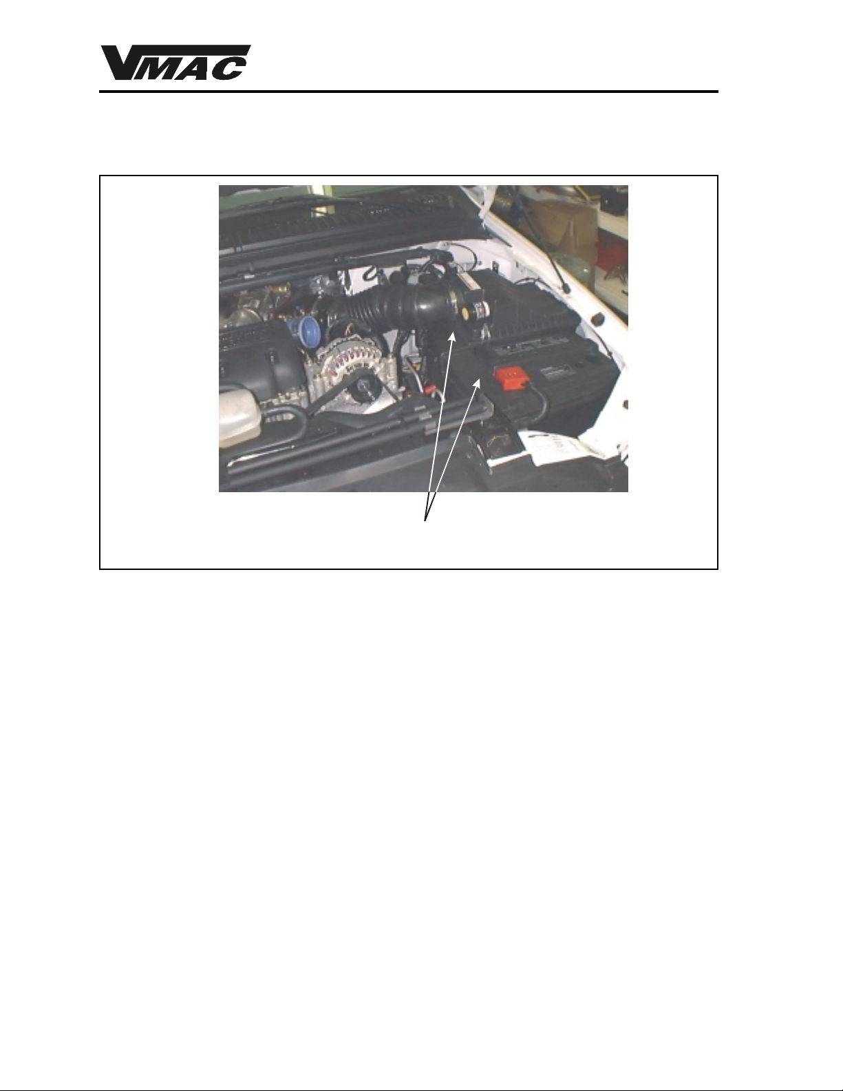
8. Disconnect the air inlet horn from the front of the air cleaner and battery box. Leave this
part in place. This is optional for ease of removal and installation. Remove the air cleaner
box and the battery box from the driver’s side of the vehicle (Figure 1.2).
Figure 1.2
9. Remove the alternator from its mount and lay it back on top of the engine. Keep the OEM
fasteners for alternator installation.
10. Remove the power steering pump pulley (noting the position of the pulley on the shaft), then
remove the power steering pump from the bracket. Keep the OEM fasteners for the power
steering pump installation. You will require the correct puller to remove the power steering
pump pulley.
11. Remove the power steering return hose from the power steering pump. Remove and
discard the metal portion of the hose.
12. Fasten the pump out of the way or lay it on the frame. Do not allow it to hang from the
pressure hose.
13. Remove and discard the OEM alternator and power steering pump mounting bracket and
the OEM bracket fasteners (Figure 1.3).
14. Peen the edge of the valve cover flat against the cylinder head in the area where the
compressor mounting bracket will attach. This allows the compressor mounting bracket to
sit flush with the cylinder head surface (Figure 1.3).
15. Remove and discard the upper and lower radiator hoses.
Remove The Air Cleaner And Battery Boxes
DOCUMENT 19352
Indice
Altri manuali Vmac Accessori per automobili

Vmac
Vmac V910020 Manuale di servizio

Vmac
Vmac A500237 Manuale utente

Vmac
Vmac A700308 Manuale utente

Vmac
Vmac VR7000 9039 Manuale utente

Vmac
Vmac A700137 Manuale utente

Vmac
Vmac VR 7000 9018 Manuale utente

Vmac
Vmac A500246 Manuale utente

Vmac
Vmac VR 7000 9004 Manuale utente

Vmac
Vmac A700269 Manuale utente

Vmac
Vmac A700247 Manuale utente


