Volvo L60F Manuale utente

MORE CARE. BUILT IN.
CONTENT
3 Electrical and Information System
Description
VOLVO CONSTRUCTION EQUIPMENT
SERVICE MANUAL
l60F/L70F/L90F


Foreword
This booklet is part of a complete service manual. Read the fore‐
word in the service manual.
WARNING!
Always read the booklet Safety before proceeding.
1
VOE 21 A 1002889


Content
30 GENERAL
300 Comprehensive info, electrical system
Electrical system, work instructions ............................................................ 5
Electrical system, description ..................................................................... 8
Electronic control system, description ...................................................... 10
Communication with data buses ............................................................... 12
Software, description ................................................................................ 13
Instrument control unit I-ECU, description ................................................ 14
Vehicle control unit V-ECU, description .................................................... 15
Vehicle control unit V2-ECU, description .................................................. 16
Engine control unit E-ECU, description .................................................... 16
Climate control unit ECC, description ....................................................... 17
31 BATTERY
310 General, common info about 311 - 313
Battery, description ................................................................................... 18
Battery, charging ....................................................................................... 19
Batteries, replacing ................................................................................... 20
System voltage ......................................................................................... 22
Key feed .................................................................................................... 22
32 ALTERNATOR; CHARGE REGULATOR
320 General, common info about 321 - 322
Alternator 80 A, description ...................................................................... 23
33 STARTING SYSTEM
331 Starter motor inclusive solenoid
Booting sequence ..................................................................................... 24
35 LIGHTING
350 General, common info about 351 - 356
Lighting, description .................................................................................. 25
36 OTHER ELECTRICAL EQUIPMENT
360 General, common info about 361 - 367
Reduced computer communication .......................................................... 28
Interruption in computer communication ................................................... 29
Limp Home ............................................................................................... 29
Intermittent wiper and washer ................................................................... 30
Theft protection ......................................................................................... 32
38 INSTRUMENT; SENSOR; WARNING AND INFORMATION
SYSTEM
380 General, common info about 383 - 387
Instruments ............................................................................................... 33
Instrument panels, position .................................................................... 33
Middle instrument panel with warning lights ............................................. 34
386 Sender, monitoring system
Washer fluid level ..................................................................................... 35
Fuel consumption ..................................................................................... 36
Travelling speed ....................................................................................... 37
Machine hours .......................................................................................... 37
387 Warning/information unit, display unit
Information display, general ...................................................................... 38
Information display, start lockout .............................................................. 41
Information display, operating display ...................................................... 42
Information display, engine ....................................................................... 43
Information display, transmission ............................................................. 45
3

Information display, hydraulics ................................................................. 46
Information display, axles / brakes ........................................................... 47
Information display, electrical system ....................................................... 48
Information display, vehicle info ................................................................ 49
Information display, vehicle messages ..................................................... 51
Information display, service ...................................................................... 52
Information display, service mode ............................................................ 53
Information display, settings ..................................................................... 55
Information display, check ........................................................................ 56
Alarm, description ..................................................................................... 57
Central warning ......................................................................................... 58
4

ELEC. SYSTEM; WARNING
SYSTEM; INFORMATION
SYSTEM; INSTRUMENTS
30 GENERAL
300 Comprehensive info, electrical
system
Electrical system, work instructions
Regarding: L60F, L70F, L90F
Batteries
1 Fully charged and otherwise satisfactory batteries must
always be used when working on the electrical system.
2 Test the batteries with an acid tester. The battery disconnect
switch should be turned off.
3 When installing a battery, make sure that the battery is con‐
nected with the correct polarity.
4 When changing batteries connected in series, make sure they
are of equal capacity, for example, 2 batteries of 105 Ah. The
batteries should have the same age (same quality), since the
charging current required to reach a certain voltage varies with
the battery's age.
5 If booster battery is required when starting, the following
instructions must be followed at all times;
191, Safety when
working with batteries
and
191, Starting with booster batter‐
ies
.
Charging
1 Before performing any tests of the alternator or regulator, the
batteries must be checked regarding insulation, loose fit, and
corrosion. Check the alternator belts.
2 For all testing of alternating current equipment, use “secure”
connections in order to prevent sparks and voltage transients.
A loose cable may result in destruction of both the alternator
and regulator.
3 Never disconnect the alternator leads while the engine is run‐
ning. This could damage both the alternator and regulator.
4 If the current alternator output socket should be connected to
the chassis, damage may occur to the alternator and regulator.
Components
When removing or installing components in the electrical system,
turn off the voltage supply with the battery disconnector.
5

Welding
For electric welding on the machine or on attachments on
machine:
- voltage feed turned off with battery disconnector
- connectors for all control units (ECUs) must be unplugged
NOTE! Ground the welding unit as close as possible to the weld‐
ing point.
6

Electrical system, description
Regarding: L60F, L70F, L90F
The machine has a 24 V electrical system with two 12 volt bat‐
teries connected in series, located on each side of the rear frame
in the counterweight.
The battery disconnector is located under the radiator casing.
Fuse FU74 is next to the battery disconnector and supplies volt‐
age to certain components (e.g., voltage converter for radio),
even when the battery disconnector is turned off.
Voltage feed takes place via a fuse box located in the engine
compartment. The fuse box contains main fuse as well as fuses
for preheating coil and secondary steering pump.
Relays and fuses are mainly located in the electrical distribution
box behind the operator's seat and are accessed by removing the
cover for the electrical distribution box. The cover's inside is pro‐
vided with a decal that informs which power-consuming compo‐
nent is connected to each relay and fuse. There is a built-in
terminal for fuse test in the electrical distribution box. The relays
in the electrical distribution box are interchangeable.
Components are marked according to which function group they
belong. The first two digits indicate function group and the other
digits are running numbers, e.g., SE2203.
NOTE! For working on the electrical system, follow the instruc‐
tions in section
Electrical system, work instructions page 5
.
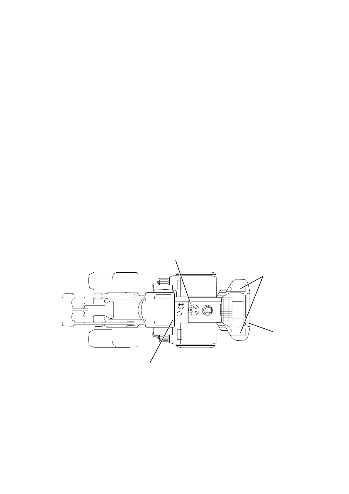
1
2
3
4
V1048614
Fig.1 Position
1 Fuse box
2 Batteries
3 Battery disconnector, fuse FU74
4 Electrical distribution box
8
Questo manuale è adatto per i seguenti modelli
2
Indice
Altri manuali Volvo Veicolo utilitario


