
VuQube V20 Manuale utente
11200 Hampshire Avenue South, Bloomington, MN 55438-2453
Phone: (800) 982-9920 Fax: (952) 922-8424
www.kingcontrols.com
20875 REV B
Digital TV Solutions for Mobile Markets
®
Automatic Satellite System
with built-in DVB for positive satellite identification
Model V20 Stationary
Model V30 In-Motion
Installation and Operating Instructions


Page 1
DIRECTV®is a registered trademark of DIRECTV, Inc.
Dish Network®is an official trademark of Echostar Communications Corporation.
Bell TV is an official trademark of Bell Canada.
DVB®is a trademark of the DVB Digital Video Broadcast Project (1991-1996)
TABLE OF CONTENTS
Section Contents Page
1. INTRODUCTION.....................................................................................2
2. INSTALLATION....................................................................................3-7
3. ANTENNA CONFIGURATION...........................................................9-20
4. OPERATION....................................................................................22-28
5. TROUBLESHOOTING..........................................................................29
6. MAINTENANCE....................................................................................30
7. LIMITED WARRANTY ..........................................................................31
IMPORTANT!
The satellite TV market is expanding and changing. The information in this manual was accurate at the time
of printing. If your VuQube does not operate as outlined in this manual please call King Controls at (800)
982-9920 or visit our website at www.kingcontrols.com.
This VuQube is factory pre-set for DIRECTV®standard digital programming broadcast from the
101° W satellite.
If you also receive your local channels from DIRECTV’s 119 satellite or if you subscribe to Dish Network®
or Bell TV programming, you must re-configure the antenna to work with your satellite service.
Doing this will allow the VuQube to lock on the correct satellites to receive your programming and also
enable automatic satellite switching via the receiver’s remote control for multi-satellite service.
Antenna configuration is a one time procedure that MUST BE COMPLETED before using your VuQube
antenna. See the ANTENNA CONFIGURATION section in this manual for specific instructions.
This VuQube must be installed with a King Controls bracket MB100, MB101 or MB200. Failure to use one of
these brackets will void the product warranty.
Please read this entire manual before beginning the installation.
Page 2
The VuQube V20 and V30 Automatic Satellite Systems provide simple, one-touch operation for easy
access to all your favorite satellite TV channels. They are full featured dish systems with automatic
satellite acquisition, satellite switching capabilities, and for the V30, in-motion capabilities.
The V20 and V30 are compatible with the following satellite services:
DIRECTV Single Satellite 101
DIRECTV Plus
Dish Network Dish 500 and Dish HD Eastern Arc
Dish Network HDTV (Dish HD Western and Eastern Arc with Locals, and Dish HD Alternate)
Bell TV satellites 82 and 91
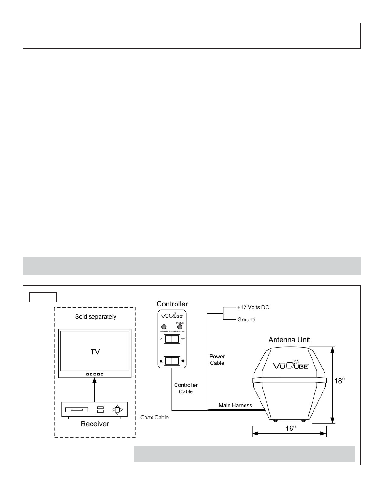
The V20 and V30 include 2 main components (Fig. 1).
Antenna Unit Located on the outside of the vehicle. The dish is covered by a
protective enclosure that keeps operational components free from
the elements.
Controller Located in the vehicle. Activates the search mode and provides limited
diagnostic functions using the status light.
SECTION 1 INTRODUCTION
Note: A TV, satellite receiver, and program subscription are also required for satellite TV viewing (sold separately).
Note: Overview only. See Installation Section for complete wiring diagram.
Fig. 1
Page 3
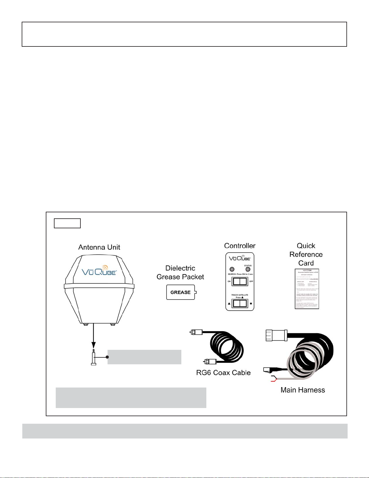
IMPORTANT! You must remove the shipping bolt from the bottom of the unit.
2. Unpack and identify all components (Fig. 2).
3. Remove and discard the shipping bolt from the bottom of the unit (Fig. 2).
SECTION 2 INSTALLATION
Fig. 2
TOOLS AND MATERIALS REQUIRED / KIT CONTENTS
1. Read thru the instructions and make sure you have all the tools and materials required to
complete the installation, including:
• King Controls mounting bracket (sold separately - for more information call King
Controls at 800-982-9920 or visit our website at www.kingcontrols.com)
FAILURE TO USE AN APPROVED KING CONTROLS MOUNTING BRACKET WILL
VOID THE PRODUCT WARRANTY.
• drill and drill bit set
• tape measure
• 7/16” open end wrench (coax connections)
• adhesive sealant (compatible with cab material)
• appropriate tools and fasteners to install all components and wiring
• 5/32” allen wrench, channel lock or pliers (to remove shipping bolt)
KIT CONTENTS
IMPORTANT! You must remove the shipping bolt
from the bottom of the unit prior to installation.
REMOVE BOLT!
Page 4
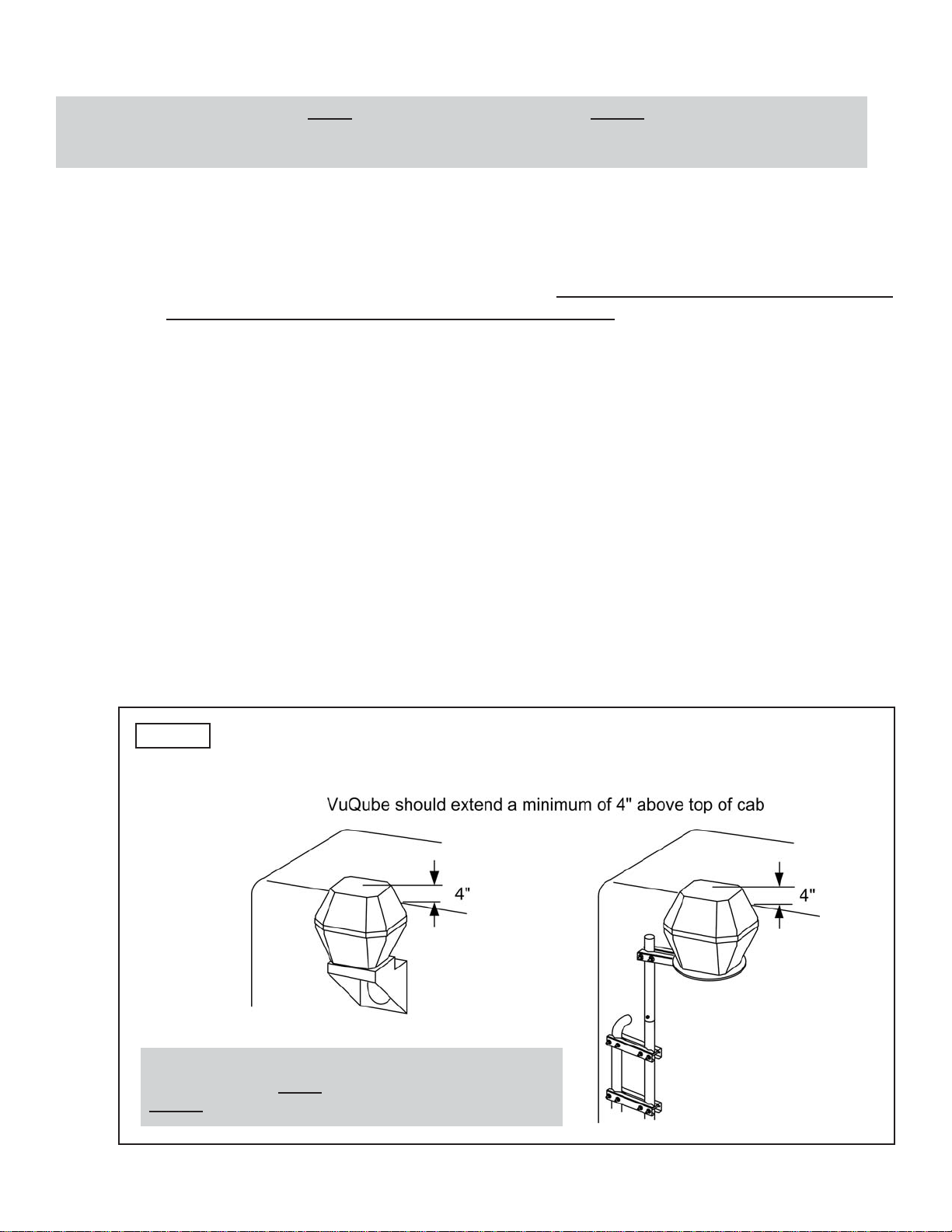
ANTENNA UNIT LOCATION AND INSTALLATION (FIG 3.)
4. Determine the mounting location of the antenna unit using the following criteria:
a) The antenna unit is designed to be mounted to a vehicle with either an MB100, MB101
or MB200 mounting bracket (sold separately - for more information call King Controls
or visit our website at www.kingcontrols.com). FAILURE TO USE THE APPROPRIATE
BRACKET WILL VOID THE PRODUCT WARRANTY.
b) The antenna unit requires a 16” wide space for mounting.
c) It is highly recommended that the antenna unit extend a minimum of 4” above the
highest point of the cab or air shield for optimum satellite reception.
If you are unable to mount the antenna unit 4” above the cab due to height restrictions,
install with maximum clearance available. If the antenna unit is not high enough, you
may experience difficulty acquiring the satellite signal.
d) The antenna unit should be as far as possible from objects like smoke stacks, beacons,
logistic units, etc. that can physically block the satellite signal.
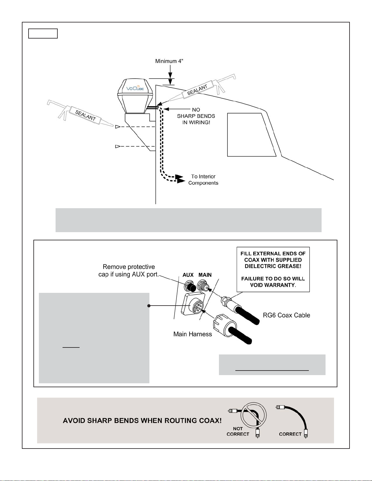
e) The wiring from the antenna unit may be run down the back of the cab and up into the
cab through an access bay, or a hole may be drilled in an appropriate location. There
must be no sharp bends in the wiring.
IMPORTANT! The antenna unit MUST be mounted to the air ride cab, NEVER to any structure mounted
directly to the frame (for example the headache rack). Mounting directly to the frame will
void the product warranty.
Fig. 3
IMPORTANT
The antenna unit MUST be mounted to the air ride cab,
NEVER to any structure mounted directly to the frame.
MB100 or MB101 Mounting Bracket
(Sold separately) MB200 Mounting Bracket
(Sold separately)
Page 5
5. Mount the bracket to the cab (see bracket instructions-bracket sold separately).
6. MAKE SURE THE SHIPPING BOLT IS REMOVED FROM THE BOTTOM OF THE UNIT
(SEE PAGE 3).
7. Remove the bolts and lock washers from the bottom of the unit. Set the unit in place. THE
WIRING CONNECTIONS MUST FACE FORWARD (TOWARD THE FRONT OF THE
VEHICLE).
8. Install the bolts and lock washers up thru the mounting bracket and into the unit. Tighten
bolts securely.
EXTERNAL WIRING (FIG. 4, PAGE 6)
9. Plug main harness into wiring port on back of antenna unit and tighten connection until it
clicks past the detent lock.
10. Fill end of coax cable that will connect to the MAIN port on the antenna unit with supplied
dielectric grease. Connect this end of the coax cable to the MAIN port and tighten
connection. DO NOT OVER TIGHTEN.
If using a second receiver, fill end of second coax cable (not supplied) and connect it to the
port labeled AUX. Tighten connection. DO NOT OVER TIGHTEN.
11. Run wiring from the antenna unit to the location where it will be fed into the vehicle. Make
sure external wiring is tied down securely (to a hand rail for example).
12. Drill 3/4” hole through the cab or use an existing hole to feed the wiring inside. Seal opening
with cab compatible sealant so that it is entirely waterproof (inside and outside of the hole).
Note: The installer is responsible for determining the most appropriate fasteners to secure the mounting bracket to the
cab, and they should always be used in combination with a cab compatible sealant.
IMPORTANT! The installer is responsible for weatherproofing all holes with sealant.
Note: The VuQube is wired for multiple receiver support. There are two coax ports on the back of the unit. The one
labeled “MAIN” MUST be connected to the main receiver in the vehicle. This receiver will control automatic
satellite switching if applicable. The one labeled “AUX” can be used for an additional receiver.
IMPORTANT! You must fill the ends of the external coax cables with the supplied dielectric grease.
Failure to do so will void the product warranty.
Page 6
Fig. 4 TYPICAL CAB INSTALLATION USING THE MB100 BRACKET
(Bracket sold separately)
Coax connections should be snug.
DO NOT OVER TIGHTEN!
IMPORTANT!
The alignment tabs on the wiring
port and the main harness plug
must match up when engaging
plug onto port.
YOU MUST TIGHTEN THE PLUG
UNTIL IT CLICKS PAST THE
DETENT LOCK.
(A channel lock pliers may be used
to carefully tighten the connection.)
IMPORTANT! Bracket mounting holes and wiring hole must be sealed so they are
completely waterproof. Sealant must be cab compatible.
Page 7
INTERNAL WIRING
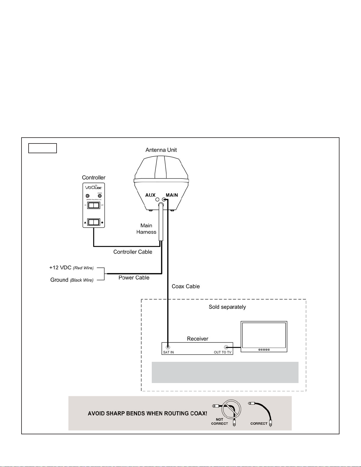
13. Inside the vehicle, make the connections as shown in (Fig. 5), keeping in mind the following
important points:
a) The connection between the antenna unit and the receiver must be a direct
connection with no devices in between.
b) Power connection must be a non-shared circuit. Excessive current draw on the
circuit will cause the unit to operate improperly. Power and ground connections must be
made after the main harness is plugged into the antenna unit.
c) If fusing the circuit, the fuse must be rated at 7.5 amps.
Fig. 5
Note: HDTV receivers require HDMI or component
video/audio cable connection to TV.

This page intentionally left blank.
Page 8
Altri manuali per V20
2
Questo manuale è adatto per i seguenti modelli
1
Indice
Altri manuali VuQube Sistema TV satellitare


