Warmington Evoque 1300 Manuale utente
23 March 2017
Due to continued product improvement, Warmington Ind LTD reserves the right to change product specifications without prior notification.
All Dimension are in mm……….Copyright
1
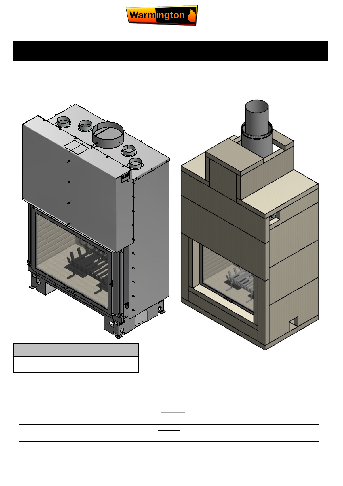
Solid fuel burner, bricked fire
Installation Instructions
Warmington Evoque 1300
Fire, flue system and instructions to comply with ASNZS 2918:2001 & Building Code C1 Outbreak of Fire
Keep these Instructions for further reference. Ensure that you have the correct and current installation details for the Warmington Fire
Installation
The Warmington unit is to be installed by a certified Warmington installer or an Approved NZHHA Installation Technician.
IMPORTANT
Read all the instructions carefully before commencing the Installation. Failure to follow these instructions may result in a fire hazard and void the warranty
Note flue system casing:
Flue system may require to be doubled lined to comply to
ASNZS:2918:2001 4.3 Flue pipe casing.
23 March 2017
Due to continued product improvement, Warmington Ind LTD reserves the right to change product specifications without prior notification.
All Dimension are in mm……….Copyright
2
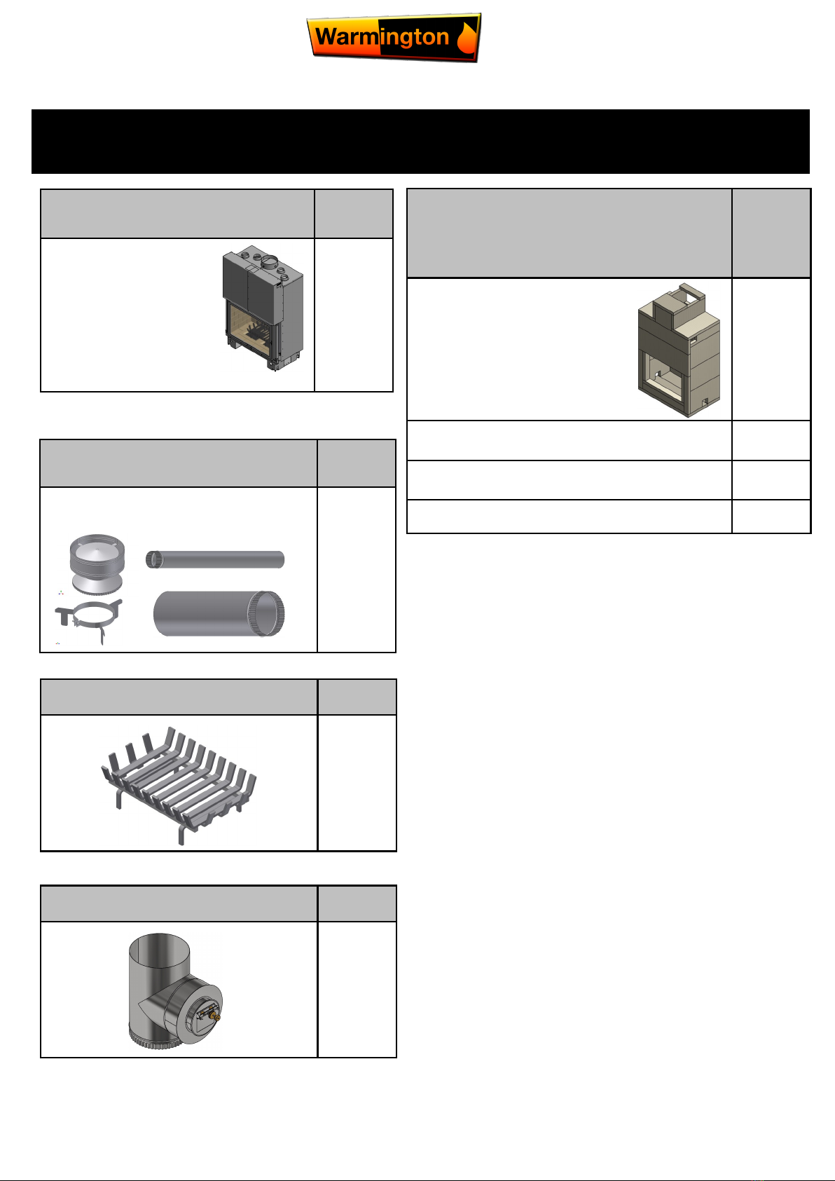
Supplied as traditional
firebox
No:
Traditional firebox 1
Supplied
Priced depending on requirements
No:
Warmington flue kit 1
NOT supplied
components are required for in-
stall
Priced depending on requirements
No:
Autoclaved Concrete
(ACC) heat cell
1
Installation -
Fire/flue kit/flashing
Installation
Council permit
Components required for construction
(SUPPLIED SEPARATLEY)
Supplied grate No:
1
Downdraft diverter No:
1

23 March 2017
Due to continued product improvement, Warmington Ind LTD reserves the right to change product specifications without prior notification.
All Dimension are in mm……….Copyright
3
POINTS TO CONSIDER PRIOR TO INSTALLATION
Prior to construction and installation IMORTANT NOTES:
Install to AS/NZS 2918:2001.
Install to manufacture’s specifications.
All new installations require a permit.
For special requirements concerning materials (timber mantle and surrounds) within close proximity of Warmington products, please contact your
local Warmington technical consultant or designated installer.
Stage 1: Frame construction procedure by builder.
Mark out flue centre on floor.
Mark out heat cell clearance requirements.
Construct plinth only, to required height.*
Stage 2: Install procedure by certified “Warmington Installer” or see www.homeheat.co.nz go to ”members” & follow instructions. For an
NZHHA certified SFAIT installer.
Fit fire to plinth.
Fit adaptor to firebox.
Construct Autoclaved Concrete (ACC) enclosure around the firebox.
Fit flue system.
Fit cowl and flashing system.
Stage 3: Finishing procedure by builder.
Construct hearth to required thickness.*
Finish Autoclaved Concrete (ACC) enclosure and hearth to customers requirements (e.g. paint/tiles).
Close in Autoclaved Concrete (ACC) enclose and chimney chase (if in timber alcove).
* Note: A certified installer can also install hearth and plinth.
Ensure that the Warmington and flue system is swept annually or more frequently if required. To sweep flue and firebox:
Cover front of fire with sheets, or keep door closed during sweeping.
Remove cowl from top of chimney.
Sweep from the top, down the flue.
Remove all soot and ash.
Ensure cowl and bird protection is clean and replaced.
Visually inspect fireplace and flue system.
INSTALLATION ORDER OF OPERATIONS installation is not provided
Location of the fire.
Open fires are better located at one end of a room or area, as they project the heat away from their opening.
The topography of the land.
The slope and position of the land in relation to the home has a bearing on how the wind will interact with the fire and flue system. Care needs to be taken to ensure that the flue
termination is in the correct position to maximise performance.
The Prevailing wind.
Care needs to be taken to ensure that the flue termination is in the correct position as wind and gusts that hits the flue and cowl system may overcome the cowl and draft back down
the flue into the home. This can be a combination of downdraft and high pressure.
Hearth and plinth:
The height of the hearth off the floor. The finishing that is to be used on the hearth is to be allowed for at the design stage.
Note: ensure air intake at base of firebox is not blocked or restricted.
Positioning of the flue system:
There is a maximum distance that an offset flue can be installed. Reference to AS/NZS 2918:2001.
Flue and fire clearance:
To be maintained to the manufactures instructions and/or comply with appropriate standards and building codes.
Pressure differential, venting and external air into the building:
All fires need air to burn and draw correctly, Kitchen Fans, Air Conditioning units, High Wind Zones, Naturally forming Draft spaces, can all have an effect on the pressure difference
from inside the building to the outside. A lower pressure in the building may induce a draft down the flue system and back into the building causing the fire to smoke or spill into the
building. Care needs to be taken at the design and installation stage to adequately vent the building, or some mechanical system to ensure that there is always a neutral or
positive pressure at the fireplace and a negative pressure at the flue outlet. This will ensure that the draft in the flue system is always to the outside.
Wind Noise:
You may encounter wind noise in some installations. It is recommended to use an enclosed chase with a chimney pot to help reduce noise. There will always be some noise from the
flue systems of all fireplaces.
Installation Notes:
Due to the expansion and contraction of metal fireplaces a 3mm gap between the flange and the finished surround should be maintained.
23 March 2017
Due to continued product improvement, Warmington Ind LTD reserves the right to change product specifications without prior notification.
All Dimension are in mm……….Copyright
4
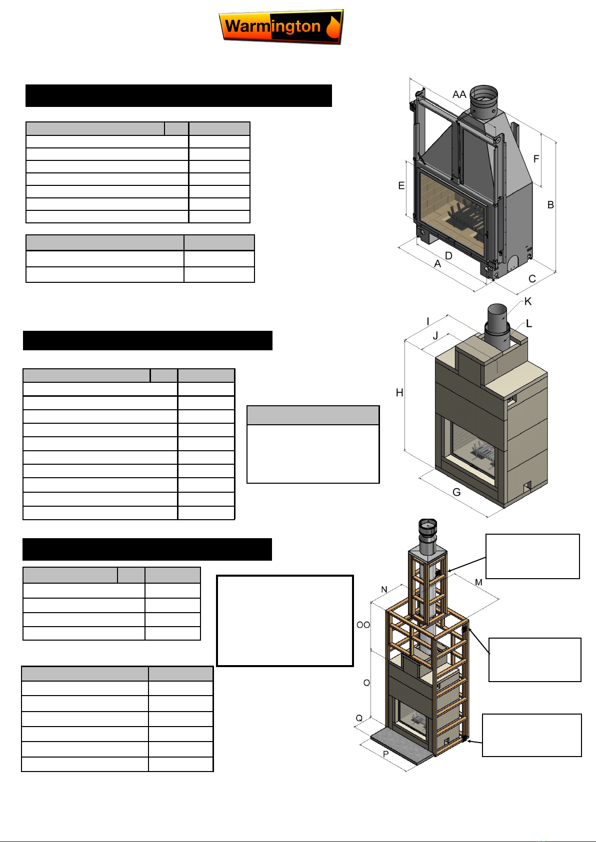
Description Evoque
Firebox Width A1216
Widest Part with Rail Burner AA 1385
Firebox Height B1790
Firebox Depth C620
Door Width D1100
Door Height E750
Adaptor Height F740
EVOQUE FIREBOX DIMENSIONS
ACC HEAT CELL DETAILS DIMENSIONS
Description Evoque
Heat Cell Width G1552
Heat Cell Height H2170
Heat Cell Depth I980
To Centre of Flue J624
Flue Diameter K300
Liner Diameter L400
Heat Cell Clearance Width M1602
Heat Cell Clearance Depth N1105
Heat Cell Clearance Height O2420
Chimney Clearance Height OO 1500
Minimum Flue Height
Flue Height 3600
Measured From Top of Adaptor B + F + 3600
Check List
Firebox
Grate
Ash Pan & Ash Tray
Draft Diverter
Bricks
Packed by
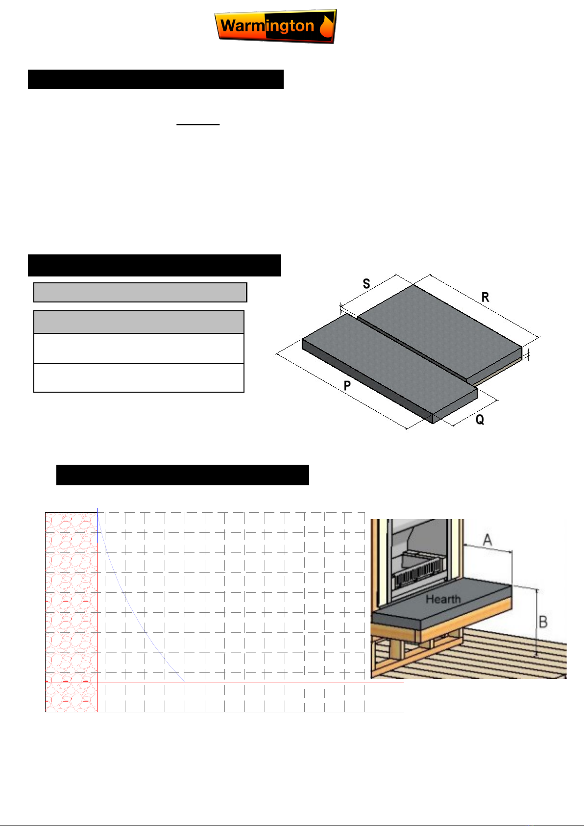
Description Evoque
Hearth Width P1552
Hearth Projection Q600
Plinth Width R1552
Plinth Depth S980
ACC HEARTH & PLINTH DIMENSIONS
See next Page 5 for Plinth & Hearth
Note: Chimney Chase
No combustible material
installed above the fire or in
the chimney chase below
1500 mm from the top of the
fire.
NOTE: Access panels
for servicing and ad-
justing the downdraft
diverter and sprockets
needs to be installed.
2x 165mm air vents
for external air into
the cavity.
2x 165mm air vent
outlets into the
room.
2x 165mm air vent
outlets to cool chim-
ney cavity to outside.
23 March 2017
Due to continued product improvement, Warmington Ind LTD reserves the right to change product specifications without prior notification.
All Dimension are in mm……….Copyright
5
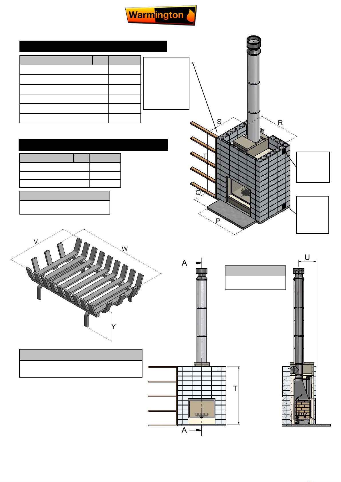
ENCLOSURE (WITH ACC HEAT CELL)
Description Evoque
Hearth Width P1675
Hearth Projection Q600
Block Clearance Width R1610
Block Clearance Depth S1200
Block Enclosure Height T2390
Distance to centre of flue U714
NOTE: WITH
BLOCK HEAT
CELL
Timber Framing
can be in direct
contact with
brick alcove.
Note:
Centre line of flue is `NOT’
in centre of alcove
Description GRATE
Grate Depth V410
Grate Width W605
Grate Height X195
Important Note
The fire has to be installed and run with the supplied
Warmington grate to comply with AS/NZS 2918:2001
Important Note
Do not load the fire with more than
5kg of softwood.
GRATE
2x 165mm
air vents for
external air
into the
cavity.
2x 165mm
air vent out-
lets into the
room.
23 March 2017
Due to continued product improvement, Warmington Ind LTD reserves the right to change product specifications without prior notification.
All Dimension are in mm……….Copyright
6
FIREBOX INSTALLATION
This is a general installation guide only – contact a “NZHHA Installer” for installation advice or go to
www.homeheat.co.nz then select Members & follow instructions, to find a certified NZHHA SFAIT installer.
1. All the dimensions are minimums
2. Fit the plinth into position in the cavity. If onto a wooden floor ensure that an insulating plinth is fitted as per specifications. En-
sure that the plinth is elevated to allow for finishing on the hearth (see hearth and plinth details).
3. Fit the firebox into the cavity. Bolt the fire box to the plinth or through to the floor with the bolting point provided on the left and
right hand side of the firebox or drill holes through base for bolts (seismic restraints bolts not provided).
4. Install the flue system. Ensure that the flue system comply to the latest AS/NZS 2918:2001.
5. Fit the Autoclaved Concrete (ACC) heat cell around the fire. A general minimum lay out is shown in this specification.
Note: hearth and plinth construction.
For combustible flooring an insulating hearth and plinth of
75mm Autoclaved Concrete (ACC) is required.
Plinth to be off set above hearth by the hearth finishing
(e.g. tiles/granite/plaster/etc.)
IMPORTANT NOTE:
*Note: If solid plastering the heat cell structure, it is rec-
ommended to use a fibreglass mesh with a latex plaster
to minimise the chance of the plaster cracking (see your
plasterer for correct materials and applications).
Offset
Offset for
Hearth
Finishing
Hearth
Plinth
HEARTH & PLINTH CONSTRUCTION DETAILS
HEARTH PROJECTION
380
400
450
500
550
600
650
700
750
800
850
900
Minimum Specified
Thickness
100
150
200
250
300
350
450
400
500
Hearth Projection mm (A)
Raised Hearth Height mm (B)
75
900
900
900
Minimum Hearth Projection 380mm (A)
380
23 March 2017
Due to continued product improvement, Warmington Ind LTD reserves the right to change product specifications without prior notification.
All Dimension are in mm……….Copyright
7
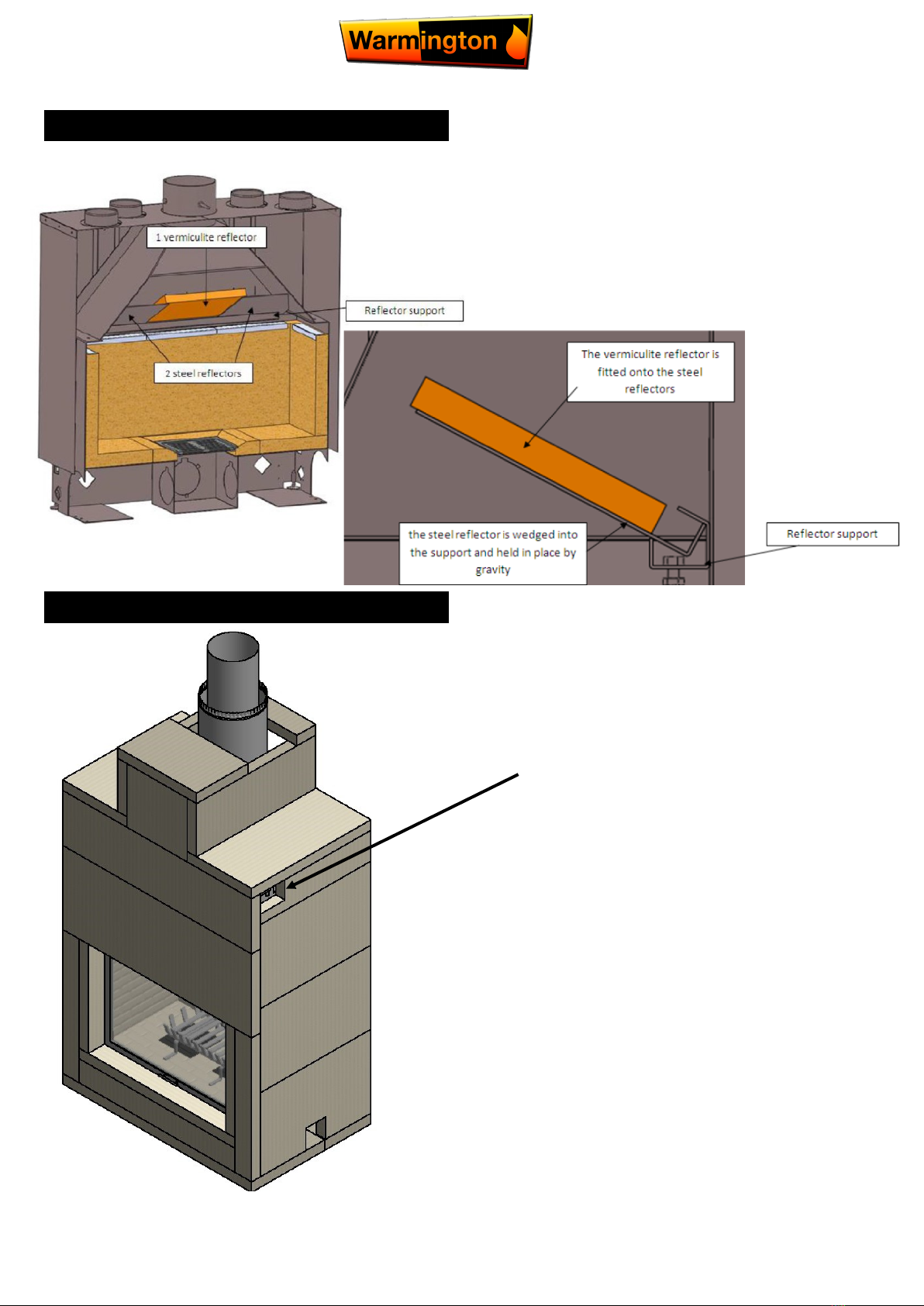
BAFFLE POSITION
CHAIN AND SPROCKET ACCESS CHANNEL
Location where the sprocket and
chain access panel is located.
Needs to be accessible for ser-
vicing, maintenance and lubri-
cation.
23 March 2017
Due to continued product improvement, Warmington Ind LTD reserves the right to change product specifications without prior notification.
All Dimension are in mm……….Copyright
8
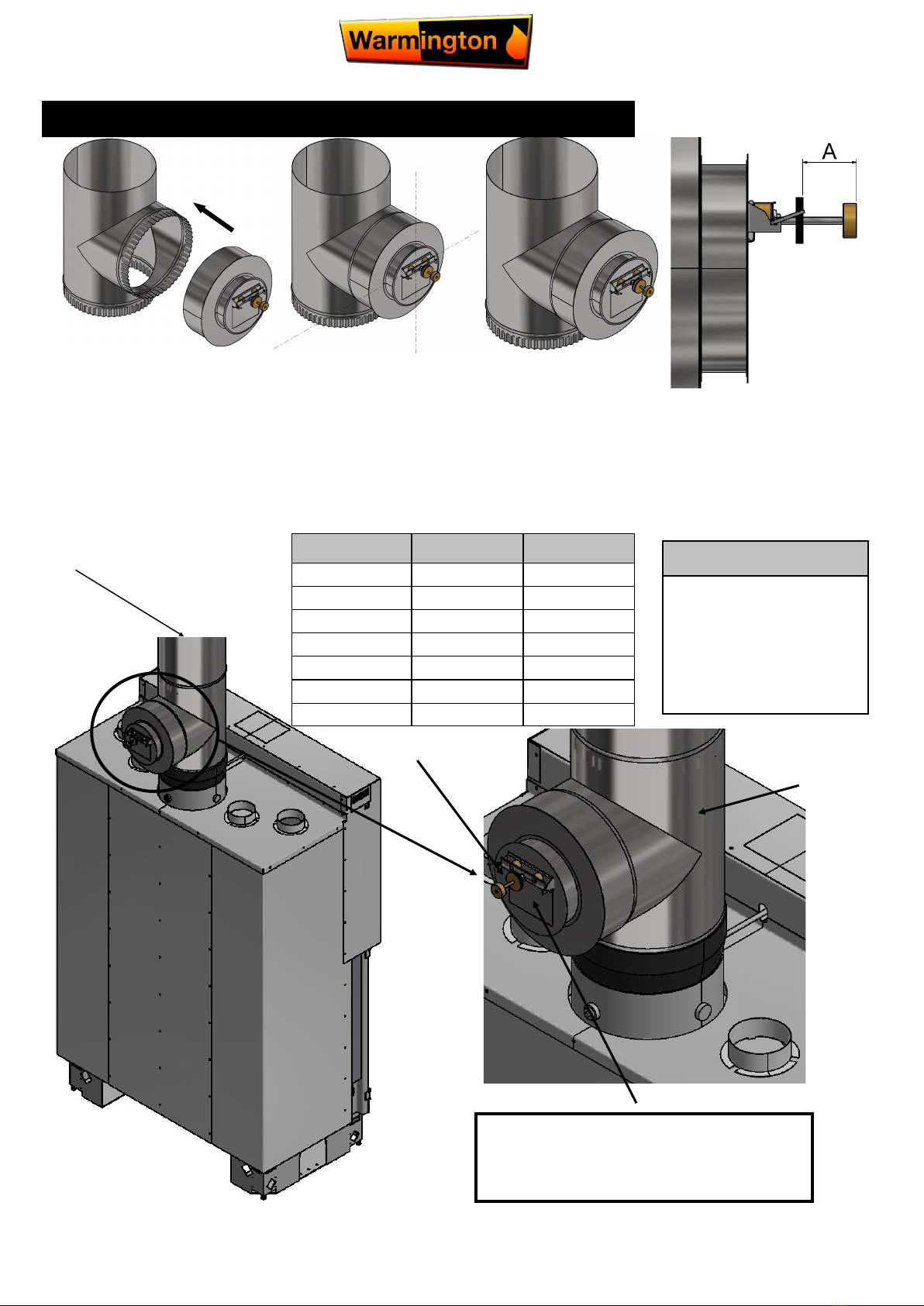
Installation onto a stainless tee-flue:
1. Set the draft diverter on the tee branch by fitting it as tight as possible to the tee.
2. Check that the valve is perfectly horizontal using a spirit-level, and rivet to the tee flue.
3. The adjustment of the draft diverter depends on the draft. With a standard 3.6 metre of flue dimension A is set to
12mm. If extra lengths of flue is installed the “A” distance in mm corresponds on the pressure in PA, 1mm = 1Pa, this can
be approximated by reading the chart below. Adjust the counter weight to the required distance by rolling it on its axis then
fix it by tightening the brass disks against each other, note that the thick brass disk always is at the end of the rod. To un-
lock the draft stabiliser, turn the stop in clockwise direction. This is done to keep a stable draft in the flue; more draft will
require less counterweight to regulate the draft.
DOWNDRAFT DIVERTER
Flue
Downdraft
diverter
Adjustment weights
Flap
NOTE: Access panels for servicing
and adjusting the downdraft diverter
needs and sprockets to be installed.
Flue Height Pressure A
3.6 metre 12 Pa 12 mm
4.2 metre 14 Pa 14 mm
4.8 metre 16 Pa 16 mm
5.4 metre 18 Pa 18 mm
6.0 metre 20 Pa 20 mm
6.6 metre 22 Pa 22 mm
7.2 metre 24 Pa 24 mm
Note: Positioning
The position of the draft
diverter is set to the ori-
entation that ensures
the best and easiest
access to the opening
face.
23 March 2017
Due to continued product improvement, Warmington Ind LTD reserves the right to change product specifications without prior notification.
All Dimension are in mm……….Copyright
9
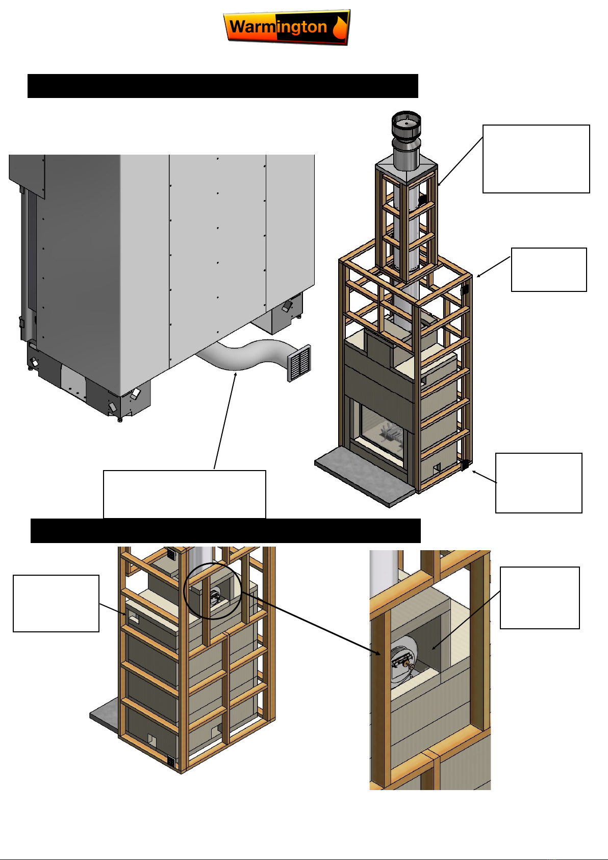
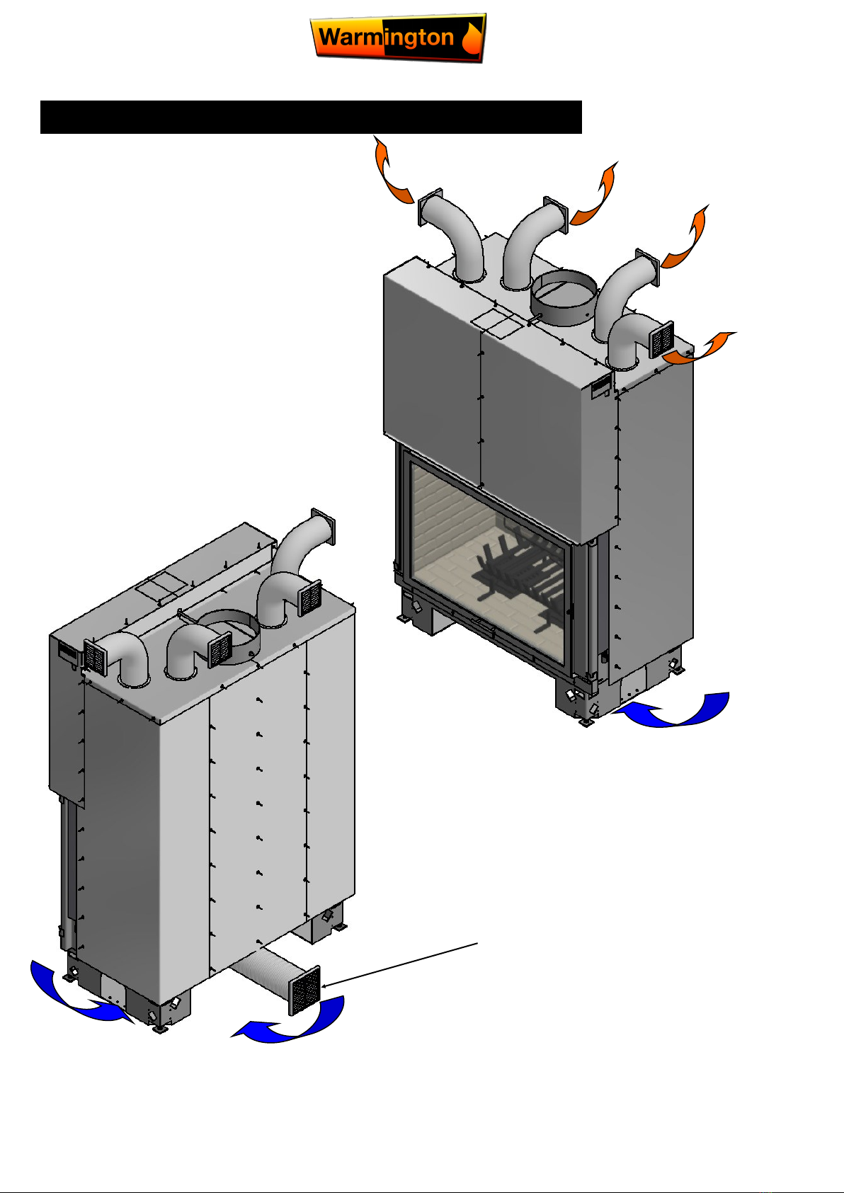
AIR INTAKE
ACCESS PANNELS
Access needed for
servicing the
sprockets on both
sides.
2x 165mm air
vent outlets into
the room.
2x 165mm air vent out-
lets to cool chimney
cavity to outside. Note:
venting cone can be
used instead.
1x 150mm aluminium flexi pipe to
be directly connected to firebox
flange from external air (outside air).
Access needed
for servicing and
adjusting the
draft diverter.
2x 165mm air
vents for external
air (from outside)
into the cavity.
23 March 2017
Due to continued product improvement, Warmington Ind LTD reserves the right to change product specifications without prior notification.
All Dimension are in mm……….Copyright
10
VENTING CONCEPT
Warm Air
Return to
Room
Vent Grill
NOT
Provided
Cavity Air
Venting
Cool Air In
Combustion Air Supply
Connected to ash pan air intake
Altri manuali per Evoque 1300
1
Indice
Altri manuali Warmington Stufa


