
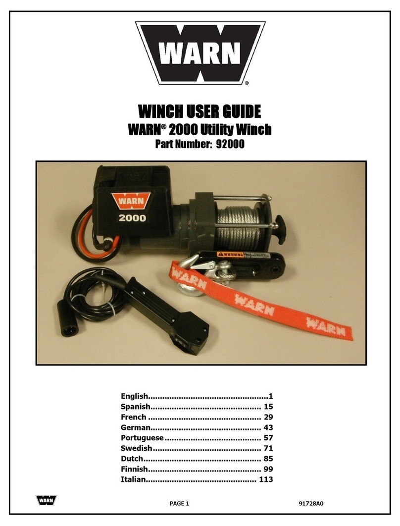
Warn A2000 Manuale utente

1
SERVICE GUIDE
FOR THE
WARN
ATV and Utility Winches
A2000, A2500, T2500, U2500,
P2500, Z3500, Pull Pack
12V DC
Electric Winch
REPAIR / REPLACEMENT INSTRUCTIONS
TROUBLE SHOOTING GUIDE
This guide has been provided for use by Warn Authorized Service Centers. Any other
use is prohibited.
This guide identifies potential hazards and has important safety messages that help
you and others avoid personal injury or death. WARNING and CAUTION are signal
words that identify the level of hazard. These signal words mean:
WARNING signals a hazard that could cause serious injury or death, if you do not
follow recommendations.
CAUTION signals a hazard that may cause minor to moderate injury, if you do not
follow recommendations.
This guide uses NOTICE to call attention to important mechanical information, and
Note: to emphasize general information worthy of special attention
Warn Industries, Inc
12900 SE Capps Road
Clackamas, OR 97015 USA

2
TABLE OF CONTENTS
SECTION 1 - GETTING STARTED--------------------------------3
1.1 WINCH MODEL IDENTIFICATION--------------------------------------------------------3
1.2 DEFINITIONS AND WINCH OPERATION------------------------------------------------4
SECTION 2 –DISASSEMBLY & REASSEMBLY--------------7
2.1 SERVICE TECHNICIAN REPAIRS ---------------------------------------------------------7
2.2 SUGGESTED TOOLS --------------------------------------------------------------------------7
2.3 DISASSEMBLY/REASSEMBLY-------------------------------------------------------------7
SECTION 3 –BRAKE REMOVAL AND REPLACEMENT--18
3.1 SUGGESTED TOOLS ------------------------------------------------------------------------ 18
3.2 DISASSEMBLY ------------------------------------------------------------------------------- 18
3.3 REASSEMBLY/ NEW BRAKE INSTALLATION -------------------------------------- 20
SECTION 4 –CONTROL PACK OVERVIEW AND WIRING
REFERENCE----------------------------------------------------------- 22
4.1 OVERVIEW OF CONTROL OPERATION---------------------------------------------- 21
SECTION 5 –WINCH TROUBLE SHOOTING--------------- 26

3
SECTION 1 - Getting Started
1.1Winch Model Identification
To ensure proper winch repair it is necessary to correctly identify the model and part number of
your winch. This makes ordering replacement parts easier, and helps you obtain the necessary
information from your Authorized Service Center. NOTE: For a part description, item
number and quantity, refer to the Replacement Parts List in this manual for your
specific winch model.
WINCH IDENTIFICATION: label is located on the clutch end housing; this information
covers the winch and the pull rating.
WINCH BUILD DATE: build date of the winch is located on the cable protectors, motor end or
clutch housing end. The date code, (ex.) 3201A- gives the week, year, 32nd week of 2001 line A.
Figure 1.1 Locations of Product Build Date

4
1.2 Definitions And Winch Operation
1.2.1 Definitions
Operation and service of a Warn planetary winch can be explained easier by defining a few major
structural components. Refer to Figure 1.2 for the following definitions:
MOTOR: The winch motor is a permanent magnet motor. A 12-volt DC battery powers the
electric motor.
DRUM: The winch drum is the structural component of the winch used to store wire rope and
to transmit torque from the winch motor and gears to the wire rope.
DRUM SUPPORT: Drum supports (covered by housing) are the structural components of the
winch that mount the winch to the vehicle. The drum rotates while being held by the drum
supports and both the motor and gear train are attached to a drum support.
GEAR TRAIN: Warn electric planetary winches consist of a gear train made up of three
planetary gear stages. The purpose of the gear train is to multiply motor torque and to reduce
motor speed transmitted to the drum. Warn gear trains are enclosed in a housing and are
lubricated with grease.
FREESPOOL CLUTCH: A freespool clutch is incorporated in the gear train to allow the user
to pull the wire rope off the drum to the anchor point where the hook will be attached, without
using the winch motor. This is referred to as "Free spooling".
Figure 1.2 Major Winch Components
Drum Support
Motor
Free spool Clutch
Drum w/ Wire Rope
Gear Train

5
MOTOR CONTROLS: The electric winch motor is controlled by a control pack (contactor),
ATV switch, or a rocker switch. The 12-volt battery power source feeds the electric cables that
are connected to these controllers. The main function is to allow the winch to function in both
directions.
POWER-IN and POWER-OUT - Terms used to describe winch operation. When the wire rope
is reeled in under motor power, it is being "powered in". When the wire rope is reeled out
under motor power it is being "powered out". (This is different than when the winch is
"freespooled out", which refers to the wire rope being pulled out by hand with the freespool
clutch disengaged.)
1.2.2 Winch Operation
The ATV winch is designed to pull loads in length to approx.48.5 ft. The Utility winch will
pull up to approx. 58.5ft.
(Refer to Figure 1.2 when reading the following section). The vehicle battery and charging
system generates the power for pulling the load.
Power feeds from the battery power source into the winch control pack. At the push of a
control switch the power flows to the winch motor.
Motor Cable (Yellow /#1)
Positive Battery Cable
Motor Cable (Blue/#2)
Control Pack Ground Cable
Remote Socket Wiring
Motor Cable (Blue/#2)
Positive Battery Cable
Motor Cable (Yellow/ #1)
Control Pack Ground Cable

6
The winch motor turns the electrical energy into mechanical energy. The motor shaft powers
the gears, which in turn pulls the load. For the winches with a brake, it will hold the load if
user must stop.
On power-in operation, the drive shaft rotates and drives the planetary gears, starting with the
gear carrier stage farthest from the winch drum (the first stage carrier.) The first stage carrier,
in turn, drives the second stage carrier, which then drives the third stage carrier. The third
stage directly drives the drum. Since the wire rope is connected to the drum, the rope winds
around the drum, causing the load to be drawn in.
On power-out operation, the motor is reversed and the winch drum is rotated in the opposite
direction. All winch components operate in the same manner as during power-in.
In stopped position, the switch activates the “dynamic braking” effect of the motor , resisting
additional turning of the wire rope drum.
NOTES:

7
SECTION 2 –Disassembly & Assembly
2.1 Service Technician Repairs
WARNING
Personal Injury
Failure to observe these instructions could lead to severe injury or death.
READ THIS BEFORE BEGINNING REPAIRS
This manual is intended for use by a WARN authorized service technician. It is
important that you make repairs with the proper tools and equipment. It is also
important to correctly follow the instructions. Failure to do so, may cause the winch
to fail.
2.2 Suggested Tools
The following tools are suggested for these procedures: Hex 3/16 Allen wrench,
Torque wrench, 1/2, 7/16, 3/8, and 5/16 sockets, 3/8 & 7/16 box end wrench, needle
nose pliers, and one flat blade screwdriver.
2.3 Disassembly
WARNING
Personal Injury
Failure to observe these instructions could lead to severe injury or death.
Never lean over battery while making connections
Always disconnect all wires from battery, before beginning work.
Always disconnect negative terminal first and reconnect negative terminal last.
Always remove jewelry and wear eye protection.

8
MOTOR REMOVAL:
Note the motor placement for correct
replacement before any removal, also
checking and marking any wires that
will be removed.
Repairs are easier and safer when
winch is removed from vehicle and
located on a workbench.
Secure wire rope with rope or electrical
tape to prevent flaring.
Remove motor with housing and drum
support from the drum by removing the
two ¼-20x5/8 tie rod screws with the hex
Allen wrench or Torque wrench.
If “not” replacing the armature, the
cap assembly must be taped to the
body of the motor case to prevent
springs pushing cap off and allowing
brushes to become dislodged.
Motor is removed from motor housing by
removing the two motor bolts located on
top of the motor cap.

9
At this time the cap assembly may be
removed, and checked for wear, corrosion,
and electrical terminals that may have
been damaged or over-tightened.
ARMATURE REMOVAL:
Placing shaft end on the bench and
pushing case down, pulling the armature
out at the top will remove the armature.
Check the armature for broken wires,
burned, or excessive wear on the
commutator.
If any of these problems are present the
armature must be replaced, also the case
must be cleaned with alcohol or similar
cleaner.

10
ARMATURE REPLACEMENT:
To replace the armature, it is slid in from
the bottom of the casing, which is
identified by the magnets closer to one end
of the case. If there is resistance to the
armature placement, it is the wrong
direction.
Inspect housing closely, as some motor
housings can be damaged by excessive
heat or damaged from a hit.
MOTOR REPLACEMENT:
Motor cannot be installed until the drum
support plate is removed and 1st stage
planetary gear with sun gear, or brake.
The two motor bolt nuts will be found
inside the housing.
.
Inspect housing, as some housings can be
damaged by excessive dirt/mud or
damaged from a hit.
.
Check that the brass bushing and thin
washer are in place, position the motor
shaft through the bushing and washer.
Questo manuale è adatto per i seguenti modelli
6
Indice
Altri manuali Warn Verricello

Warn
Warn 72492 Manuale utente
Warn
Warn 2000 Manuale utente

Warn
Warn 2.5ci Manuale utente

Warn
Warn ZEON Manuale utente

Warn
Warn 70924 Manuale utente

Warn
Warn 93790 Manuale utente

Warn
Warn PN 61020 Manuale utente

Warn
Warn 84704 Manuale utente

Warn
Warn 84705 Manuale utente

Warn
Warn 90250 Guida alla risoluzione dei problemi

Warn
Warn ZEON Specifiche

Warn
Warn 60272 Manuale utente

Warn
Warn PullzAll Specifiche

Warn
Warn Trans4mer Gen II 90110 Manuale utente

Warn
Warn 102600 Manuale utente

Warn
Warn VR EVO Manuale utente

Warn
Warn 61019 Manuale utente

Warn
Warn 71983 Manuale utente

Warn
Warn Zeon Control Pack Relocation Kit Manuale utente

Warn
Warn ZEON-8 Istruzioni operative


