WaterTech Infinity Protector INF-PRO1 Manuale utente

INSTALLATION &
OPERATION MANUAL
MODEL: INF-PRO1
CERTIFIED
WATER PROTECTION

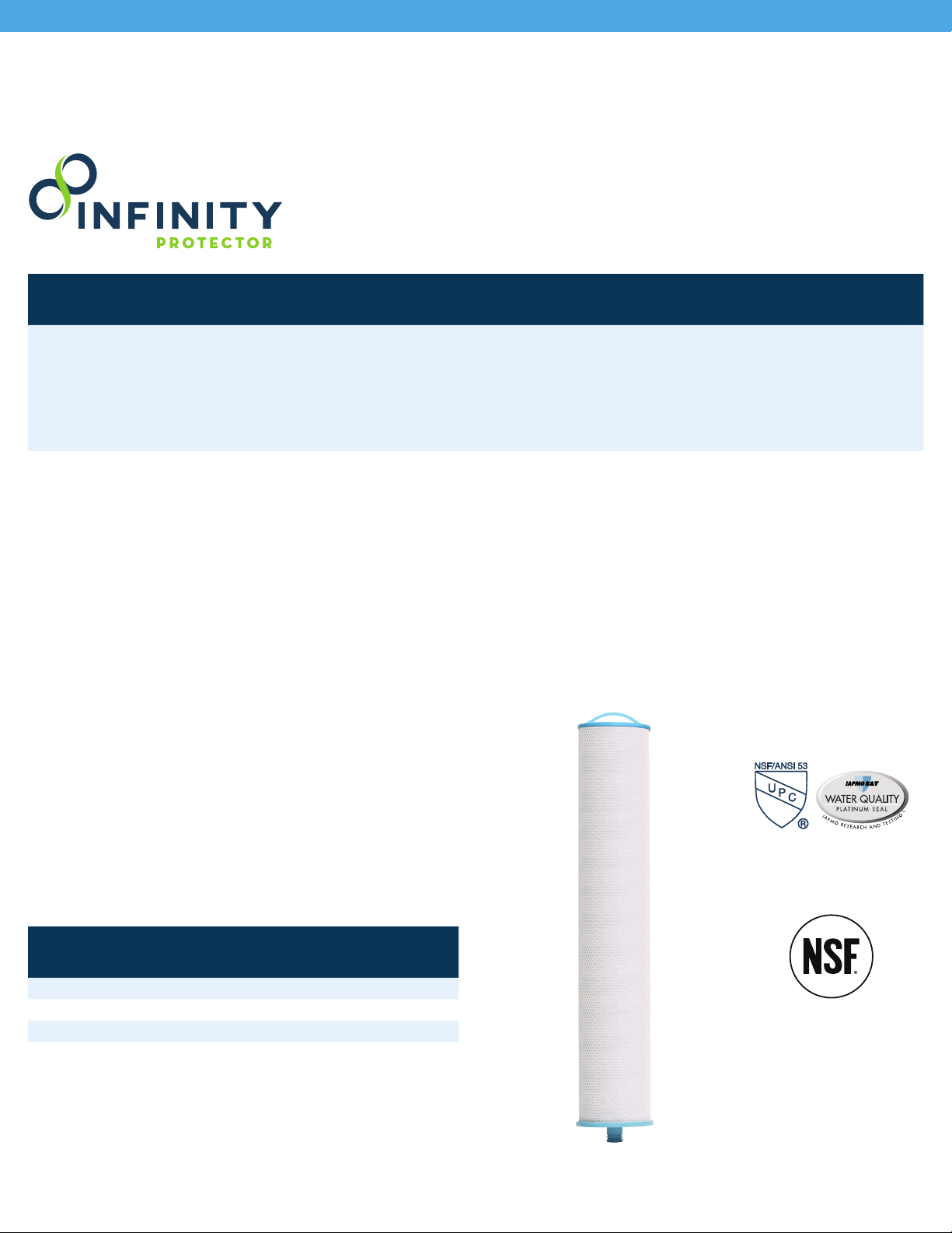
INFINITY PROTECTOR
PRODUCT FEATURES & PRECAUTIONS
Certied Safety &
Performance to Reduce:
Lead
PFAS (PFOA/PFOS)
Cysts (Giardia & Crypto)
PRECAUTIONS
Filter is only to be used with cold water.
The contaminants or other substances removed or reduced by this water filter are not necessarily in
all users’ water.
Testing was performed under standard laboratory conditions, actual performance may vary.
System has been designed and tested to be used on municipally treated water sources. Do not use with
water that is microbiologically unsafe or of unknown water quality without adequate disinfection before
or after the system.
Filter usage must comply with all state and local laws and regulations.
Manufactured from NSF/ANSI standard 61 and California Prop 65 Compliant certified coconut shell carbon
and raw materials.
65
65
65
65
65
65
Also Addresses*:
Chlorine & Chloramines
Pharmaceuticals&Contaminants
VolatileOrganicCompounds(VOCs)
Sediment
*Internal data only. Level of reduction has not been veried by IAPMO R&T
MODEL: INF-PRO1
INSTALLATION OF INFINITY
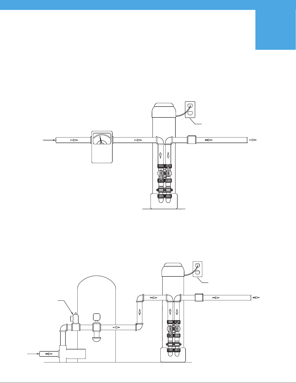
WHERE TO INSTALL 1
CITY WATER
INLET WATER
METER
SERVICE
GROUNDED
&
UNSWITCHED
115-
VOLT
OUTLET
SERVICE
GROUNDED
&
UNSWITCHED
115-
VOLT
OUTLET
WELL
INLET
RELIEF VALVE
MUST BE
INSTALLED
PRESSURE
TANK
PUMP
WELL WATER
CITY WATER
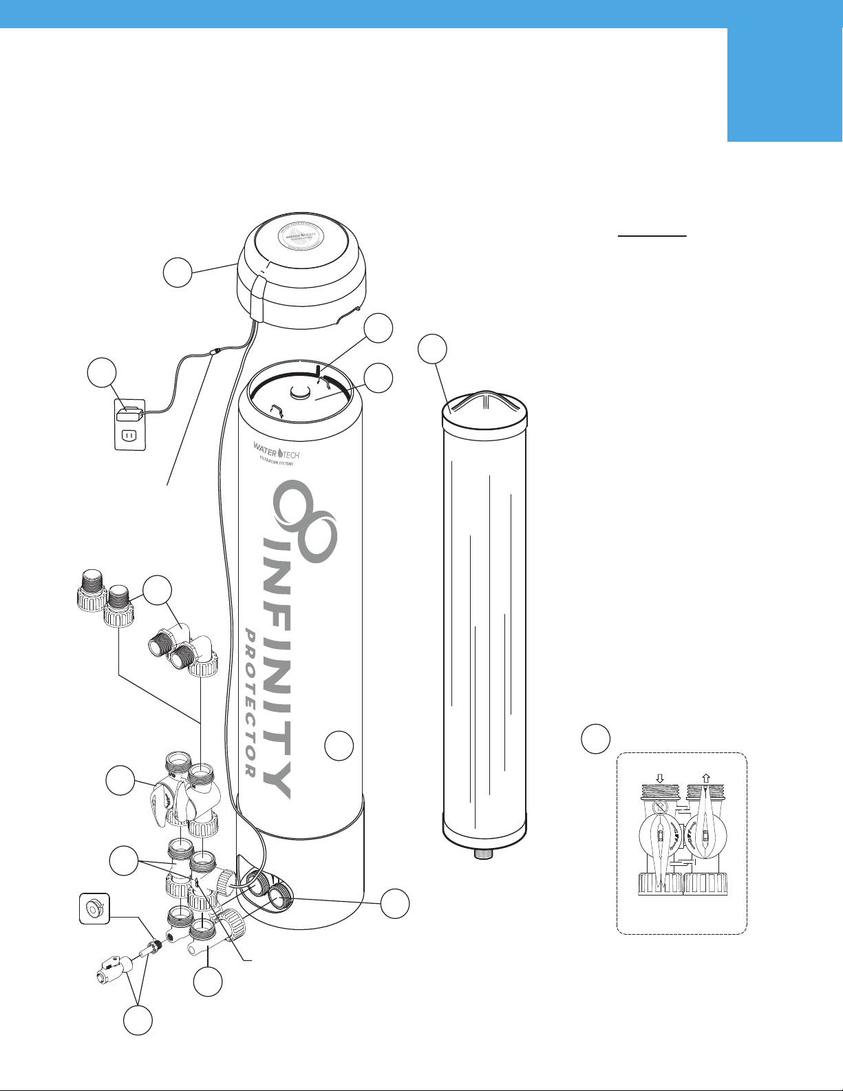
INSTALLATION OF INFINITY
PRODUCTS & PARTS DIAGRAM
Flow Meter should be
placed on the Outlet
Side. Note the flow
direction arrow on the
meter body.
1
3
2
4
7
TEFLON TAPE THREADS
Do Not Overtighten
9
5
6
PARTS
1. Filter housing
(10-00-001)
2. Bottom Inlet/Outlet cap assembly
(10-00-002)
3. Vertical elbow
(10-00-003)
4. 3/8” PEX Drain valve assembly
with shut-off
(10-00-004)
5. Flow Meter Assembly
(10-00-005)
6. Bypass manifold
(10-00-006)
7. Straight or 90-degree Angled In/Out
1” MNPT plumbing connectors
(10-00-007)
8. Power Supply
(10-00-008)
9. Umbrella Cap with PCB assembly
and battery backup
(10-00-009)
10. Top Cap
(10-00-010)
11. Retaining Ring
(10-00-011)
12. Replacement Filter
(INF-PRO1-FX)
DRAIN VALVE
Bypass Orientation
INLET OUTLET
Flow direction arrows on bypass are
incorrect for this filter application.
Plumb unit opposite of arrows.
6
Connection to
Power Supply
810
11
The system and installation must comply with state and local laws and regulations.
Plumbing the filtration system assembly: The inlet and outlet of the filtration housing are
1” Threaded MNPT connections.
**No Use of Extra lubricants, unapproved sealants, and use of tools. Use of tools other
than hand tighten only parts, voids warranty.
Please allow 3 feet of open space above the system for replacement cartridges.
System to be supplied only with cold water.
3-AAA batteries not included.
Meter assembly preset to 100,000 gallons
12
2
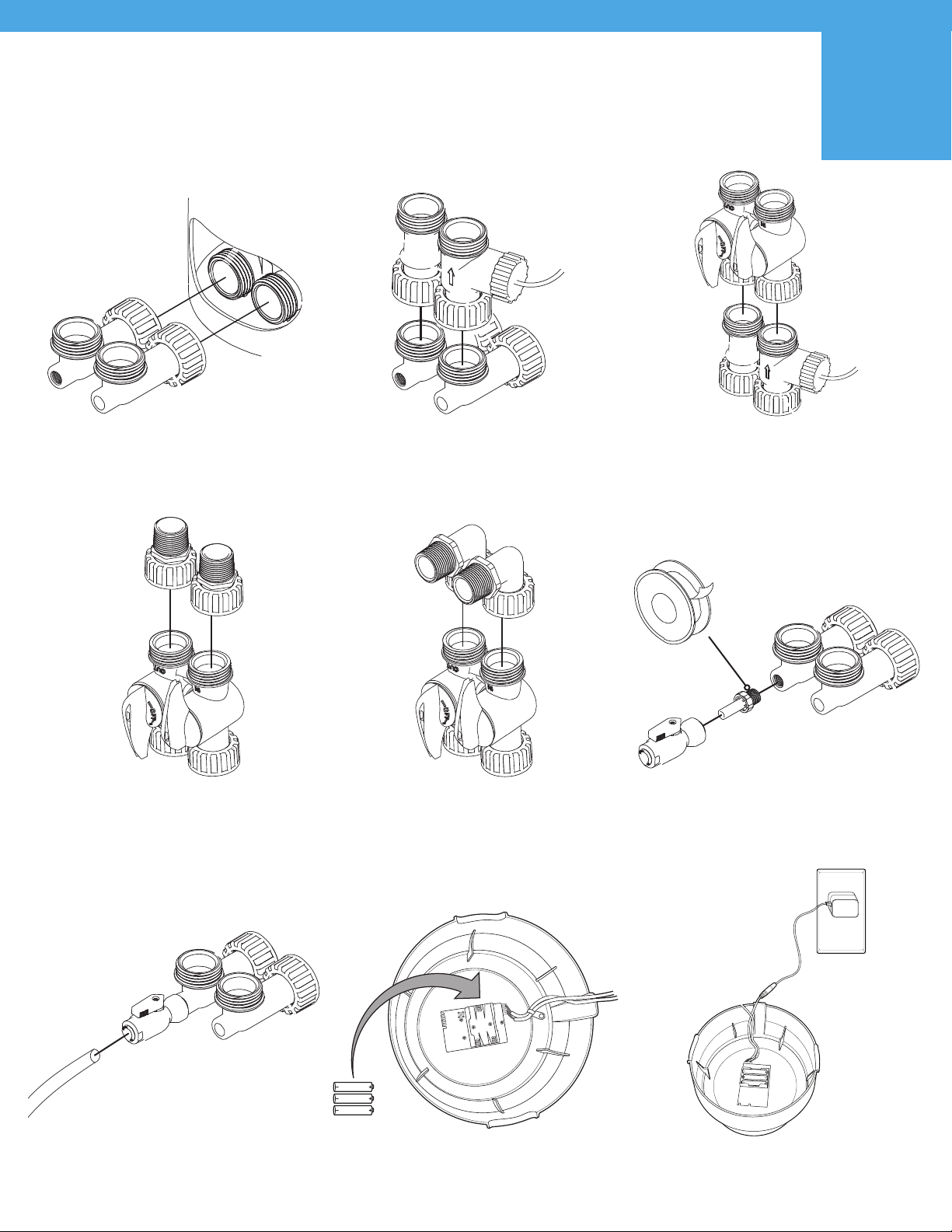
INSTALLATION OF INFINITY
SIMPLE ASSEMBLY INSTRUCTIONS
NOTE: Additional parts box inside filter housing tank.
STEP 1
Connect #3 to #2 on the bottom of the Filter Housing #1.
HAND TIGHTEN ONLY
STEP 4OPTION A
Use #7 (Straight In/Out 1” MNPT) for
connecting your plumbing to the system.
HAND TIGHTEN ONLY
STEP 6
Connect 3/8” PEX Plumbing to drain.
NOT PROVIDED
STEP 2
Connect #5 to #3; Flow Meter Assembly
should be placed on the Outlet Side.
(Note the flow direction arrow on the meter body)
HAND TIGHTEN ONLY
STEP 4OPTION B
Use #7 (90-degree Angled In/Out 1” MNPT) for
connecting your plumbing to the system.
HAND TIGHTEN ONLY
STEP 7
Install 3-AAA batteries on Umbrella Cap.
STEP 3
Connect #6 Bypass to #5
HAND TIGHTEN ONLY
STEP 5
Install part #4 into #3 using the threaded
connection & Teflon®tape.
HAND TIGHTEN ONLY
STEP 8
Connect Power Supply to Umbrella Cap cord & to wall.
1.5V AAA
1.5V AAA
1.5V AAA
TEFLON TAPE THREADS
Do Not Overtighten
DRAIN VALVE
1.5V AAA
1.5V AAA
1.5V AAA
2 3
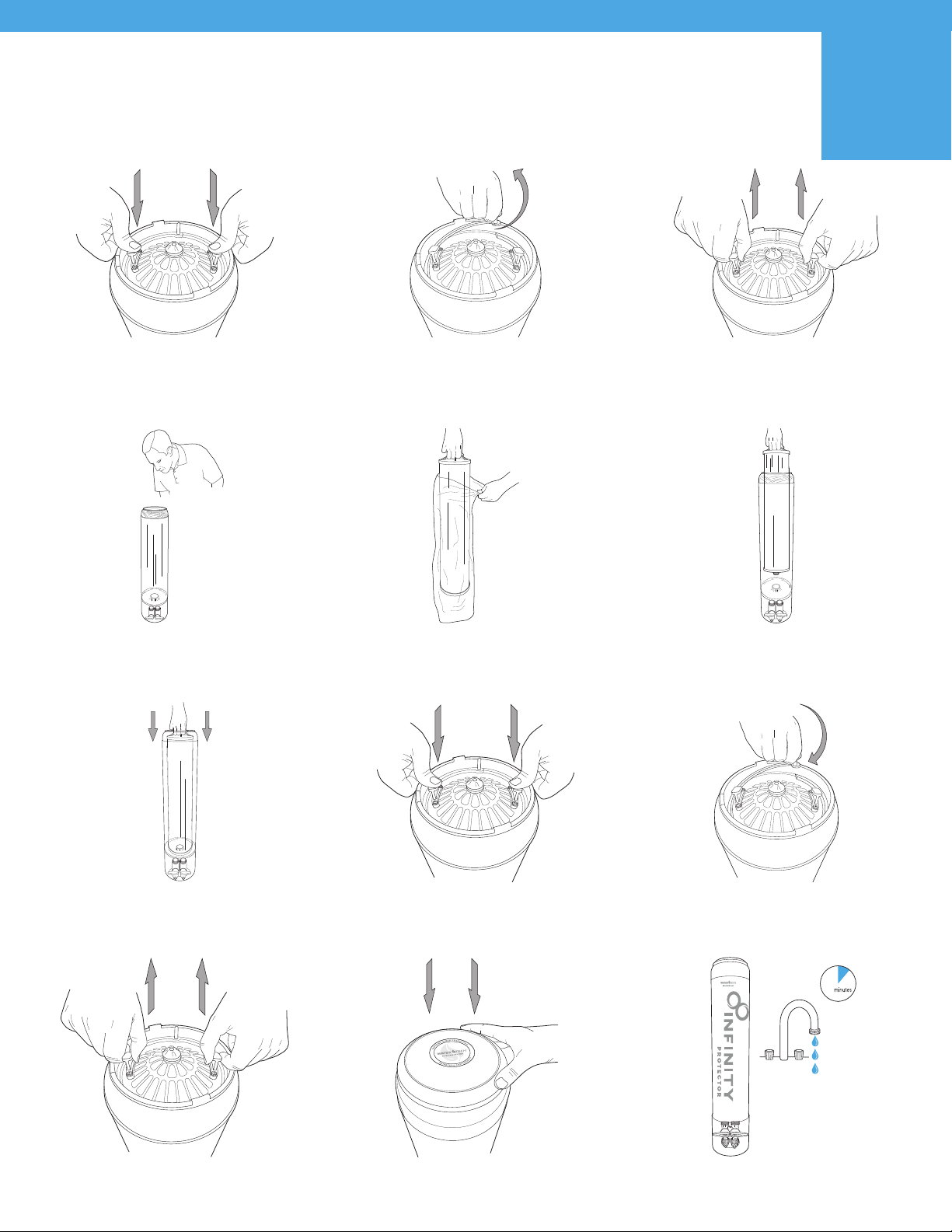
INSTALLATION OF INFINITY
FILTER CARTRIDGE INSTALLATION
STEP 1
Push down the top cap with both hands.
STEP 4
Look down into the tank assembly, and you should see
a small opening centered in the bottom of the tank.
STEP 7
Press down on the filter cartridge so that the double O-ring
seal moves into place within the bottom, center opening.
STEP 10
Pull up on the Top Cap to seat o-rings.
STEP 2
Remove the retaining ring by carefully grasping the handle
and pulling inward, then upward. The retaining ring should
slide completely out of the groove.
STEP 5
Remove packaging from filter cartridge, then place the filter
cartridge into the tank with the double O-ring facing down.
STEP 8
Reposition the Top Cap into its original location.
STEP 11
Place Umbrella Cap on top of system.
STEP 3
Remove the Top Cap from the housing assembly by pulling
the cap out of the top of the tank, by lifting up on the top
handles. Place removed Top Cap on a clean and dry surface,
free of debris, so no contamination of the o-ring occurs.
STEP 6
Position the cartridge so that it is aligned
with the bottom, center opening.
STEP 9
Reattach the top tank Snap Ring.
STEP 12
Run water through system for 10 minutes before use.
10
4
FILTER CARTRIDGE
REPLACEMENT
4 1
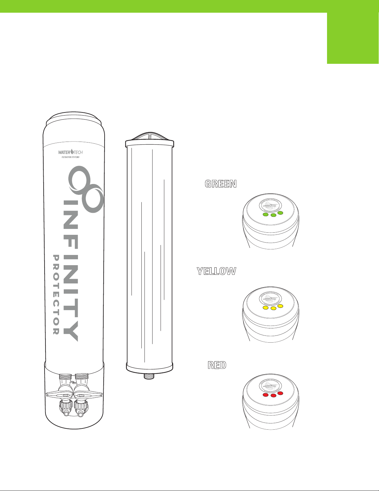
Easy to understand LED Filter
Replacement Notifications
The Real-time Dynamic LED System on the Umbrella Cap
monitors water and ow rate and provides a visual
color-coded notication, letting you know when the lter has
reached certied capacity level at 100,000 gallons and to
Replace the Filter.
GREEN LIGHTS = Filter Good
RED LIGHTS = Change Now
YELLOW LIGHTS = Change Soon
10% Filter Life Remaining
Filter Replacement
Part Number:
INF-PRO-FX1
1.5V AAA
1.5V AAA
1.5V AAA
1
1.5V AAA
1.5V AAA
1.5V AAA
2
FILTER CARTRIDGE
REPLACEMENT
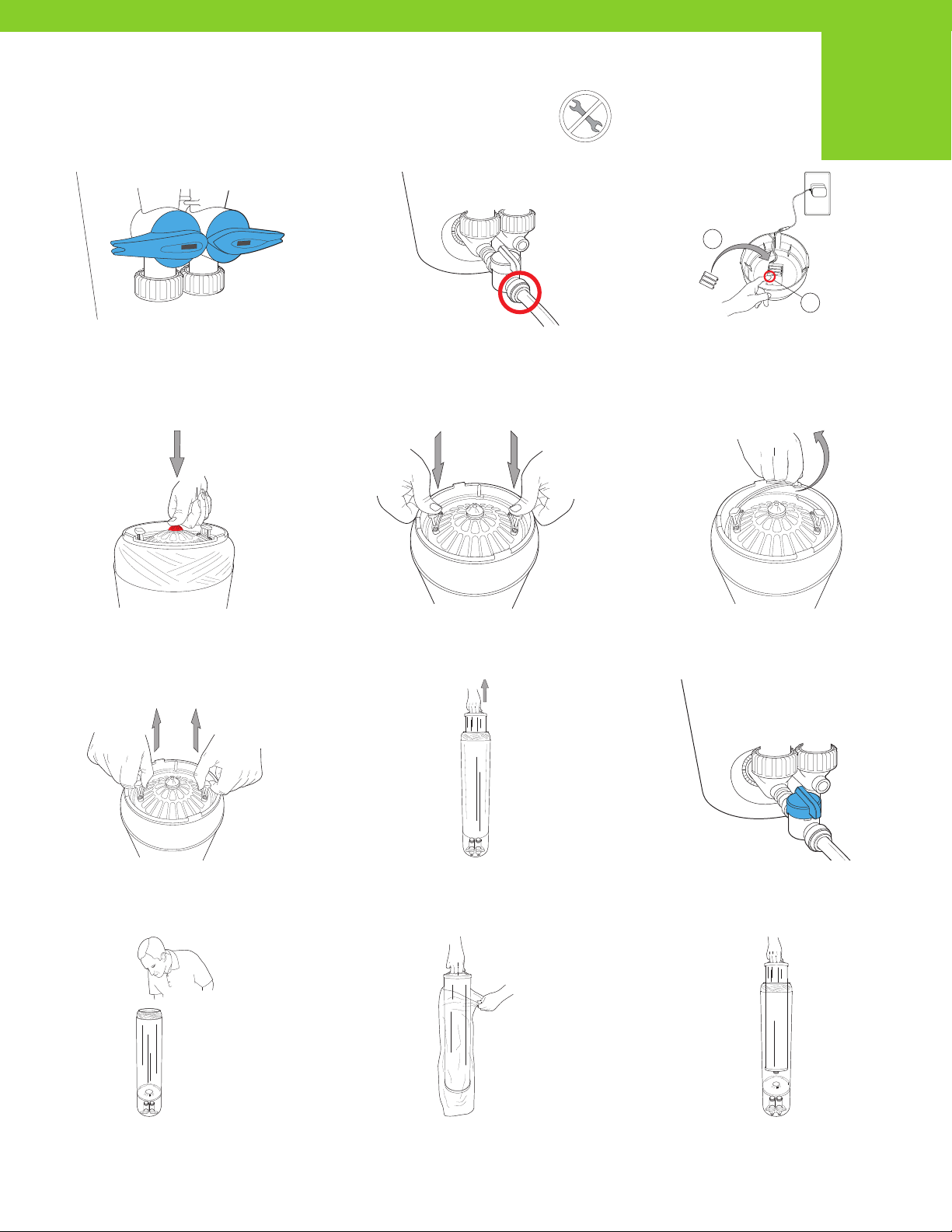
STEP 1
Turn off the water supply to the system by shutting off the
inlet and outlet valves on the bypass.
STEP 4
Depressurize the system by pushing down on the red
depressurization button on the top cap of the system.
Keep the button pushed down until all the air or water
pressure is completely released.
STEP 7
Remove the top cap of the system by lifting
up on the top handles.
STEP 10
Look down into the tank assembly, and you should see
a small opening centered in the bottom of the tank.
STEP 2
Install a 3/8” PEX tubing hose to the provided
John Guest®fitting and shut-off that connects to the
inlet side of the filtration system. Run the hose to a
floor drain or bucket, and use to drain sediment or
to aid in filter removal during change-out.
STEP 5
Push down the top cap with both hands to unseat the
retaining ring.
STEP 8
Remove old filter and discard.
STEP 11
Remove packaging from the new filter cartridge and place
into the tank with the double O-ring facing down.
STEP 3
1. Remove Umbrella Cap on the top of the vessel. Replace
the 3-AAA batteries with new batteries. 2. Push and hold
the reset button on the circuit board for 3 seconds to
reset the totalizer. When the totalizer is reset the LED lights
will flash green 3 times to confirm that it is reset.
STEP 6
Remove the retaining ring by carefully grasping the handle
and pulling inward, then upward. The retaining ring should
slide completely out of the groove.
STEP 9
Open the John Guest®fitting shut-off, and
flush out the bottom.
STEP 12
Position the filter cartridge so that it is aligned
with the bottom, center opening.
NO TOOLS
REQUIRED 2
FILTER CARTRIDGE
REPLACEMENT
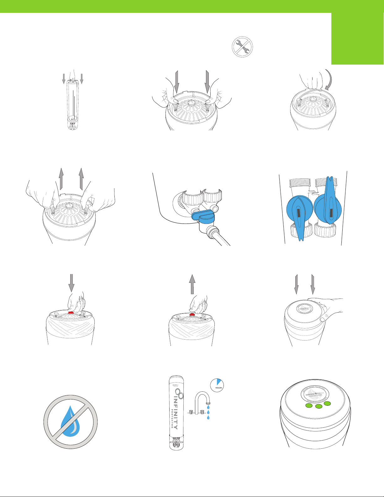
STEP 13
Press down on the filter cartridge so that the double O-ring
seal moves into place within the bottom, center opening.
STEP 16
Pull up on the Top Cap to seat o-rings.
STEP 19
Relieve the system of air in the tank as the system fills with
water, by pushing down on the red depressurization button
on the top cap of the system. Keep the button pushed down
until all the air pressure is completely released, and water
comes out of the red depressurization button.
STEP 22
Check for leaks.
STEP 14
Reposition the Top Cap into its original location.
STEP 17
(If completed Step 2, then…) Close the
John Guest®fitting and shut-off.
STEP 20
Release the red depressurization button.
STEP 23
Run water through system for 10 minutes before use.
STEP 15
Reattach the top tank Snap Ring.
STEP 18
Turn the water supply on, opening the inlet
and outlet valves on the bypass.
STEP 21
Replace the Umbrella cap to the top of the system.
STEP 24
During flush, confirm green LED lights are flashing
with flowing water. If lights are not flashing green,
go back to step 3.
10
NO TOOLS
REQUIRED 32
CERTIFIED WATER FILTER SYSTEM
IMPORTANT
DO NOT USE extra lubricants, unapproved sealants and tools to tighten hand tightened
only parts. Use of tools other than hand tighten only parts voids warranty. Testing was
performed under standard laboratory conditions; actual performance may vary. Flush
the system and change the lter as suggested. The contaminants or other substances
removed or reduced by this water lter are not necessarily in all users’ water.
PERFORMANCE
Performance claims are based on independent lab results and manufacturer’s internal
test data*. Actual performance is dependent on inuent water quality, ow rates,
system design and applications. Your results may vary. Performance claims are based
on a complete system, including a lter, housing, and connection to a pressurized
water source. This lter must be operated according to the system’s specications
in order to deliver the claimed performance. It is essential to follow operational,
maintenance, and lter replacement requirements, as directed for each application, for
this lter and system to perform correctly. Read the Manufacturer’s Performance Data
Sheet accompanying the system and change the lter as suggested. The contaminants
or other substances removed or reduced by this water lter are not necessarily in all
users’ water.
This system has been tested for the reduction of the substances listed below. The
concentration of the indicated substances in water entering the system was reduced
to a concentration less than equal to the permissible limit for water leaving the system,
as specied in NSF/ANSI 53. Minimum substance reductions are as follows:
SUBSTANCE INFLUENT CHALLENGE
CONCENTRATION (MG/L)
MAXIMUM PERMISSIBLE
PRODUCT WATER
CONCENTRATION (MG/L)
NSF/ANSI
STANDARD
Lead 0.15 +/- 10% 0.01 53
Cyst minimum 50,000/L 99.95% 53
PFOA/PFOS 1.5 +/- 10% 0.07 53
v
NAME AND
PART NUMBER
SIZE &
MICRON
RATING
RATED CAPACITY & FLOW RATE PEAK FLOW &
% REDUCTION OF LEAD
CHLORINE/CHLORAMINE
TASTE AND ODOR REDUCTION CAPACITY (*)
PRESSURE DROP
SPEC
Infinity Protector
INF-PRO1 8” x 40” 0.5
Lead Reduction and PFOA/PFOS
100,000 gallons @ 4.51 GPM (378,541
Liters @ 17.1 lpm)
@ 99.62% lead reduction
@ 97.9% PFOA/PFOS reduction
8 GPM (30.2lpm) @
99.62% reduction
(*) >88,000 gallons at 8 GPM
(333,116 Liters @ 30.2lpm)
>300,000 gallons @ 15 GPM
(1,135,533 Liters @ 56.8 lpm) with greater than
90% reduction, estimated capacity using 2ppm of
free chlorine.
>150,000 gallons @ 8 GPM
(567,812 Liters @ 30.3 lpm) with greater
than 85% reduction, estmated using 3ppm
of chloramine.
9 psid
@ 4.51 GPM
REPLACEMENT CARTRIDGE FILTERS ARE LISTED AS Infinity Protector 0.5 Micron High Capacity Carbon Block // PART NUMBER: INF-PRO1-FX
*Claims are not performance tested by IAPMO or NSF. Performance claims are based on independent laboratory and manufacturer’s internal test data.
Actual performance is dependent on influent water quality, flow rates, system design and application. Results may vary.
This system is certified by IAPMO R&T against
NSF/ANSI Standards 53 (also CSA B483.1)
for the reduction of claims specified on the
performance data sheet.
This pressure vessel is tested and certified
by NSF International against NSF/ANSI
Standard 44 and 61 for materials and
structural integrity requirements
Electrical Requirements: Grounded & Unswitched 115 V outlet and 3-AAA Batteries
Filter Replacement Operating Instructions: New cartridges must be ushed for a
minimum of 10 minutes prior to use. System and installation to comply with state and
local laws and regulations. Do not use with water that is microbiologically unsafe or
unknown quality without adequate disinfection before or after the system. Systems
certied for cyst reduction may be used on disinfected waters that may contain
lterable cysts. Manufactured from NSF/ANSI standard 61 and California Prop 65
Compliant certied coconut shell carbon and raw materials.
SPECIFICATIONS
Indice
Altri manuali WaterTech Sistema di filtraggio dell'acqua

WaterTech
WaterTech Volt Series Manuale utente

WaterTech
WaterTech VOLT FX-4Li Manuale utente

WaterTech
WaterTech MC-1 Manuale utente

WaterTech
WaterTech SP Series Manuale utente

WaterTech
WaterTech INF-SEN1 Manuale utente

WaterTech
WaterTech Reionator Pro Ultra RXU13 Manuale utente

WaterTech
WaterTech Reionator Pro RX10 Manuale utente

WaterTech
WaterTech CONGO Manuale utente

WaterTech
WaterTech SORBMAXPRO Manuale utente

WaterTech
WaterTech PURE PRO QC Guida all'installazione


