
watt box WB-800ICH1U-IPVM-8 Manuale utente

WB-800ICH1U-IPVM-8
Quick Start Guide

2
Important Safety Instructions
Read and observe the following safety points at all times.
Notice
For indoor user only. Internal components are not sealed form the environment. The device can only be used
in a fixed location such as a telecommunication centre, or a dedicated computer room. When you install
the device, ensure that the protective earthing connection of the socket-outlet is verified by a skilled person.
Suitable for installation in Information Technology Rooms in accordance with Article 645 of the National
Electrical Code and NFPA 75.
Only use brackets/attachments/accessories specified by the manufacturer.
Do not place the device in an unstable position where it might fail and cause injuries. This equipment is not
suitable for use in locations where children are likely to be present.
Do not cover this device with a cloth. Do not install it on a carpet or rug.
3
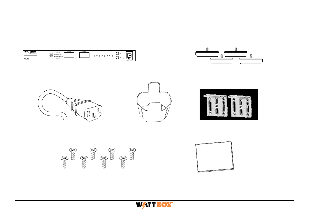
Package Contents
(1) WB-800ICH1U-IPVM-8 (4) Screw-in feet and screws
(1) Removable, region-specific
power cord (in over-pack box, not
PDU carton)
(1) IEC sleeve (2) Rack mounting brackets
(8) Mounting bracket screws
(M3 x 6 mm)
(1) Quick Start Guide

4
Rear Panel
A. Power Inlet: For a 3-prong IEC power cord.
B. Circuit breaker: 10A resettable breaker that trips when over amperage conditions occur. Press to reset.
C. Bonding Point: Post for bonding equipment.
D. Controllable outlets 1-8: All outlets are filtered against EMI/RF and individually switchable (IP controlled).
E. Power indicators for outlets 1-8: Illuminates when power is on (x8 – 1 for each outlet).
F. Reset button: Press and release to restart the network card, press and hold five seconds to reset network settings,
and press and hold 10 seconds to restore to factory defaults.
G. Safe Voltage button: Toggles the Safe Voltage feature on and o. When enabled, Safe Voltage turns o outlets to
protect connected equipment from out-of-range input voltage.
H. UPS Link: For future use to connect a WattBox OvrC-enabled UPS.
I. ACC port: Accessory port for future use.
J. Network port: Connect to the local area network (LAN) for IP control and monitoring.
240VAC 60Hz
A B D E F G
H I
J
C

5
Front Panel
A. AC Power button: Press and hold for 3 seconds to manually toggle the outlets on or o. Outlets configured as
Disabled or Reset Only are not aected.
B. LED indicators: See the status of the internet, Safe Voltage, surge protection, and whether the unit is properly
grounded. Refer to “LED Operation” on page 8.
C. Input Voltage display: Displays the input voltage being supplied from the outlet.
D. Output Current display: Displays current draw in amps (A). This figure can be an aggregate of the combined
outlets or a single outlet.
E. Outlet power indicator: Illuminates when the corresponding controlled outlet number is powered.
F. Button 1: Sequences through outlets 1 through 8 (left to right) displaying the Current for the specified outlet.
Aggregate of all outlets display when clicking past outlet 8. This button is also used to reset individual outlets. See
“How to Manually Reset Individual Outlets from the Faceplate” on page 6.
G. Button 2: Sequences through outlets 8 through 1 (right to left) displaying the Current for the specified outlet.
Aggregate of all outlets display when clicking past outlet 8. This button is also used to reset individual outlets. See
“How to Manually Reset Individual Outlets from the Faceplate” on page 6.
H. Accessory Outlet (Unprotected): Always-on, front-facing outlet for service use. Not IP controllable. A solid blue
LED indicates the outlet has power and is working.
ABD E F GH
C

6
How to Sequence Through Individual Outlets
• Tap B1 to sequence through outlets 1-8 (moving left to right).
• Tap B2 to sequence through outlets 8-1 (moving right to left).
As you sequence through the outlets, the corresponding outlet LED flashes to indicate which outlet number
you are on. The displays show the corresponding Current for the outlet specified.
Note: The LED light flashes on the specified outlet for 5 minutes, during this time the display windows
show the Current for the selected outlet. Once the 5 minutes has expired, the WattBox defaults
back to displaying the aggregate total of the entire unit, and all LEDs default back to being
illuminated.
How to Manually Reset Individual Outlets from the Faceplate
1. Tap B1 or B2 to sequence through the outlets.
2. With the outlet number that needs to be reset flashing, press and hold B1 or B2 for 3 seconds. The
Current display shows a rotating 0as the outlet resets.

7
How to Manually Reset All Outlets from the Faceplate
To reset all of the outlets, press and hold B1 and B2 at the same time for 3 seconds. The Current display shows
a rotating 0 as the outlets reset.
Note: The reset follows the Power-On delay set in OvrC. Outlets designed as Disabled in OvrC do not
reset.

8
LED Operation
Note: LEDs on the front and back of the WattBox function identically.
Internet
Blue (Solid) All host sites/IP addresses are communicating with the WattBox.
Blue (Flashing) Host ping partial fail. At least one host site/IP address ping is communi-
cating with the WattBox.
Red (Solid) None of the host sites/IP addresses are communicating with the WattBox.
Safe
Voltage
Blue (Solid) Safe Voltage is enabled and current incoming AC voltage is safe for
operation. All outlets are receiving power.
Blue (Slow Blink) Safe Voltage is enabled, but the incoming voltage is not safe.
O Safe Voltage is disabled.
Surge
Protected
Blue (Solid) The WattBox is powered on and outlets are protected.
O The WattBox is not powered on, or the MOVs have opened, removing
power from the outlets.
Grounded
Blue (Solid) Incoming AC outlet is grounded.
O Incoming AC outlet is not grounded and requires inspection by an
electrician.

9
Positioning Options
The WB-800ICH1U-IPVM-8 can be mounted in a rack or placed in a cabinet.
Rack Mounting
Attach mounting brackets to the WattBox using the supplied hardware, then install the WattBox into the rack
using standard rack screws (not included).

10
Cabinet Placement
Attach supplied feet to the bottom of the WattBox for cabinet placement.
Indice
Altri manuali watt box Accessori


