
Weidmüller Klippon TB MH Manuale di istruzioni
R.T.Nr. 1194340000/02/08.11
Assembly guidelines – empty enclosures 3
Montagerichtlinien – Leergehäuse 11
Consignes de montage - coffrets vides 19
Instrucciones de montaje de armarios vacíos
27
Istruzioni di montaggio – custodie vuote 35
Руководство по монтажу – пустые корпуса 43
Klippon® TB MH
II 2 G Ex e IIC Gb
II 2 D Ex tb IIIC Db IP66/67
IEC 60079-0:2007; EN 60079-0:2009
IEC 60079-7:2006; EN 60079-7: 2007
IEC 60079-31:2008; EN 60079-31:2009
IECEx KEM 10.0015U
KEMA 10ATEX0046U


3
Empty enclosures characteristics
Material: Stainless Steel 316L / 1.4404; 304 / 1.4301;
Mild steel painted
Temperature: -60°C…. +135°C
IP-Rating IP 66/67 (IP 67 max .Temp.: 105°C)
ATEX use: The complete assembled enclosure must be certied
by a recognised, notied body and in line with the ATEX
directives!
4
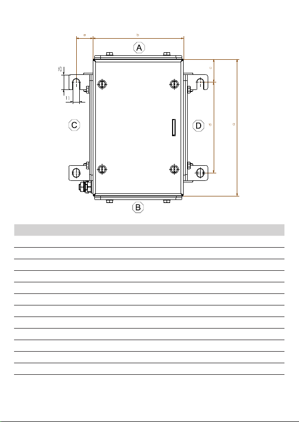
Mounting the Enclosure
a (mm) b (mm) c (mm) d (mm) e (mm)
KTB xx 2215xx 292 152 38.5 215 28*
KTB xx 2626xx 260 260 45 170 28*
KTB xx 3030xx 306 306 51.5 203 28*
KTB xx 3526xx 350 260 51.5 247 28*
KTB xx 4030xx 400 300 76.5 247 28*
KTB xx 4538xx 458 382 76.5 305 28*
KTB xx 4848xx 480 480 76.5 327 28*
KTB xx 5535xx 550 350 100 350 28*
KTB xx 6245xx 620 450 100 420 28*
KTB xx 7650xx 762 508 127 508 28*
KTB xx 9161xx 914 610 177.5 559 28*
KTB xx 9874xx 980 740 177.5 625 28*
* subtract 15 mm if the enclosure is not tted with gland plates
on side C or D
5
Opening of the Enclosure
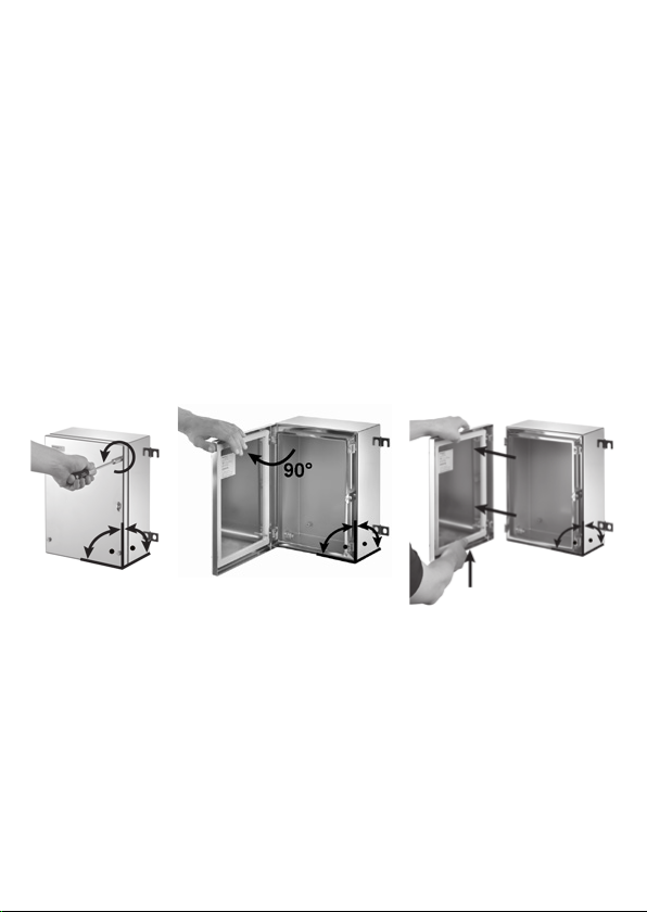
Place enclosure in a vertical upright position. Loosen the lid cover xings
screws with a suitable tool (refer to diagram 1 below). After loosening the
covers screws, the lid can be opened up to approximately 130°.
Removing the lid
The lid should be removed by loosening the cover xing screws and any
attached lid bonding cable with a suitable tool. After loosening the xing
screws the cover lid must be opened to a 90° position (refer to diagram 2
below). With the lid in this position, lift the lid slightly and slide to the outside
to release (refer to diagram 3 below). In this way you are able to x the lid
to either the left or the right hand side of the enclosure (multi hinge version
only). If the lid position is to be xed to another side, it is also necessary to
reposition the padlock lug to the opposite side. Do not remove the captive
element of the screws!
1 2 3
Removing gland plates
If gland plates are to be used remove them by loosening the gland plate
screws with a suitable tool. Afterwards the plates can be detached.
Closing the enclosure
Ensure that all lid, gland plate, earth stud screws are fully tightened in a
crosswise manor after installation.
Tightening Values
Lid & Gland plates (when present) 2.5 Nm
M10 earth stud (out-/inside) 15.0 Nm
M6 earth stud inside 6.0 Nm
6
Fitting Cable Glands
Drilling Information
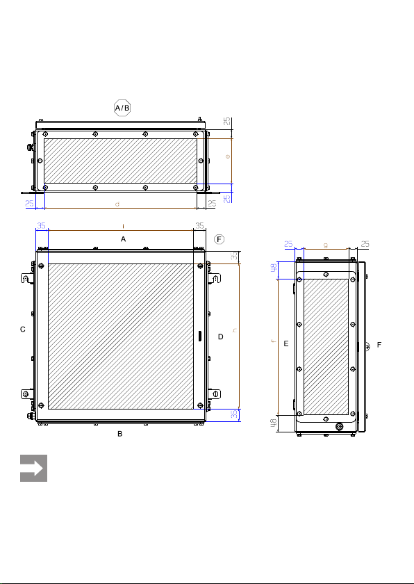
The permissible areas for drilling are indicated in the table below. In each
case if the required ingress protection rating (IP) is stated on the certica-
tion label (ATEX or IECEx), the stated IP rating must be maintained.
The permissible drilling area (the shaded area) in the drawing
above is the same for an enclosure that is supplied either with or
without a gland plate.
For enclosures that are larger than size KTB MH 765015, the drill-
ing areas on sides C and D are based on two separate gland zones.
The separation area is 60 mm. Note: Whether gland plates are tted
or not, this separation area has to be taken into account!

7
Drilling Information (Gland Plate Only)
The available area of the drilling zone for each individual gland plate is de-
tailed below:
drilling zone gland placement diameter drilling diameter
The allowed drilling zone is 22 mm in distance from the outer edges
of each plate.
Within the indicated drilling zone, various cable entries can be drilled based
on the following table and conditions:
Drilling Diameter +0.2 mm
-0.0 mm
Gland Placement Diameter
(mm)
M16 16.0 22.4
M20 20.0 28.0
M25 25.0 35.0
M32 32.0 44.8
M40 40.0 56.0
M50 50.0 70.0
M63 63.0 88.2
M75 75.0 105.0

8
Drilling Diameter +0.2 mm
-0.0 mm
Gland Placement Diameter
(mm)
PG7 13.0 18.2
PG9 15.0 21.0
PG11 19.1 26.7
PG13,5 20.9 29.3
PG16 23.0 32.2
PG21 28.8 40.3
PG29 37.5 52.5
PG36 47.5 66.5
PG42 54.5 76.3
PG48 59.8 83.7
• Drill holes using the specied drilling diameters and gland placement di-
ameters. (See table above)
• When using gland plates, only 20% of the material may be removed.
(Note: For guidance, ensure a minimum distance of at least 15 mm be-
tween the individual gland placement diameters.)
• When drilling directly into the enclosure (lid or body) only 10% of the ma-
terial from each individual side may be removed.
(Note: For guidance, ensure a minimum distance of at least 30 mm be-
tween the individual gland placement diameters.)
• If locknuts are to be used, it is essential to decrease the drilling area by
the additional area of the locknut.
• When drilling, avoid ANY deformation, overheating of the enclosure or
gland plate. Ensure that the hole ( the cable gland) is sealed afterwards
according to the relevant ingress protection rating (IP).
9
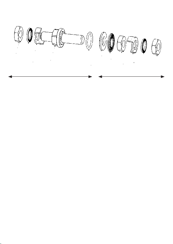
Internal/External Earth Stud Assembly
The drawing below provides a prole of the earth stud.
G F E A C B D G E F G
outside enclosure inside enclosure
A 1 x earth bolt M10
B 1 x washer Ø 20 mm t = 2 mm
C 1 x silicone O- Ring
D 1 x washer (lug) Ø 20 mm
E 2 x clamping bracket
F 2 x washer (lug) Ø 15 mm
G 3 x nut M10 Torque: 15 Nm
Lid Earth Screw Assembly
Attach the cable lug to the earth screw followed by the spring washer and
tighten the complete assembly with a nut (with a torque of 6.0 Nm).
10
Inspection, Maintenance and Repairs
WARNING
Disconnect power supply before installing or servicing these
enclosures.
Ensure that only authorized and trained personnel perform repairs and
maintenance work.
For an Ex-certied enclosure the training has included the instruction of the
various types of protection and installation practices, the relevant rules and
regulations.
Inspection / Maintenance
After opening an enclosure, a visual inspection of the lid and gland plate
gasket must be performed to ensure no foreign objects may interfere with
the enclosure sealing function. A visual inspection of the apparatus shall be
carried out in a method appropriate to the installation environment.
Inspection should include verication that all lid and gland plate screws
(where tted) are secured with the proper torque. Checks should also in-
clude that there is no ingress (dust or liquid) inside the enclosure and that
all cable glands and main earth connections are in good condition.
Cleaning
The enclosure should be cleaned with a damp cloth. Do not clean the enclo-
sure with hydrocarbonbased cleaning compounds!
Repair
Only parts authorized by the manufacturer (such as mounting plates, earth
studs and gland plates) may be used for replacements and modications.
Indice
Lingue:
Altri manuali Weidmüller Allegato


