WEISS Vesta Manuale utente
Weiss Engineering Ltd.
Florastrasse 42, 8610 Uster, Switzerland
www.weiss-highend.co
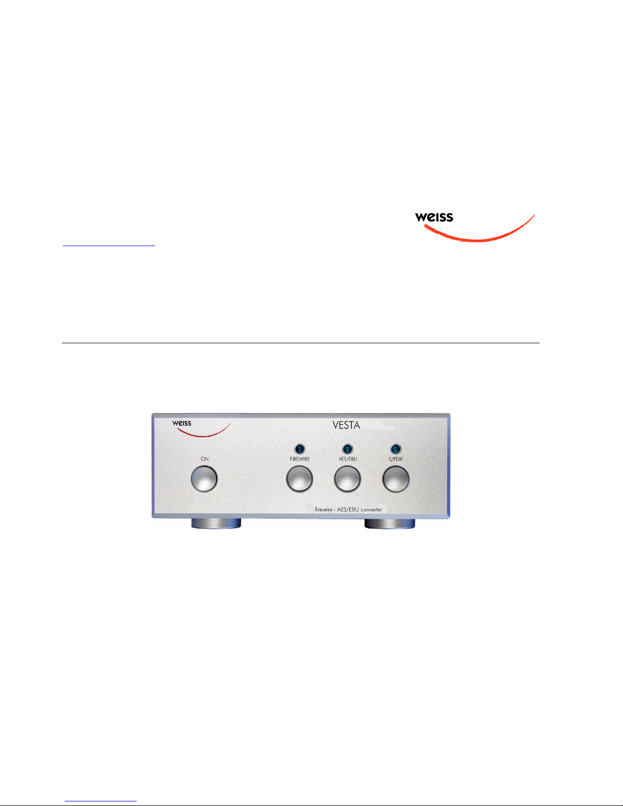
VESTA
OWNERS MANUAL
OWNERS MANUAL FOR WEISS VESTA FIREWIRE INTERFACE
Page: 2Date: 10/08 /dw
INTRODUCTION
D
ear
C
usto er
Congratulations on your purchase of the VESTA Firewire Interface and welco e to the fa ily of
Weiss equip ent owners!
The VESTA is the result of an intensive research and develop ent process.
On the following pages I will introduce you to our views on high quality audio processing. These
include funda ental digital and analog audio concepts and the VESTA interface.
I wish you a long-lasting relationship with your VESTA. She won’t let you down.
Yours sincerely,
Daniel Weiss
President, Weiss Engineering Ltd.

OWNERS MANUAL FOR WEISS VESTA FIREWIRE INTERFACE
Page: 3Date: 10/08 /dw
TABLE OF CONTENTS
4 A short history of Weiss Engineering
5 Our ission and product philosophy
6 Advanced digital and analog audio concepts explained
6 Jitter Suppression, Clocking
9 Upsa pling, Oversa pling and Sa pling Rate Conversion in General
11 Reconstruction Filters
12 Analog Output Stages
12 Dithering
14 Firewire vs USB
15 The VESTA Firewire Interface
15 Features
18 Operation / Installation
24 Technical Data
26 Contact

OWNERS MANUAL FOR WEISS VESTA FIREWIRE INTERFACE
Page: 4Date: 10/08 /dw
A SHORT HISTORY OF WEISS ENGINEERING
After studying electrical engineering, Daniel Weiss joined the Willi Studer (Studer - Revox)
co pany in Switzerland. His work included the design of a sa pling frequency converter and of
digital signal processing electronics for digital audio recorders.
In 1985, Mr. Weiss founded the co pany Weiss Engineering Ltd. Fro the outset the co pany
concentrated on the design and anufacture of digital audio equip ent for astering studios. Its
first product was the odular "102 Series" syste . After 23 years, this syste is still up to date
(24 bit / 96kHz) and is still being sold. Hundreds of Mastering Studios around the world use it
every day.
In the early nineties the „Ga bit Series“ was launched, taking ergono ics and sonic quality to new
heights. The „Ga bit Series“consists of stand-alone units like Equalizer, Denoiser / Declicker,
Dyna ics Processor, A/D converter, D/A converter, Sa pling Frequency Converter, Dithering etc.
40 bit floating point processors and sa pling rates up to 96kHz are e ployed.
In 2001 we have decided to enter the High-End Hi-Fi arket which offers a co parable clientele
to that of the Mastering Studios. Both consist of critical and discerning listeners, who are in
constant search for the best audio reproduction equip ent or the best audio tools respectively.
Our list of clients includes big na es, like SONY, BMG, EMI, Warner, Hit Factory, Abbey Road,
Teldec, Telarc, Unitel, Gateway Mastering (Bob Ludwig), Bernie Grund an Mastering, Masterdisk,
Sterling Sound, Whitfield Street, Metropolis and hundreds ore.
For a ore co prehensive list you are invited to visit our pro audio website at www.weiss.ch.

OWNERS MANUAL FOR WEISS VESTA FIREWIRE INTERFACE
Page: 5Date: 10/08 /dw
OUR MISSION AND PRODUCT PHILOSOPHY
The wealth of experience we have gained in over 20 years of designing products for top Mastering
Engineers, we now apply to the design of outstanding High-End Hi-Fi products.
Our ission is to create equip ent which beco es classic right fro the outset; - outstanding in
sonics and design.
Th s ar som of th mil ston s at W iss Engin ring:
1985 Introduction of the "102 Series", a 24 bit odular digital audio processor for Mastering
Studios
1986 Introduction of one of the first sa ple rate converters for digital audio
1987 Introduction of one of the first digital equalizers
1989 Introduction of one of the first digital dyna ics processors
1991 Introduction of the "Ibis" digital ixing console, built for the ix-down of classical usic
1993 Introduction of the "Ga bit" Series of digital audio processors, which e ploy 40 bit floating
point processing and sport an extre ely ergono ic user interface
1995 First 96kHz sa pling rate capable products delivered
2001 Introduction of the MEDEA, our High-End Hi-Fi D/A converter and the first product in our
High-End Series
2004 Introduction of the JASON CD Transport
2007 Introduction of the CASTOR, our High-End Hi-Fi Power A plifier
2008 Introduction of the MINERVA Firewire DAC and the VESTA Firewire – AES/EBU Interface

OWNERS MANUAL FOR WEISS VESTA FIREWIRE INTERFACE
Page: 6Date: 10/08 /dw
ADVANCED DIGITAL AND ANALOG AUDIO CONCEPTS EXPLAINED
Jitt r Suppr ssion and Clocking
What is jitter and how does it affect audio quality? In the audio field the ter jitter designates a
ti ing uncertainty of digital clock signals. E.g. in an Analog to Digital Converter (A/D) the analog
signal is sa pled ( easured) at regular ti e intervals; in the case of a CD, 44100 ti es a second
or every 22.675737.. icroseconds.
If these ti e intervals are not strictly constant then one talks of a jittery conversion clock. In
practice it is of course not possible to generate xactly the sa e ti e interval between each and
every sa ple. After all, even digital signals are analog in their properties and thus are influenced
by noise, crosstalk, power supply fluctuations, te perature etc.
Hence a jittery clock introduces errors to the easure ents taken by the A/D, resulting fro
easure ents being taken at the wrong ti e. One can easily observe that the level of the error
introduced is higher during high audio frequencies, because high frequency signals have a steeper
signal for .
A good designer takes care that the jitter a ount in his/her design is ini ized as well as
possible.
What type of equip ent can be co pro ised by jitter?
There are three types: The A/D Converter as described above, then there is the D/A Converter
where the sa e echanis as in the A/D Converter applies and the third is the Asynchronous
Sa ple Rate Converter (ASRC). The ASRC is not so ething usually found in Hi-Fi syste s. It is
used by Sound Engineers to change the sa ple rate fro e.g. 96kHz to 44.1kHz, or e.g. for
putting a 96kHz recording onto a 44.1kHz CD.
You ay now argue that in High-End Hi-Fi there are such things as „Oversa plers“ or
„Upsa plers“.

OWNERS MANUAL FOR WEISS VESTA FIREWIRE INTERFACE
Page: 7Date: 10/08 /dw
Yes, those are in essence sa pling rate converters, however in a well designed syste these
converters e ploy a synchronous design, where jitter does not play any role. Of course a
conversion between 96kHz and 44.1kHz as in the exa ple above, can be done in a synchronous
anner as well. An ASRC in fact is only required either where one or both of the sa pling
frequencies involved are changing over ti e („varispeed“ ode of digital audio recorders) or where
it is unpractical to synchronize the two sa pling frequencies.
So basically in Hi-Fi jitter atters where there are A/D or D/A converters involved. CD and DVD
players are by far the ost nu erous type of equip ent e ploying D/A converters. And of course
stand-alone D/A converters. Jitter, being an analog quantity, can creep in at various places. The
D/A converter built into CD or DVD players can be „infected“ by jitter through various crosstalk
echanis s, like power supply conta ination by power hungry otors (spindle / servo) or
icrophony of the crystal generating the sa pling clock or capacitive / inductive crosstalk between
clock signals etc.
In the standalone D/A converter jitter can be introduced by inferior cables between the source
(e.g. CD player) and the D/A converter unit or by the sa e echanis s as described above except
for the otors of course.
In the case of a stand-alone D/A converter (as the MINERVA), one has to take two different jitter
conta ination pathes into account.
One is the internal path where internal signals can affect the jitter a ount of the sa pling clock
generator. Here, all the good old analog design principles have to be applied. Such as shielding
fro electric or agnetic fields, good grounding, good power supply decoupling, good signal
trans ission between the clock generator and the actual D/A chip.
The other path is the external signal co ing fro the source to which the sa pling clock has to be
locked. I.e. the D/A converter has to run synchronous to the inco ing digital audio signal and thus
the frequency of the internal sa pling clock generator has to be controlled so that it runs at the
sa e sa pling speed as the source (CD transport). This controlling is done by a Phase Locked
Loop (PLL) which is a control syste with error feedback. Of course the PLL has to be able to follow
the long ter fluctuations of the source, e.g. the sa pling rate of the source will alter slightly over
ti e or over te perature, it will not be a constant 44.1kHz in the case of a CD. But the PLL should
not follow the short ter fluctuations (jitter). Think of the PLL as beeing like a very slow-reacting
fly-wheel.

OWNERS MANUAL FOR WEISS VESTA FIREWIRE INTERFACE
Page: 8Date: 10/08 /dw
Jitter handling in the VESTA in more detail
The Jitter Eli ination Technologies (JET) PLL on the chip used in the VESTA feature state-of-the art
jitter rejection abilities and extre ely low intrinsic jitter levels. Like all phase-locked loops, JET PLL
use feedback to lock an oscillator to a ti ing reference. They track slow reference changes, but
effectively free-run through rapid odulations of the reference (i.e. flywheel like). Fro a jitter
transfer point of view, they provide increasing jitter attenuation above so e chosen corner
frequency.
Jitter attenuation is just one aspect of PLL design. Other considerations include frequency range
and intrinsic jitter. It can be shown that conventional designs are bound by a funda ental tradeoff
between these three aspects. For exa ple, specifying a frequency range of one octave eans using
a low-Q oscillator. But that akes for high intrinsic jitter when the loop corner frequency is held
down. Conversely, good jitter attenuation and low intrinsic jitter can be had by using a voltage-
controlled crystal oscillator (VCXO). But the frequency range is then tiny. A further consideration is
that only low-Q oscillators are easy to integrate on chip. JET PLL sidestep the above- entioned
tradeoff. It incorporates two loops. One is largely or wholly nu eric, and has its corner frequency
set low enough to give good reference-jitter attenuation. The other regulates the analog oscillator
and has its corner frequency set uch higher, to oderate the intrinsic jitter. The two corner
frequencies ight be around 10 Hz and 100 kHz, for exa ple. Another benefit of having a high
corner frequency in the analog loop is that interference, e.g. via the oscillator's supply rail, is ore-
effectively suppressed. JET PLL requires a fast, stable, fixed-frequency clock. It is this that gives it
stability in the band between the two corner frequencies. (Equally, in this band any jitter on this
clock passes straight through to the JET PLL's clock output.) The stable clock is usually derived
fro a free-running crystal oscillator. JET PLL contains a nu ber-controlled oscillator, which can
also be called a fractional frequency divider. Like the analog oscillator, this injects jitter. Typically,
spectru shaping is used to push ost of that jitter up to frequencies where it will be heavily
attenuated by the analog loop. As well as frequency-locking the analog oscillator to the provided
reference, JET PLL can also phase-lock an associated fra e sync to the reference.

OWNERS MANUAL FOR WEISS VESTA FIREWIRE INTERFACE
Page: 9Date: 10/08 /dw
Upsampling, Ov rsampling and Sampling Rat Conv rsion in
G n ral
In consu er audio circles the two ter s oversa pling and upsa pling are in co on use. Both
ter s essentially ean the sa e, a change in the sa pling frequency to higher values.
Upsa pling usually eans the change in sa pling rate using a dedicated algorith (e.g.
i ple ented on a Digital Signal Processor chip (DSP)) ahead of the final D/A conversion (the D/A
chip), while oversa pling eans the change in sa pling rate e ployed in today’s odern D/A
converter chips the selves.
But let’s start at the beginning. What is the sa pling frequency? For any digital storage or
trans ission it is necessary to have ti e discrete sa ples of the signal which has to be processed.
I.e. the analog signal has to be sa pled at discrete ti e intervals and later converted to digital
nu bers. (Also see "Jitter Suppression and Clocking" above)). This sa pling and conversion
process happens in the so called Analog to Digital Converter (A/D). The inverse in the Digital to
Analog Converter (D/A).
A physical law states that in order to represent any given analog signal in the digital do ain, one
has to sa ple that signal with at least twice the frequency of the highest frequency contained in
the analog signal. If this law is violated so called aliasing co ponents are generated which are
perceived as a very nasty kind of distortion. So if one defines the audio band of interest to lie
between 0 and 20 kHz, then the ini u sa pling frequency for such signals ust be 40kHz.
For practical reasons explained below, the sa pling frequency of 44.1kHz was chosen for the CD.
A sa pling frequency of 44.1kHz allows to represent signals up to 22.05kHz. The designer of the
syste has to take care that any frequencies above 22.05kHz are sufficiently suppressed before
sa pling at 44.1kHz. This suppression is done with the help of a low pass filter which cuts off the
frequencies above 22.05kHz. In practice such a filter has a li ited steepness, i.e. if it suppresses
frequencies above 22.05kHz it also suppresses frequencies between 20kHz and 22.05kHz to so e
extent. So in order to have a filter which sufficiently suppresses frequencies above 22.05kHz one
has to allow it to have a so called transition band between 20kHz and 22.05kHz where it gradually
builds up its suppression.

OWNERS MANUAL FOR WEISS VESTA FIREWIRE INTERFACE
Page: 10 Date: 10/08 /dw
Note that so far we have talked about the so called anti-aliasing filter which filters the audio signal
ahead of the A/D conversion process. For the D/A conversion, which is of ore interest to the
High-End Hi-Fi enthusiast, essentially the sa e filter is required. This is because after the D/A
conversion we have a ti e discrete analog signal, i.e. a signal which looks like steps, having the
rate of the sa pling frequency.
Such a signal contains not only the original audio signal between 0 and 20kHz but also replicas of
the sa e signal sy etrical around ultiples of the sa pling frequency. This ay sound
co plicated, but the essence is that there are now signals above 22.05kHz. These signals co e
fro the sa pling process. There are now frequencies above 22.05kHz which have to be
suppressed, so that they do not cause any inter odulation distortion in the a plifier and speakers,
do not burn tweeters or do not ake the dog go ad.
Again, a low pass filter, which is called a „reconstruction filter“, is here to suppress those
frequencies. The sa e applies to the reconstruction filter as to the anti-aliasing filter: Pass-band
up to 20kHz, transisition-band between 20kHz and 22.05kHz, stop-band above 22.05kHz. You ay
think that such a filter is rather "steep", e.g. frequencies between 0 and 20kHz go through
unaffected and frequencies above 22.05kHz are suppressed to aybe 1/100'000th of their initial
value. You are right, such a filter is very steep and as such has so e nasty side effects.
For instance it does strange things to the phase near the cutoff frequency (20kHz) or it shows
ringing due to the high steepness. In the early days of digital audio these side effects have been
recognized as beeing one of the ain culprits for digital audio to sound bad.
So engineers looked for ways to enhance those filters. They can’t be eli inated because we are
talking laws of physics here. But what if we run the whole thing at higher sa pling rates? Like
96kHz or so? With 96kHz we can allow frequencies up to 48kHz, so the reconstruction filter can
have a transition band between 20kHz and 48kHz, a very uch relaxed frequency response
indeed. So let’s run the whole at 96kHz or even higher! Well – the CD stays at 44.1kHz. So in
order to have that analog lowpass filter (the reconstruction filter) to run at a relaxed frequency
response we have to change the sa pling frequency before the D/A process. Here is where the
Upsa pler co es in. It takes the 44.1kHz fro the CD and upsa ples it to 88.2kHz or 176.4kHz
or even higher. The output of the upsa pler is then fed to the D/A converters which in turn feeds
the reconstruction filter.
All odern audio D/A converter chips have such an upsa pler (or oversa pler) already built into
the chip. One particular chip, for instance, upsa ples the signal by a factor of eight, i.e. 44.1kHz
Indice
Altri manuali WEISS Convertitore multimediale

WEISS
WEISS DAC204 Manuale utente

WEISS
WEISS GAMBIT ADC2 Manuale utente

WEISS
WEISS GAMBIT DAC1-MKII Manuale utente

WEISS
WEISS GAMBIT Series Manuale utente

WEISS
WEISS DAC205 Manuale utente

WEISS
WEISS GAMBIT DAC1 Manuale utente

WEISS
WEISS DAC202 Manuale utente

WEISS
WEISS MEDEA Manuale utente

WEISS
WEISS DAC501 Manuale utente

WEISS
WEISS DAC204 Manuale utente

WEISS
WEISS DAC202 Manuale utente

WEISS
WEISS DAC501-4ch Manuale utente

WEISS
WEISS MEDUS Manuale utente

WEISS
WEISS DAC202 Manuale utente

WEISS
WEISS MEDEA Manuale utente

WEISS
WEISS Minerva Manuale utente

WEISS
WEISS GAMBIT SFC2 Manuale utente

WEISS
WEISS DAC501-4ch Manuale utente

WEISS
WEISS DAC502 Manuale utente

WEISS
WEISS GAMBIT ADC2 Manuale utente


