Welbilt 193024 Manuale utente
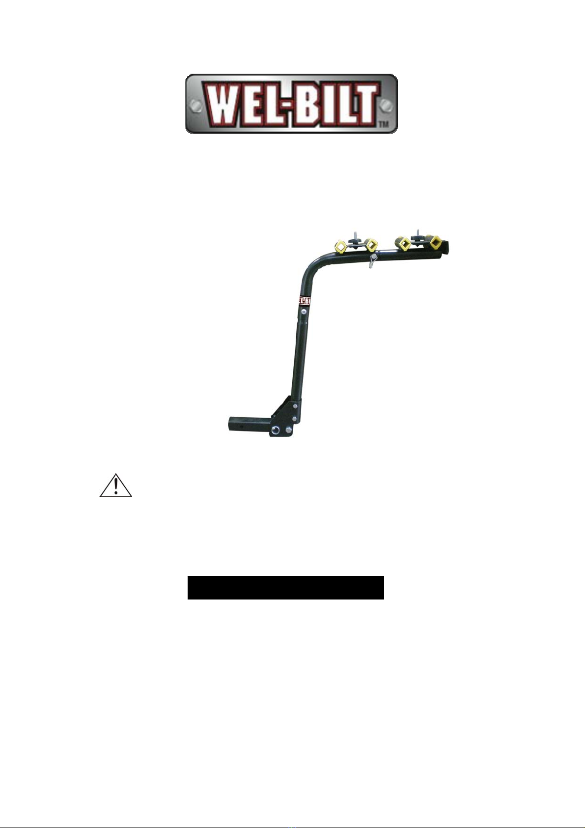
4-BIKE HITCH RACK
OWNER’S MANUAL
WARNING: Read carefully and understand all
INSTRUCTIONS before operating. Failure to follow the
safety rules and other basic safety precautions may result
in serious personal injury.
Item # 193024
Page of 112
Thank you very much for choosing a Wel-Bilt™ product! For future reference, please complete
the owner’s record below:
Model: _______________ Purchase Date: _______________
Save the receipt, warranty and these instructions. It is important that you read the entire manual
to become familiar with this product before you begin using it.
This product is designed for certain applications only. The distributor cannot be responsible for
issues arising from modification. We strongly recommend this product not be modified and/or
used for any application other than that for which it was designed. If you have any questions
relative to a particular application, DO NOT use the product until you have first contacted the
distributor to determine if it can or should be performed on the product.
For technical questions please call 1-800-222-5381.
INTENDED USE
This 4-bike hitch rack mounts to any 2in. receiver hitch for hauling up to 4 bicycles. It is not
recommended for use with trailers or 5th wheel.
TECHNICAL SPECIFICATIONS & PACKING LIST
Item Description
Load Capacity 120 Lbs. (54.5kgs)
Hitch Size 2in.(5cm) standard
GENERAL SAFETY RULES
WARNING: Read and understand all instructions. Failure to follow all instructions listed
below may result in serious injury.
CAUTION: Do not allow persons to use or assemble this bike hitch rack until they
have read this manual and have developed a thorough understanding of how the bike hitch
rack works.
WARNING: The warnings, cautions, and instructions discussed in this instruction
manual cannot cover all possible conditions or situations that could occur. It must be
understood by the operator that common sense and caution are factors which cannot be built into
this product, but must be supplied by the operator.
SAVE THESE INSTRUCTIONS

Page of 113
WORK AREA
When assembling, installing, or removing the bike hitch rack
•Keep work area clean, free of clutter and well lit. Cluttered and dark work areas can cause
accidents.
•Keep children and bystanders away while assembling, installing or removing the bike hitch
rack. Distractions can cause loss of control, so visitors should remain at a safe distance from the
work area.
•Be aware of all power lines, electrical circuits, water pipes and other mechanical hazards
near your work area, particularly those hazards below the work surface hidden from the
operator’s view that may be unintentionally contacted and may cause personal harm or property
damage.
PERSONAL SAFETY
•Stay alert, watch what you are doing and use common sense when using the bike hitch rack
•Secure all bicycles loaded on the bike hitch rack.
•Never use with a trailer jack or 5th wheel.
BIKE HITCH RACK USE AND CARE
•Do not modify the bike hitch rack in any way . Unauthorized modification may impair the
function and/or safety and could affect the life of the equipment. There are specific applications
for which the bike hitch rack was designed.
•Always check for damaged or worn parts before using the bike hitch rack. Broken parts
will affect the bike hitch rack operation. Replace or repair damaged or worn parts immediately.
•Do not exceed the bike hitch rack 120-lb. load capacity.
ASSEMBLY
Recommended Tools:
1 ea.-17mm combination wrench
1 ea.-19mm combination wrench
1 ea.-24mm combination wrench
TIP: Refer to parts diagram during assembly to see fully assembled product.
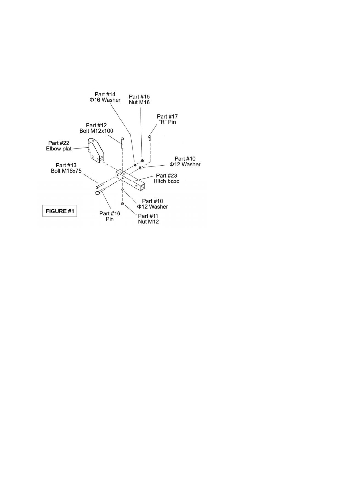
Step 1: Assemble turn plate and base
Hardware Needed:
Qty 1: Elbow Plate (Part #22)
Qty 1: Hitch Base (Part #23)
Qty 2: Ф12 washer (Part #10)
Qty 1: Nut M12 (Part #11)
Qty 1: Bolt M12X100 (Part #12)
Qty 1: Bolt M16X75 (Part #13)
Qty 1: Ф16 washer (Part #14)
Qty 1: Nut M16 (Part #15)
Page of 114
Qty 1: Pin (Part #16)
Qty 1: “R” Pin (Part #17)
See figure#1 below. Attach turn elbow plate (Part #22) onto hitch base (Part #23) using M16X75 bolt,
M16 nut and washer (see specific hole location below). Next, insert Pin (Part #16) to the second
hole (see below) using “R” pin and washer to secure it.
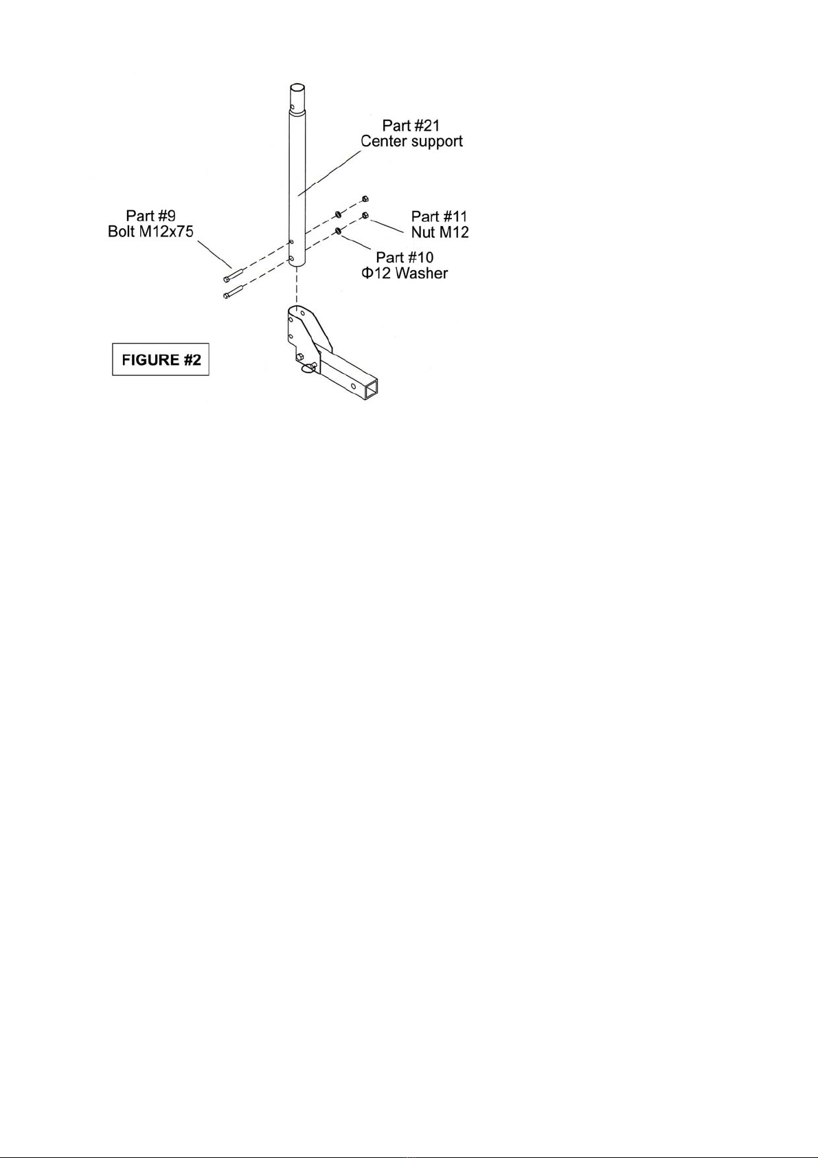
Step 2: Attach bottom support to turn plate from step 1.
Hardware Needed:
Qty 1: Center support (Part #21)
Qty 2: Bolt M12X75 (Part #9)
Qty 2: Ф12 washer (Part #10)
Qty 2: Nut M12 (Part #11)
See figure #2 below. Attach under support into the turn plate using M12X75 bolt, M12 nut and
washer.
Page of 115
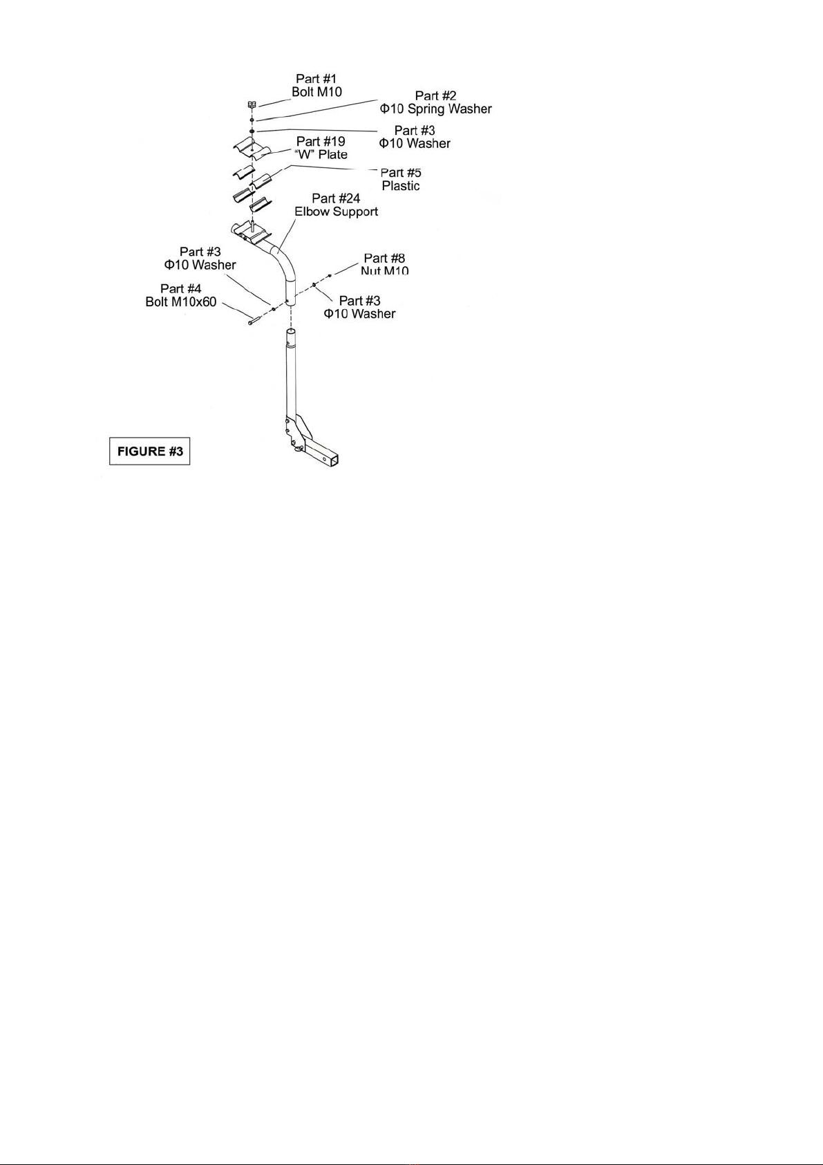
Step 3: Attach Top Support Plate
Hardware Needed:
Qty 1: Elbow Support Part #24)
Qty 1: Bolt M10 (Part #1)
Qty 1: Ф10 spring washer (Part #2)
Qty 3: Ф10 washer (Part #3)
Qty 1: Bolt M10X60 (Part #4)
Qty 4: Plastic (Part #5)
Qty 1: Nut M10 (Part #8)
Qty 1: “W” Plate (Part #19)
Note that the “W” Plate (Part #19)and plastic (Part #5) are pre-assembled. Next place “W” plate
onto the elbow support (Part #24). Attach the elbow support (Part #24) onto bottom (under) center
support (Part #21) using M10X60 bolt (Part #4), M10 nut (Part #8) and two washers (Part #3). See
below.
Page of 116
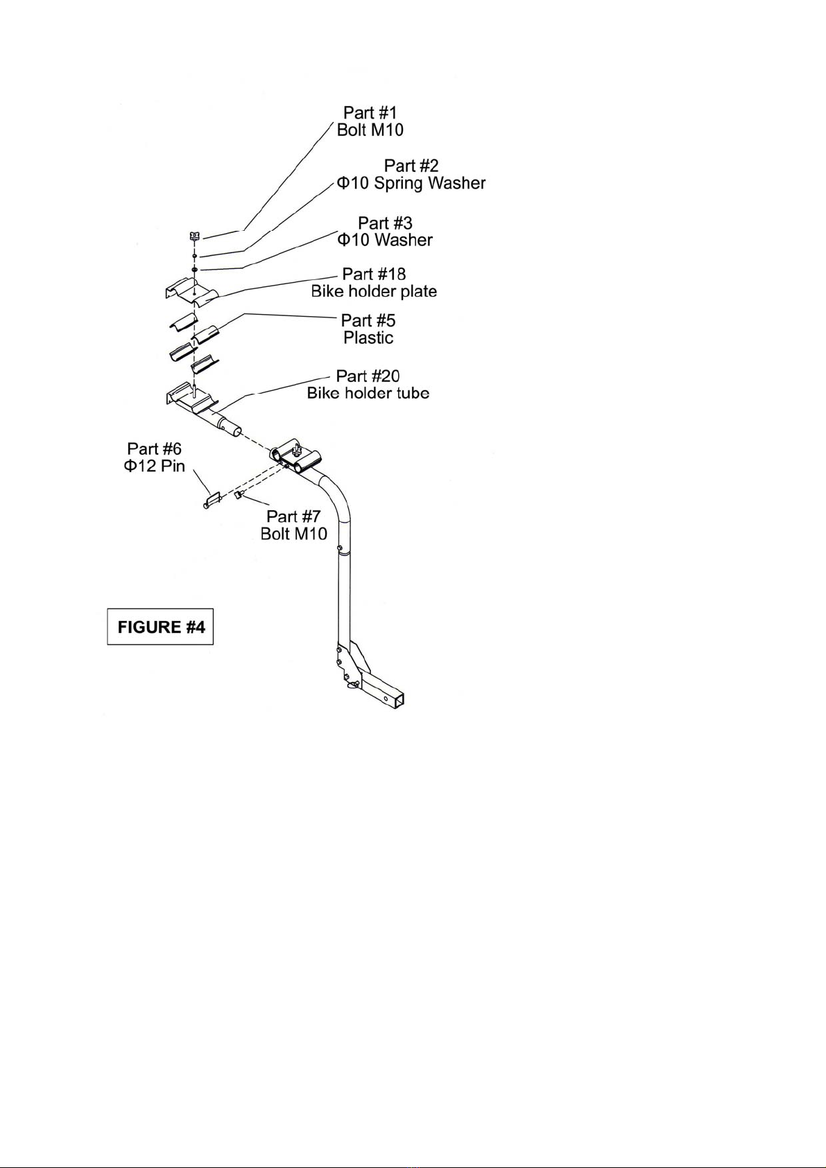
Step 4 Connect assembled Join tube
Hardware Needed:
Qty 1:Bike holder Tube (Part #20)
Qty 1:Bolt M10 (Part #1)
Qty 1: Ф10 spring washer (Part #2)
Qty 1: Ф10 washer (Part #3)
Qty 4: Plastic (Part #5)
Qty 1: Ф12 pin (Part #6)
Qty 1: Bolt M10 (Part #7)
Qty 1: Bike Holder Plate (Part #18)
Note the bike holder plate (Part #18)and plastic (Part #5) are pre-assembled onto the bike holder
tube (Part #20). Connect the bike holder tube (Part #20) onto the elbow support (Part #24) withФ12
pin (Part #6).
Page of 117
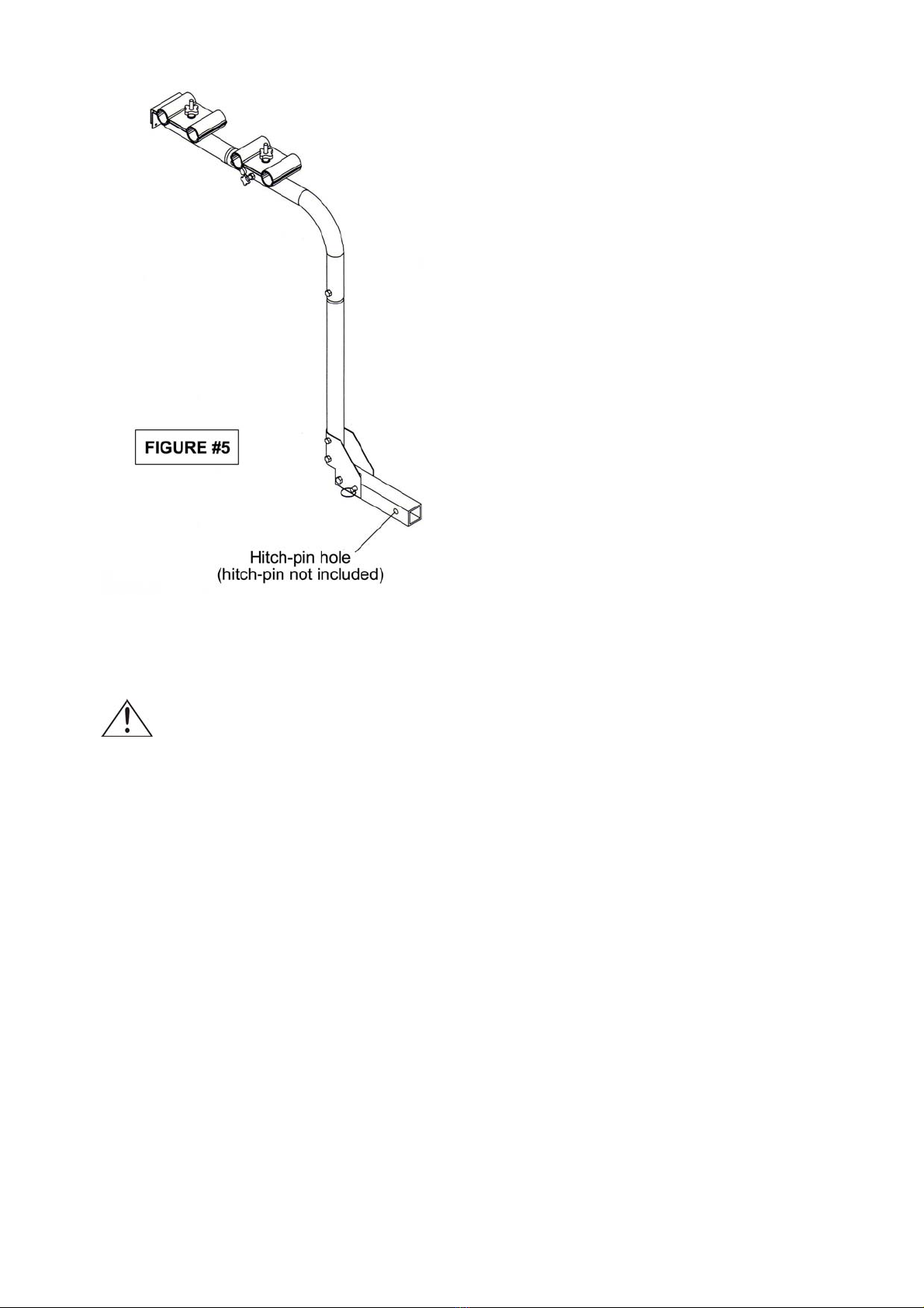
Step 5. Assembly Completed
IMPORTANT! Check that all connections are tight.
Attach bike hitch rack to vehicle receiver hitch, securing it with a hitch pin (not included).
Page of 118
OPERATION
WARNING: RISK OF FIRE/FIRE HAZARD
•Never allow loads or items on the bike hitch rack to block or impede exhaust from vehicle.
•This can cause a fire or damage to personal property or vehicle.
Step 1: Two person installation is recommended to lift the bike hitch rack into place.
Step 2: Lift the bike hitch rack and insert receiver mounting bar into the hitch receiver on the
vehicle.
Step 3: Line up the horizontal hole in the receiver mounting bar with the hole in your hitch.
When the holes line up, place your hitch pin (or locking mechanism) through the holes
to secure the bike hitch rack.

Page of 119
MAINTENANCE
•Maintain your bike hitch rack. It is recommended that the general condition of the rack be
examined before it is used. Keep the rack in good repair by adopting a program of conscientious
repair and maintenance in accordance with the recommended procedures found in this manual.
•Keep the rack clean. A properly maintained bike hitch rack will work more effectively. Keep all
of the parts dry, clean, and free from oil and grease.
•Cleaning. Use only soap and a damp cloth to clean your bike hitch rack.
Page of 1110
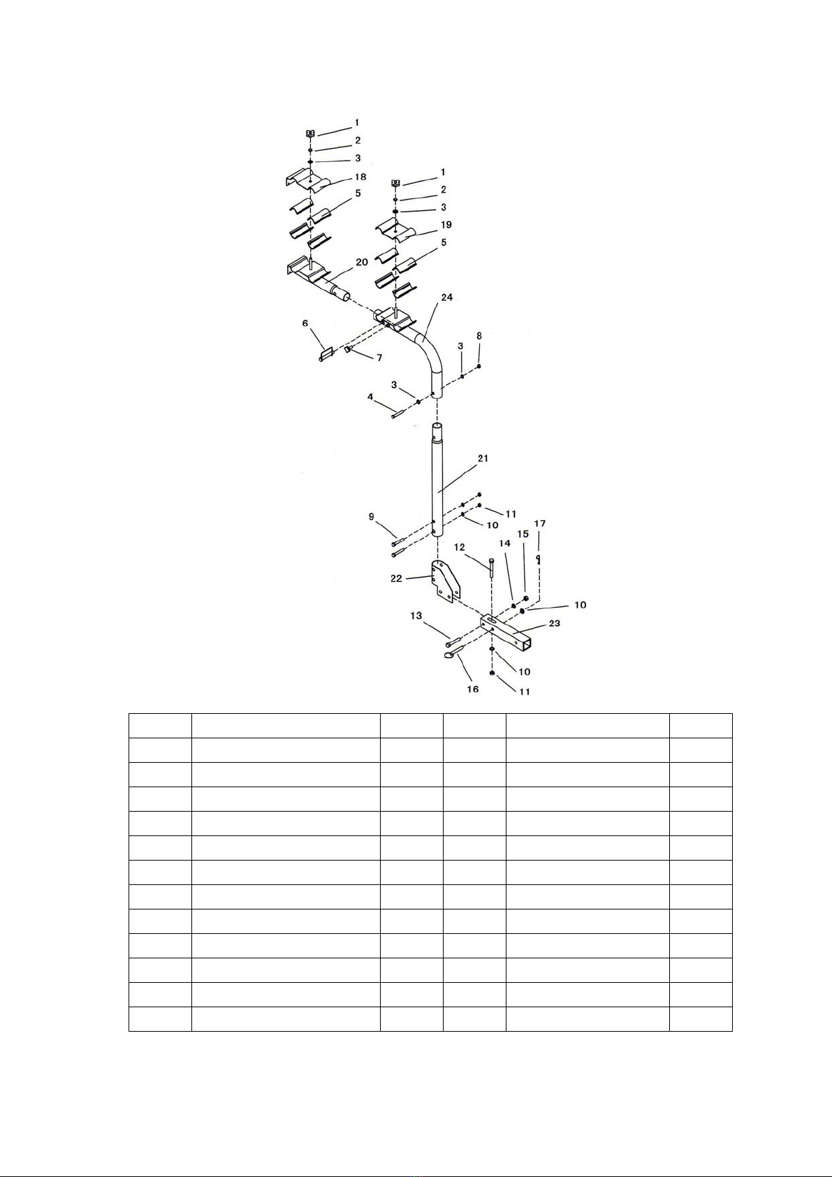
DIAGRAM & PARTS LIST
Part# Description Qty. Part# Description Qty.
1 Bolt M10 2 13 Bolt M16X75 1
2 Ф10 Spring Washer 2 14 Ф16 Washer 1
3 Ф10 Washer 4 15 Nut M16 1
4 Bolt M10X60 1 16 Pin 1
5 Plastic 8 17 “R” Pin
1
6 Ф12 Pin 1 18 Bike Holder Plate 1
7 Bolt M10 1 19 “W” Plate
1
8 Nut M10 1 20 Bike Holder Tube 1
9 Bolt M12X75 2 21 Center Support 1
10 Ф12 Washer 3 22 Elbow Plate 1
11 Nut M12 3 23 Hitch Base 1
12 Bolt M12X100 1 24 Elbow Support 1
For replacement parts and technical questions, please call 1-800-222-5381.
Indice


