Westermo ED-10 TCP Manuale utente

Industrial Ethernet adapter
INSTALLATION MANUAL
6609-2202
. estermo.se
ED-10
©Westermo Teleindustri AB • 2001 • REV. A
Galvanic
Isolation Transient
Protection Balanced
Transmission CE
Approved


36609-2202
Contents
1. Introduction .......................................................................................................................................................................... 4–5
2. Safety ............................................................................................................................................................................................................ 5
3. Specification ......................................................................................................................................................................... 6–7
4. Installation ....................................................................................................................................................................................... 8
4.1 Connections ............................................................................................................................................ 8–10
4.2 DIP s itch settings .............................................................................................................................. 11
4.3 LED indicators ............................................................................................................................................ 12
4.4 Installation of ED-Tool .................................................................................................................. 13
5. Functional description ......................................................................................................................... 14–15
6. Configuration ........................................................................................................................................................................ 16
6.1 Configuration by ED-Tool ............................................................................................. 16–22
6.2 Configuration by terminal ............................................................................................ 22–24
6.3 Delayed configuration ......................................................................................................... 25–26
6.4 Configurable parameters ............................................................................................... 27–31
7. Application examples ............................................................................................................................ 32–34

46609-2202
1. Introduction
The ED-10 is an Industrial Ethernet Adapter with a serial interfa e. The type of serial
interfa e is sele table between RS-232 and RS-422/485. The Ethernet interfa e is
10BaseT and TCP/IP Internet Proto ols are used for network ommuni ation.
Two ED-10 units an be used to provide a serial point to point link over a TCP/IP net-
work. Ea h ED-10 passes data from its serial interfa e to the other unit's serial interfa e.
This enables long distan e serial onne tions over pre-existing networks.
It is also possible to ommuni ate one to many (e.g. master/slaves), by using a broad-
ast address.
If the ustomer writes it’s own PC appli ation software, the network interfa e of ED-10
an be dire tly a esed.
A software example an be downloaded from the Westermo web site
(www.westermo.se). This example demonstrates how a PC sends network data dire tly
to the ED-10. Sour e ode, in C, is in luded.
ED-10 point to point onne tion
ED-10 one to many onne tion
ED-10 dire tly a essed by a PC-appli ation
543
2
1
543
2
1
Serial
Device Serial
Device
ED-10
Network
ED-10
543
2
1
543
2
1
Serial
Master
Collision Domain
Serial
Slave
Serial
Slave
ED-10 ED-10
Network
Network
543
2
1
ED-10
543
2
1
ED-10
Serial
Slave
543
2
1
ED-10 Serial device

56609-2202
The ED-10 is ideal for use in the industrial environment. It is housed in the Westermo
DIN rail box and has a wide range power input, isolated interfa es and transient prote -
tion.
The ED-10 is approved for Industrial EMC Immunity (EN50082-2) and EMC Emission
(EN50081-1). All relevant requirements of the Low Voltage Dire tive are fulfilled.
The ED-10 uses the TCP/IP Internet Proto ol Suit (TCP/IP) to transfer data over the
network.
TCP/IP is a set of proto ols that enables ommuni ation a ross lo al and wide area
networks and in ludes proto ols su h as TCP, UDP, IP , ARP, RARP, ICMP. Although
not all these proto ols are needed for a network data transfer.
The ED-10 uses TCP for remote onfiguration ( onfiguration mode) and UDP for
transmitting the serial data over network, i.e. UDP is used in appli ation mode.
UDP uses pa ket delivery of data, meanwhile TCP uses stream transport.
The ED-10 an be onfigured both remotely over the TCP/IP network and lo ally via the
RS-232 interfa e, making the unit very flexible.
Lo al or remote onfiguration is a hieved either by using the ED-Tool Windows‚ soft-
ware or by using a terminal programme (e.g. HyperTerminal for lo al onfiguration or
Telnet for remote onfiguration).
A DIP swit h setting also allows the unit to be reset to fa tory default, if required.
2. Safety
Serial interfa e CH1 is not isolated from CH2. They must only be onne ted to SELV
ir uits.
The Network interfa e must only be onne ted to TNV or SELV ir uits.
See EN 60950:1996 for definitions.
Sound installation pra ti e, as defined by appli able lo al odes or regulations, shall be
followed in every instan e in whi h su h pra ti e is appli able.

66609-2202
3. Specification
Net ork Interface 10BASE-T. IEEE std 802.3, 2000 Edition.
Data rate 10 Mbit/se , half duplex.
Me hani al RJ-45 Modular Ja k (ISO/IEC 8877:1992),
Unshielded or shielded (UTP/STP).
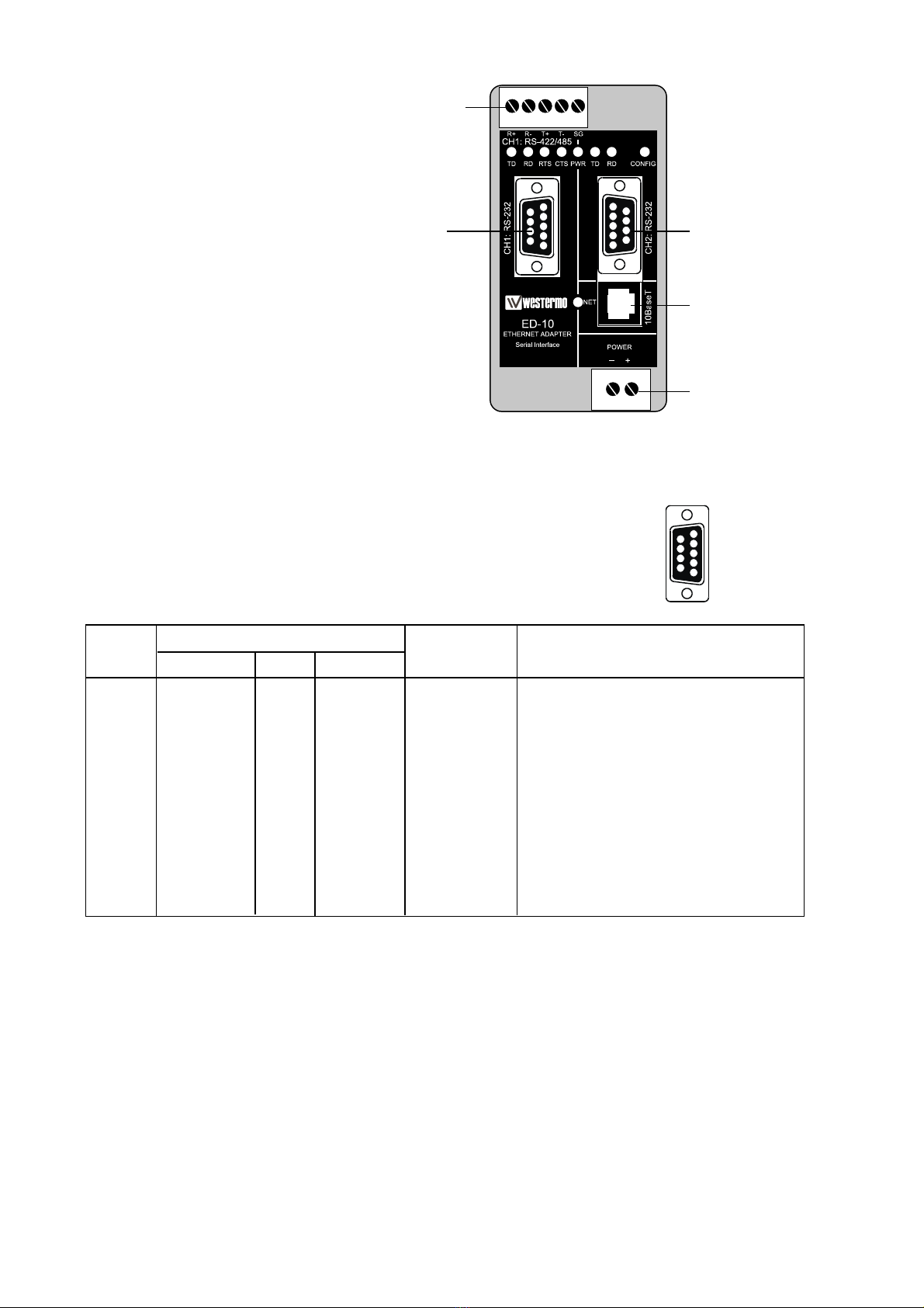
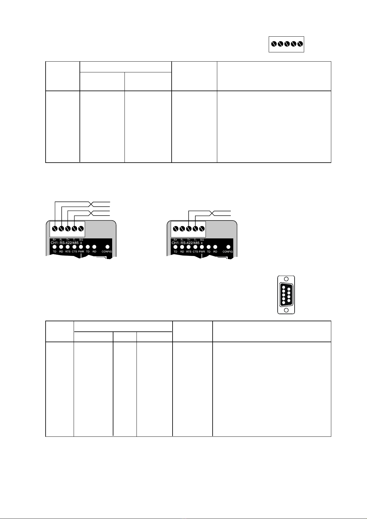
Serial Interface 1 (CH 1) RS-232 or RS-422/485
Data rate 300–115 200 bit/s Full, half duplex or simplex.
Data format 7–8 Data Bits, Odd, Even or None Parity Bit,
1–2 Stop Bits (2 stop bits when no parity only)
Control signals* RTS, CTS, DSR
Termination** Termination and fail safe, on or off
Me hani al RS-232: 9-pin female D-sub.
RS-422/485: S rew Terminal.
Serial Interface 2 (CH 2) RS-232 (used for lo al onfiguration only)
Data rate 19 200 Bit/se
Data format 8 Data Bits, No Parity Bit, 1 Stop Bit
Me hani al 9-pin female D-sub.
Po er Interface
Rated voltage 12–49 V AC / 10–74 V DC polarity independent.
Rated urrent 350 mA
Rated frequen y 50–60 Hz
Me hani al S rew Terminal.
Isolation Fun tional and safety
Power Interfa e to 4.2 kV DC, 3 kV RMS @ 50–60 Hz. EN 60950:1996
all other Interfa es***
Network Interfa e 2.1 kV DC, 1.5 kV RMS @ 50–60 Hz. Applied for 60 se
to serial interfa e as spe ified in 5.3.2 of EN 60950:1996.
Transient Protection
Power Interfa e ±4 kV, EN 61 000-4-5:1995 Class 4
Network Interfa e ±2 kV, EN 61 000-4-5:1995 Class 3
Serial Interfa e** ±2 kV, EN 61 000-4-5:1995 Class 3
Serial Interfa e* ±0.5 kV, EN 61 000-4-5:1995 Class 1
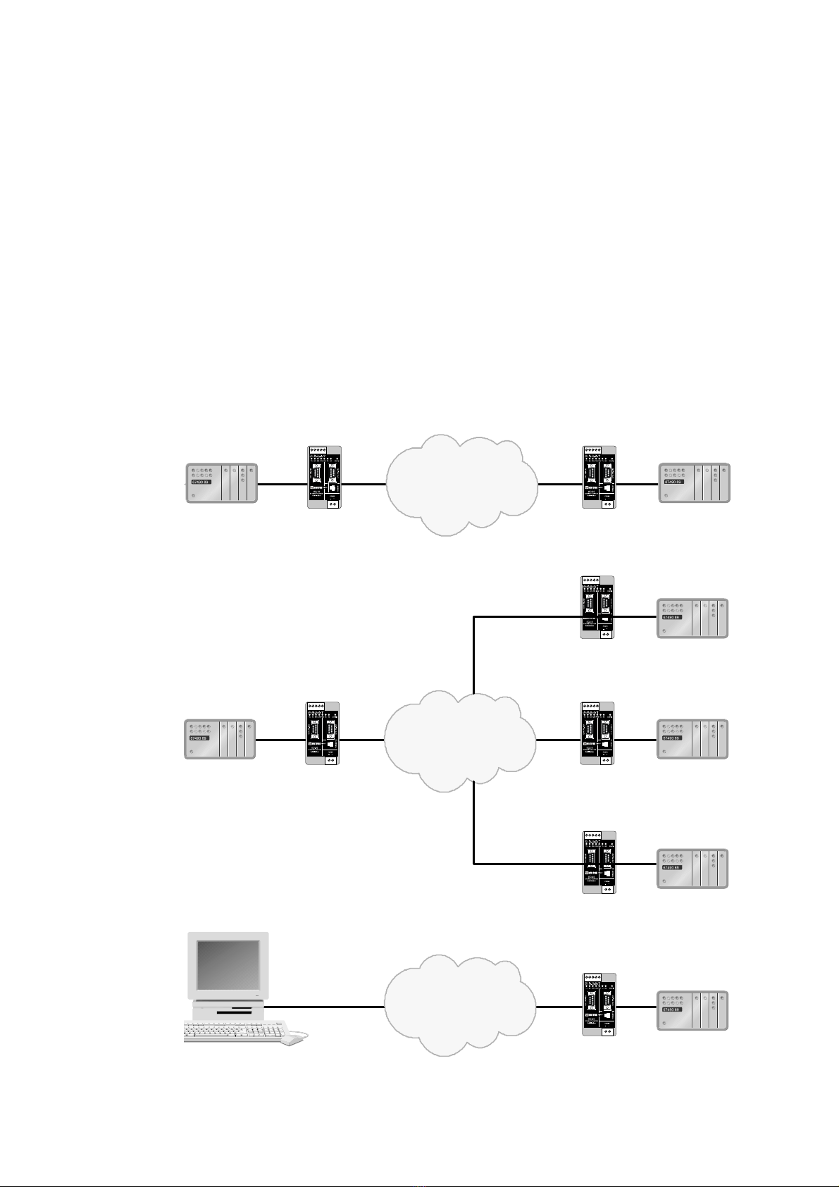
Application Serial/Network onversion
Laten y (minimum) Serial to Network: 2 ms
Network to Serial: 8 ms
Throughput (maximum) 57.6 kbit/s (1.44 Mbyte data)
Network proto ols UDP, IP, ARP
* RS-232 only.
** RS-422/485 only.
*** Power to network interfa e, 1.5 kV RMS @ 50–60 Hz fun tional isolation.

76609-2202
Configuration Remotely over Network or lo ally at serial interfa e.
Windows based PC-programme or simple terminal
programme. Delayed onfigure possible.
Indicators (LED) TD, RD, CTS, RTS, PWR, TD, RD, CONFIG, NET
Environment 5–50°C
5–95% REL non ondensing
Dimension 55x100x128 mm (WxHxD)
Weight 0.35 kg
Mounting On 35 mm DIN-rail
Approvals CE

86609-2202
4. Installation
Power onne tion is made at
lower right s rew terminal.
Conne t PLC, omputer et
to serial interfa e CH1. Use
RS-232 or RS-422/485.
Serial interfa e CH2: RS-232
shall be used for onfiguration
only.
4.1. Connections
CH1 is used for the serial/network onversion.
Type of interfa e (RS-232 or RS422/485) onne ted
must also be set at DIP swit h S1.
CH1: RS-232 Connections (D-sub connector), DCE
54321
1
2
3
4
5
6
7
8
9
Pin Signal Name*
Number Des ription V.24 RS-232C Dire tion** Des ription
1 DCD*** 109 CF Out Data Carrier Dete t
2 RD 104 BB Out Re eived Data
3 TD 103 BA In Transmitted Data
4 DTR 108.2 CD In Data Terminal Ready
5 SG 102 AB In/out Signal Ground
6 DSR 107 CC Out Data Set Ready, ED-10 ready
7 RTS 105 CA In Request to Send
8 CTS*** 106 CB Out Clear to Send
9 RI 125 CE – Ring Indi ator, not onne ted
* Fun tionality might differ from standard, see hapter 6.4
** Dire tion relative ED3-10.
*** Follows DSR (CTS will be dea tivated as required by flow ontrol)
RS-232 able must not ex eed 15 m
CH1: RS-422/485
S rew terminal
CH1: RS-232
9-pin D-sub
CH2: RS-232
9-pin D-sub
onfiguration only
Network
RJ-45 onne tion
Power
s rew terminal

96609-2202
CH1: RS-422/485 Connections (Upper left scre terminal)
54321
Terminal Signal Name*
Number Marked A ording
on ED-10 to Standard Dire tion** Des ription
1 SG – – Not onne ted
2 T– B Out/In RS422/485 4-wire Transmitter /
RS485 2-wire T– and R–
3 T+ A Out/In RS422/485 4-wire Transmitter /
RS485 2-wire T+ and R+
4 R– B’ In RS422/485 4-wire Re eiver
5 R+ A’ In RS422/485 4-wire Re eiver
* Numbered right to left (front view).
** Dire tion relative ED-10.
Twisted pair able is re ommended
CH2: RS-232 Connections (D-sub connector), DCE
5
4
3
2
1
9
8
7
6
Pin Signal Name*
Number Des ription V.24 RS-232C Dire tion** Des ription
1 DCD 109 CF – Data Carrier Dete t, not onne ted
2 RD 104 BB Out Re eived Data
3 TD 103 BA In Transmitted Data
4 DTR 108.2 CD – Data Terminal Ready, not onne ted
5 SG 102 AB In/out Signal Ground
6 DSR 107 CC – Data Set Ready, not onne ted
7 RTS 105 CA In Request to Send, not used
8 CTS 106 CB Out Clear to Send, not used
9 RI 125 CE – Ring Indi ator, not onne ted
* Fun tionality might differ from standard, see hapter 6.4
** Dire tion relative ED-10.
RS-232 able must not ex eed 15 m
54321
4-wire
54321
2-wire

10 6609-2202
Ethernet 10Base-T Connection (RJ-45 connector),
straight function (no crossover)
Conta t Signal Name Dire tion1 Des ription
1 TD+ Out Transmitted Data
2 TD- Out Transmitted Data
3 RD+ In Re eived Data
4 Not onne ted
5 Not onne ted
6 RD- In Re eived Data
7 Not onne ted
8 Not onne ted
* Dire tion relative ED-10.
CAT 5 able is re ommended.
Unshielded (UTP) or shielded (STP) onne tor might be used.
1
2
34
5678
Altri manuali per ED-10 TCP
1
Indice
Altri manuali Westermo Adattatore

Westermo
Westermo EDW-100 Manuale utente

Westermo
Westermo EDW-120 Manuale utente

Westermo
Westermo ED-10 TCP Manuale utente

Westermo
Westermo AD-01 Manuale utente

Westermo
Westermo FD-10 Manuale utente

Westermo
Westermo EDW-100 EX Manuale utente

Westermo
Westermo IDW-90 Manuale utente

Westermo
Westermo EDW-120 Manuale utente

Westermo
Westermo ID-90 Manuale utente


