
Wiener MPOD LV Manuale utente
25. July 2012 1 Version 2.5.5
MPOD HV& LV
Power Supply System
Technical Manual

General Remarks
The only purpose of this manual is a description of the product. It must not be interpreted as
a declaration of conformity for this product including the product and software.
W IeNeR revises this product and manual without notice. ifferences of the description in
manual and product are possible.
W IeNeR excludes completely any liability for loss of profits, loss of business, loss of use
or data, interrupt of business, or for indirect, special incidental, or consequential damages of
any kind, even if W IeNeR has been advises of the possibility of such damages arising
from any defect or error in this manual or product.
Any use of the product which may influence health of human beings requires the express
written permission of W IeNeR.
Products mentioned in this manual are mentioned for identification purposes only. Product
names appearing in this manual may or may not be registered trademarks or copyrights of
their respective companies.
No part of this product, including the product and the software may be reproduced,
transmitted, transcribed, stored in a retrieval system, or translated into any language in any
form by any means with the express written permission of W IeNeR.
Control Cabinet
In the context of this user manual, the control cabinet must fulfill the requirements on fire-
protective enclosures according to EN 60950 / IEC 60950 / UL 60950.
All devices are intended for operation in control cabinets or in closed areas. The LAN
connection and all wire connections between the different system parts must be done via
shielded cable with conductive connector shells, which are fixed with screws.
Furthermore, an additional fire-protective enclosure is required which must not affect proper
air circulation.
25. July 2012 i
Mains Voltage and Connection
The Power supplies are equipped with a “World”- mains input (rated voltage range: 100-240
VAC, frequency: 50-60 Hz, rated current: 16 A). Before connecting to the mains please
double-check correspondence.
Mains input connection at the power supply side is done with a 3-pin HIRSCHMANN
connector or power terminals. There is no main fuse inside. A circuit breaker for overcurrent
protection 16A, type B or C (EN / IEC 60898, V E 0641), has to be installed externally.
Before disconnection the HIRSCHMANN connector, the power supply should be switched
into standby state. (Use the ON/OFF-Switch of the front pannel of the MPO system)
Hirschmann. Signal escription Color of the Wire
Pin 1 L Phase black or brown
Pin 2 N Return, Neutral blue
Pin 3 not connected
Earth PE Protective Earth green/yellow
Connection to Earth
Safety
After connecting the Power box to the mains, the mains input module is powered
permanently. Filter and storage capacitors of the power factor correction module are charged
with about 400VDC. Any C-On-Signal as well as a power switch at control board (if any
installed) operates as a low voltage C on/off switch only and not as a mains breaker.
Therefore it becomes dangerous if the box cover is open. In this case a lot of
components on high voltage potential get touchable!
Before starting any kind of work inside the power box remove the unit from
mains and wait a couple of minutes with your activities! Discharge the primary
DC Filter capacitors by use of a well isolated 22 ohm 10W resistor.
We recommend in case of any malfunction to send the power box to Wiener or
to one of our representative for service
The backplane is connected to 385 V DC voltage. So never touch the backplane
or its connectors!
The HV Modules produce very high voltage which may be mortal danger if
handled improperly. Please read the separate manuals of the HV modules for
detailed information!
25. July 2012 ii

Declaration of Conformity
Low Voltage irective 73/23/EEC and EMC irective Art. 10.1 of 89/336/EEC
WIe Ne R
Plein & Baus GmbH
declare under our own responsibility that the product
MPOD Power Supply System
Items: 0MPV.xxxx, 0BP0.9003, 0316.0070, 0R00.0002
is in accordance with the following standards or standardized documents:
1. EN 60 950 1:2001
+ Corr:2004-09 Niederspannungsrichtlinie [low voltage
directive]
2. EN 61 000 6 3:2001 Störaussendung EMA [RF emission]
EN 55 022:1998
+ Corr:2001 + A1:2000 Kl. B
Störspannung [conducted noise]
EN 55 022:1998
+ Corr:2001 + A1:2000 Kl. B
Störfeldstärke [radiated noise]
EN 61 000-3-2:2001 Oberschwingungen [harmonics]
EN 61 000-3-3:1995 +Corr:1997 +A1:2001 Spannungsschwankungen [flicker]
3. EN 61 000 6 2:2001 Störfestigkeit EMB [immunity]
EN 61 000-4-6:1996 + A1:2001 HF-Einströmung [injected HF currents]
EN 61 000-4-3:1996 + A1:1998 + A2:2001 HF-Felder [radiated HF fields] incl.
”900MHz”
EN 61 000-4-4:1995 + A1:2001 Burst
EN 61 000-4-5:1995 + A1:2001 Surge
EN 61 000-4-11:1994 + A1:2000 Spannungs-Variationen [voltage
variations]
EN 61 000-4-2:1995 + A1:1998 + A2:2001 ES
Conditions:
This unit is not a final product and is foreseen for use inside a closed cabinet. The supplying
of loads over long distances (>3m) needs possibly additional RF rejection hardware to get in
conformity of the definition.
Name and signature of authorized person Place and ate
Manfred Plein
Techn. irector
April 2008
25. July 2012 iii

Contents
eclaration of Conformity................................................................................................iii
1 General Information................................................................................................1
1.1 Mpod Features .............................................................................................................1
1.2 Mpod Crate - standard types..........................................................................................2
1.3 Mpod Mini crate............................................................................................................3
2 LV Modules..............................................................................................................4
2.1 MPO Low Voltage Module Versions.........................................................................5
2.2 Combined Power & Sense Connector Pin Assignment (standard female type).............5
2.3 Sense & Control Connector Pin Assignment (modules with mixed SUB37 +
SUB37-8).........................................................................................................................7
2.4 Power Connector Pin Assignment (modules with mixed SUB37 + SUB37-8)........7
3 HV Modules .............................................................................................................9
4 Mpod Controller....................................................................................................12
5 Local Control .........................................................................................................14
5.1 Introduction.................................................................................................................14
5.2 Usage of the rotary controls.........................................................................................14
5.3 Main Menu Overview..................................................................................................16
5.4 Channel Menu Overview.............................................................................................17
6 Remote Control / Software....................................................................................18
6.1 Software Setup for Microsoft Windows......................................................................18
6.2 Web Browser...............................................................................................................20
6.3 NetSNMP....................................................................................................................21
6.4 ISEG High voltage module special commands............................................................26
6.5 Change of community names / setting of passwords...................................................31
6.6 MIB Browser...............................................................................................................32
6.7 A BASH Simple Script for SNMP..............................................................................32
6.8 Mpod SNMP Parameter List (most common).............................................................34
6.9 LabView Control Program (NETSNMP)....................................................................35
6.10 C++ programming (NetSNMP).................................................................................35
7 Mpod Crate............................................................................................................37
8 Primary Power Supply..........................................................................................37
8.1 Power Box ata Sheet.................................................................................................37
9 Mpod Low Voltage module MPV 8xx data sheet................................................38
10 SNMP examples for MPOD and high voltage EHS/EDS module...................40
11 WIENER SNMP Parameter structure...............................................................43
12 MPOD Firmware Update....................................................................................52
25. July 2012 iv

Figures
Tables
25. July 2012 v
1 General Information
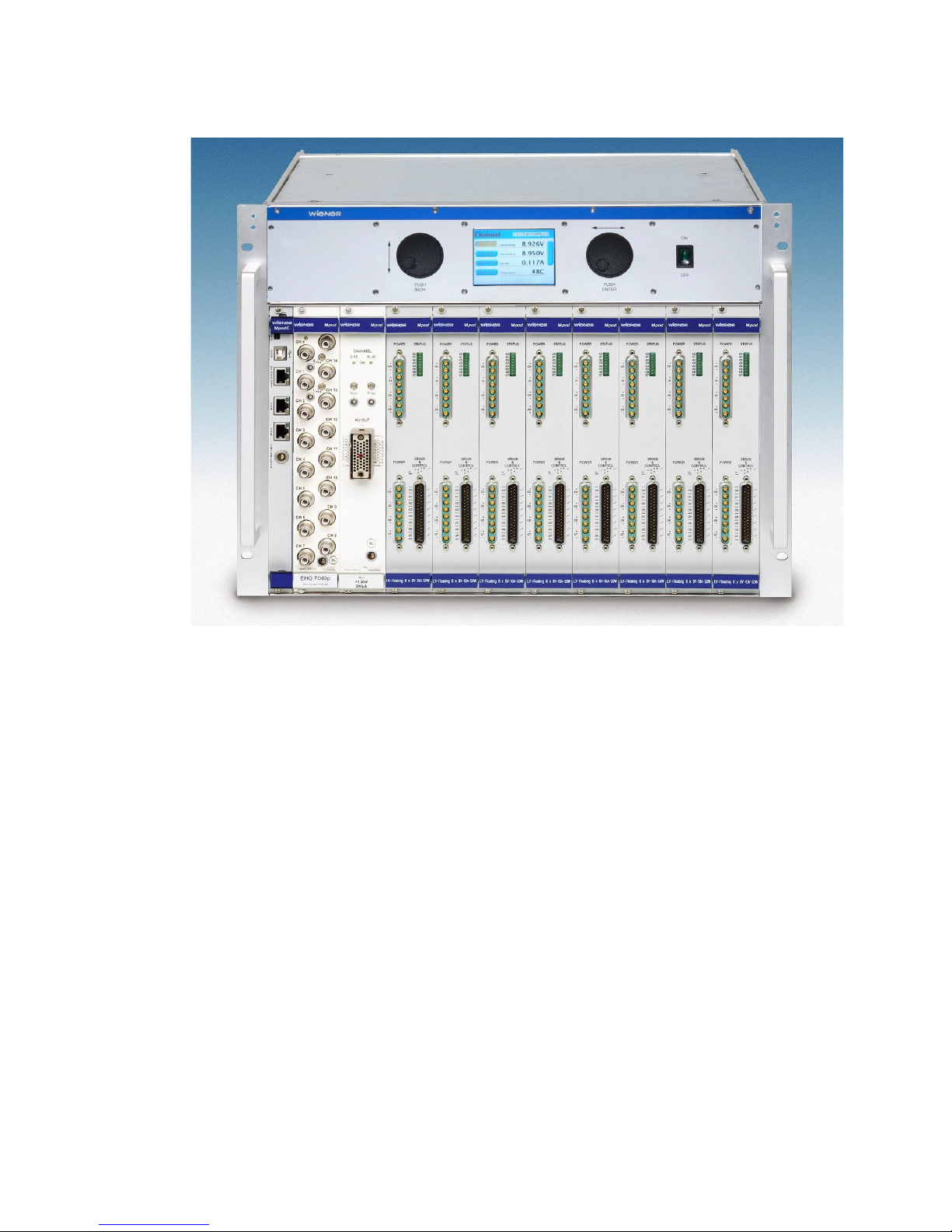
Mpod LX crate with mixed low and high voltage modules
1.1 M
pod
Features
Mpod is a mainframe for multi-channel high voltage (HV) and low voltage (LV) power supply
modules. A unique flexibility is given by outfitting the MPO crate with either the LV or HV
backplane only or with both to allow combined use of LV and HV modules. The full size Mpod
crate has 10 slots for power modules which provides a high number of output channels. Its
modular design makes the customer able to easily replace the fan tray, the controller, the
primary power supply or the optional air filter.
●10 module slots for up to 80 LV channels / up to 320 HV channels
●8U high for bottom cooling air intake, optional 9U high as desktop or front / side intake
with 1U dust filter
●Modules and controller outputs can be placed either at front or rear side (picture above
shows front side)
●LV: 8 channels (0- 8/16/30/60V/120V, 50W / channel, floating
●HV: 320/160/80 or 40 channels (0- 2,5/4/6kV/8kV/10kV), channel- or module wise
floating or common ground
●Low noise and ripple
●Individually controlled output channels (voltage and current), programmable warning
and trip levels
●MPO Controller with Ethernet (TCP/IP) / CANbus / USB Combi-interface, Interlock
●Ethernet port with integrated Web server, programmable with SNMP protocol via
TCP/IP, OPC Server
25. July 2012 1 Version 2.5.5
●CE conform EN 50 081/82 part 1 (EN 50 022 B)
●safety in accordance with EN 60 950
●Sinusoidal mains current EN 61000-3-2
1.2 Mpod Crate standard types
The following crate types are standardized configurations with 8U high chassis. Optionally a
filter frame is available with bottom or front air inlet which increases the height to 9U.
Other configurations and mixed system with part of the crate outfitted with PCI or VME
backplanes are available on request.
Type Slots Remote control
interface
Local control /
display
Backplane HV
power
Output
Position
Mpod EC 10 Ethernet, CAN, USB - HV/LV 600W front
Mpod EC R 10 Ethernet, CAN, USB - HV/LV 600W rear
Mpod LX 10 Ethernet, CAN, USB Yes, LC HV/LV 600W front
Mpod LX R 10 Ethernet, CAN, USB Yes, LC HV/LV 600W rear
Mpod EC LV 10 Ethernet, CAN, USB - LV - front
Mpod EC LV R 10 Ethernet, CAN, USB - LV - rear
Mpod EC HV 10 Ethernet, CAN, USB - HV 600W front
Mpod EC HV R 10 Ethernet, CAN, USB - HV 600W rear
Mpod 2H 10 Ethernet, CAN, USB - HV 1200W front
Mpod 2H R 10 Ethernet, CAN, USB - HV 1200W rear
Mpod 2H LX 10 Ethernet, CAN, USB Yes, LC HV 1200W front
Mpod 2H LX R 10 Ethernet, CAN, USB Yes, LC HV 1200W rear
(CAN-bus for HV modules only, disabling Ethernet communication may be necessary for
ISEG CAN-HV control software)
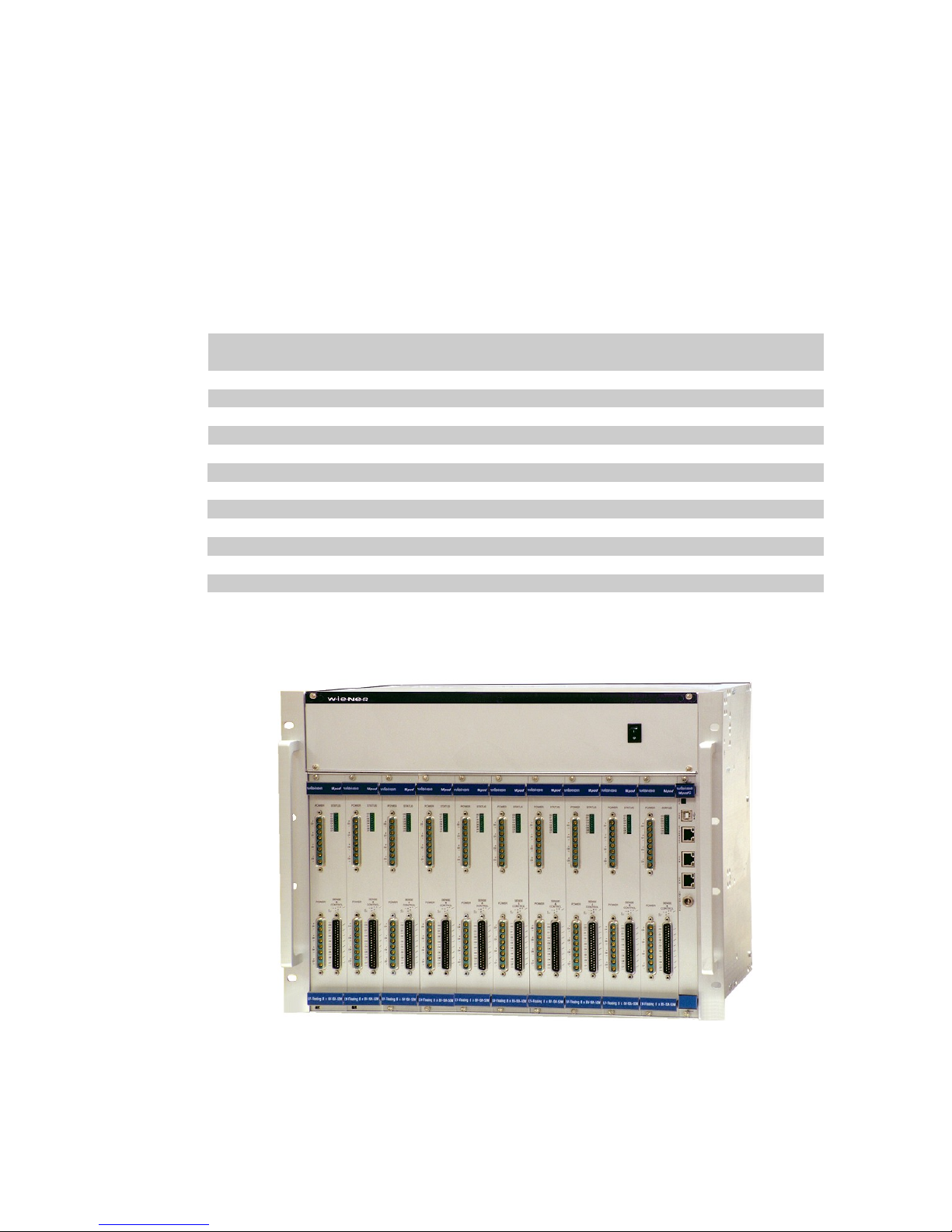
Mpod EC-LV crate with low voltage modules
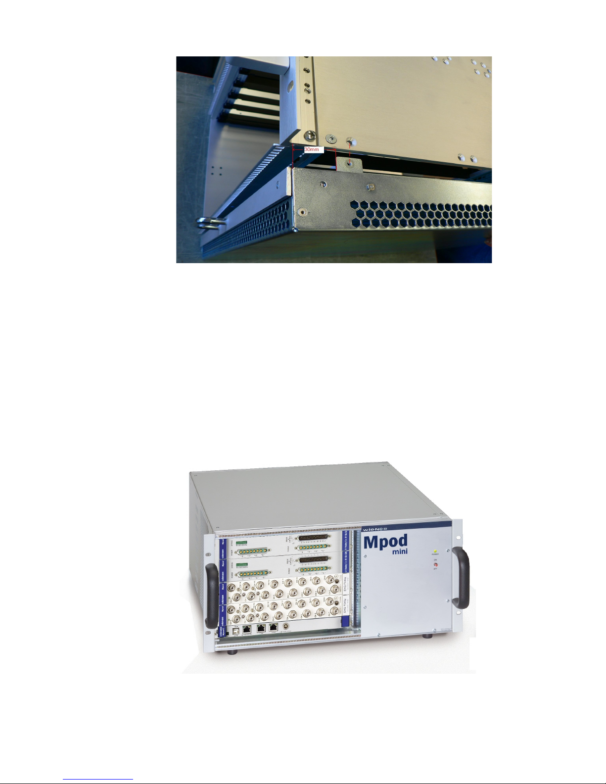
Optionally, Mpod can be outfitted with a removable 1U tray for frontal air inlet and air filter
underneath the bin, as in the picture:
25. July 2012 2 Version 2.5.5
1.3 Mpod Mini crate
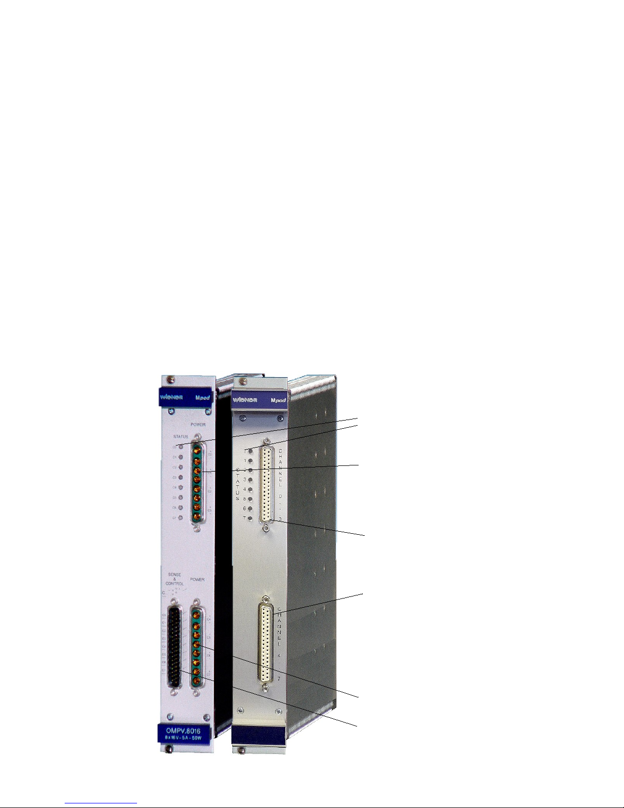
The WIENER Mpod mini crate represents a compact 19” rack mountable chassis for up to 4
Mpod low and high voltage modules. The Mpod mini crate includes the primary power supply
with 600W power for high voltage modules as well as a cooling system with high performance
C fan. It can be outfitted with HV backplane for us as a high voltage system only or with both
HV and LV backplanes.
The first half slot is reserved for the Mpod Controller which manages the primary power
supplies and provides Ethernet, USB and CAN-bus interfaces for remote monitoring and
control. Please note that it is possible to switch the Mpod crate off and on off remotely when
the front panel switch is in ON position.
Mpod Mini crate with Mpod controller and 2 high voltage + 2 low voltage modules
25. July 2012 3 Version 2.5.5
2 LV Modules
The MPV Mpod Low Voltage modules are available with either 4 or 8 channels for different
voltage ranges with 8V, 16V, 30V, 60V maximum respectively. Special modules with up to
120V are under development.
All MVP modules have the following features:
●6U height, 220mm deep fully shielded mechanics
●All C outputs with individual return lines, individually sensed, floating channel to
channel and channel to chassis ground (125V, 500V tested)
●Low noise and ripple
●Voltage and current settings / monitoring for each channel, 15 bit resolution, accuracy
+/-0.1% of full scale value
●Current monitoring and limiting for each channel, 15 bit resolution, accuracy +/-0.05%
of full scale value
●high stability, 0.2%/10k
●Programmable channel parameters:
○voltage, under voltage / over voltage trip point
○current limit
○power, regulation type, internal / externl sense
○ramping speed up and down (1V/s … 500V/s)
○group features / error handling
●programming and monitoring via Ethernet (TCP/IP) and USB
●Connectors: 2 x 8 pin high current sub- , 37 pin sub- for sense / control or
2 x 37 pin sub- for C and sense (4 channels each)
25. July 2012 4 Version 2.5.5
C terminal channel 4 to 7
C terminal channel 0 to 3
Sense and Control terminal
C terminal and sense
channel 0 to 3
C terminal and sense
channel 4 to 7
Status LE 's for all 8
channels
Questo manuale è adatto per i seguenti modelli
1
Indice
Altri manuali Wiener Alimentazione elettrica


