WiT VL53L1 Manuale utente

2
Tutorial Link
Google Drive
Link to instructions DEMO:
WITMOTION Youtube Channel
If you have technical problems or cannot find the information that you need in the
provided documents, please contact our support team. Our engineering team is
committed to providing the required support necessary to ensure that you are
successful with the operation of our AHRS sensors.
Contact
Technical Support Contact Info
Application
●Robot
●UAV
●Intelligent Device

3
Contents
Tutorial Link..........................................................................................2
Contact ................................................................................................2
Application............................................................................................2
Contents ..............................................................................................3
1Overview.........................................................................................4
2Product Size ....................................................................................5
3Parameter .......................................................................................6
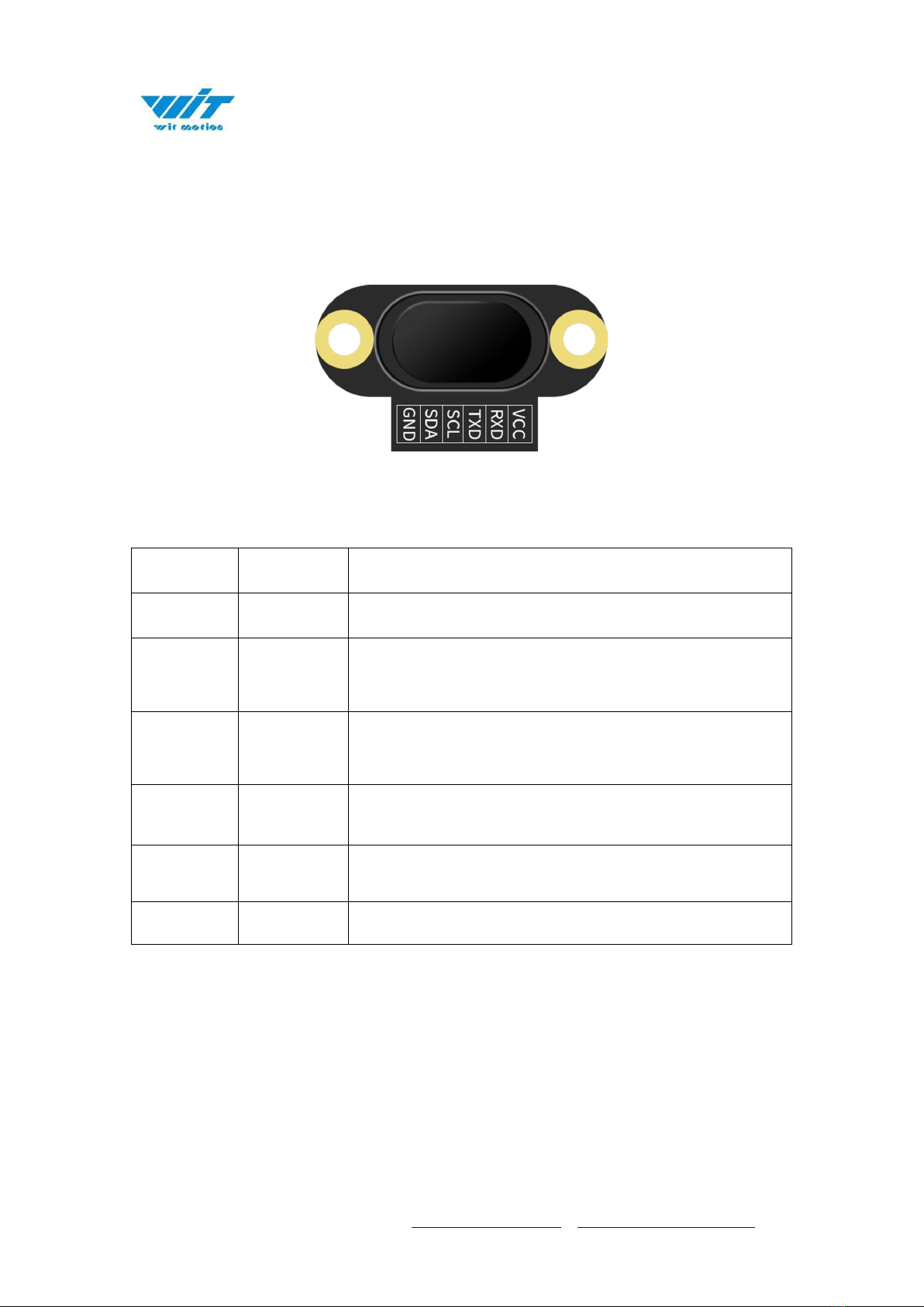
4Pin Instruction..................................................................................7
5Hardware Connection ........................................................................8
5.1
PC Connection ..........................................................................8
5.2
IIC Connection .........................................................................9
6Use Instructions with PC ..................................................................11
6.1
Serial Connection....................................................................11
6.2
Data View ..............................................................................13
6.3
ID ........................................................................................14
6.4
Reset ....................................................................................15
6.5
Baud Rate..............................................................................16
6.6
Return Rate ...........................................................................17
6.7
Calibration Module ..................................................................18
6.8
Measurement Mode .................................................................19
7Communication Protocol ..................................................................21
7.1
Serial Mode............................................................................21
7.2
Modbus Protocol .....................................................................22
7.3
Modbus Register .....................................................................24
7.4
IIC Mode ...............................................................................27

4
1Overview
⚫With voltage stabilization circuit, working voltage 3.3V~5V, compatible
with 3.3V embedded system.
⚫Supports serial, Modbus, and IIC modes.
⚫Two kinds of digital interface serial port and IIC, IIC is directly
connected to the chip.
⚫Data output rate up to 100Hz. 0.1~100Hz (default 100Hz) can be
adjusted.
⚫2-layer PCB board process, thinner, smaller and more reliable. Metal
shielding cover to prevent static interference.
⚫Default short-distance mode (the longest measurement distance is 2
meters), when measuring 4 meters, change to the long-distance mode.

Parameter
Specification
➢Voltage
3.3V-5V
➢Current
<33mA
➢Size
20mm x13mm x6.2mm
0.787" x 0.511" x0.244"
➢Fixed Hole
Spacing 16mm, hole radius 1mm
Spacing 0.630", hole radius 0.039"
➢Return Rate
0.1~100HZ(default 10Hz)
➢Measuring Distance
40mm-4000mm (4000mm without optical cover)
1.575"-157.480" (157.480"without optical cover)
➢Interface
Level TTL
➢Baud Rate
Supports 2400-921600, default 115200
➢Ranging Error
±20mm (±0.787")

7
4Pin Instruction
Pin Explanation
Number
Pin
Explanation
1
VCC
3.3V-5.0V power output
2
RXD
Serial port receiving pin
(TTL level, not directly connected to RS232 level)
can be connected to the TXD of the microcontroller
3
TXD
Serial port sending pin
(TT level, not directly connected to RS232 level)
can be connected to the RXD of the microcontroller
4
SCL
IIC communication clock pin
(need to enter IIC mode)
5
SDA
IIC communication data pin
(need to enter IIC mode)
6
GND
Ground

8
5Hardware Connection
5.1
PC Connection
To connect with a computer, a serial port module with USB to TTL level is
required. We recommend the following two USB to serial modules:
3-in-1 serial converter 6-in-1 serial converter
Step 1. Connect the sensor with a serial converter
PIN Connection:
VCC - 5V
TX - RX
RX - TX
GND –GND
Step 2. Plug it into computer.
PC-serial module connection diagram:

10
Notice:
1. The sensor and the measured object should be as parallel as possible. If there
is a deviation, the angle cannot be greater than the laser emission angle.
2. To detect fast-moving objects, the sampling frequency should be adjusted
(VL53L1 sets the timing preset time and measurement time interval).
3. The laser light source is an invisible beam to the naked eye (the laser can be
seen with a mobile phone camera). Obstacles in the emission angle of the light
source will affect the ranging effect.
4. The module is affected by natural light. In general, the stronger the natural
light, the greater the impact. That is, the ranging distance becomes shorter, the
accuracy becomes worse, and the fluctuation becomes larger. Under strong light
(such as sunlight), it is generally recommended to be used in close-range
detection scenarios.
Indice
Altri manuali WiT Sensore di sicurezza


