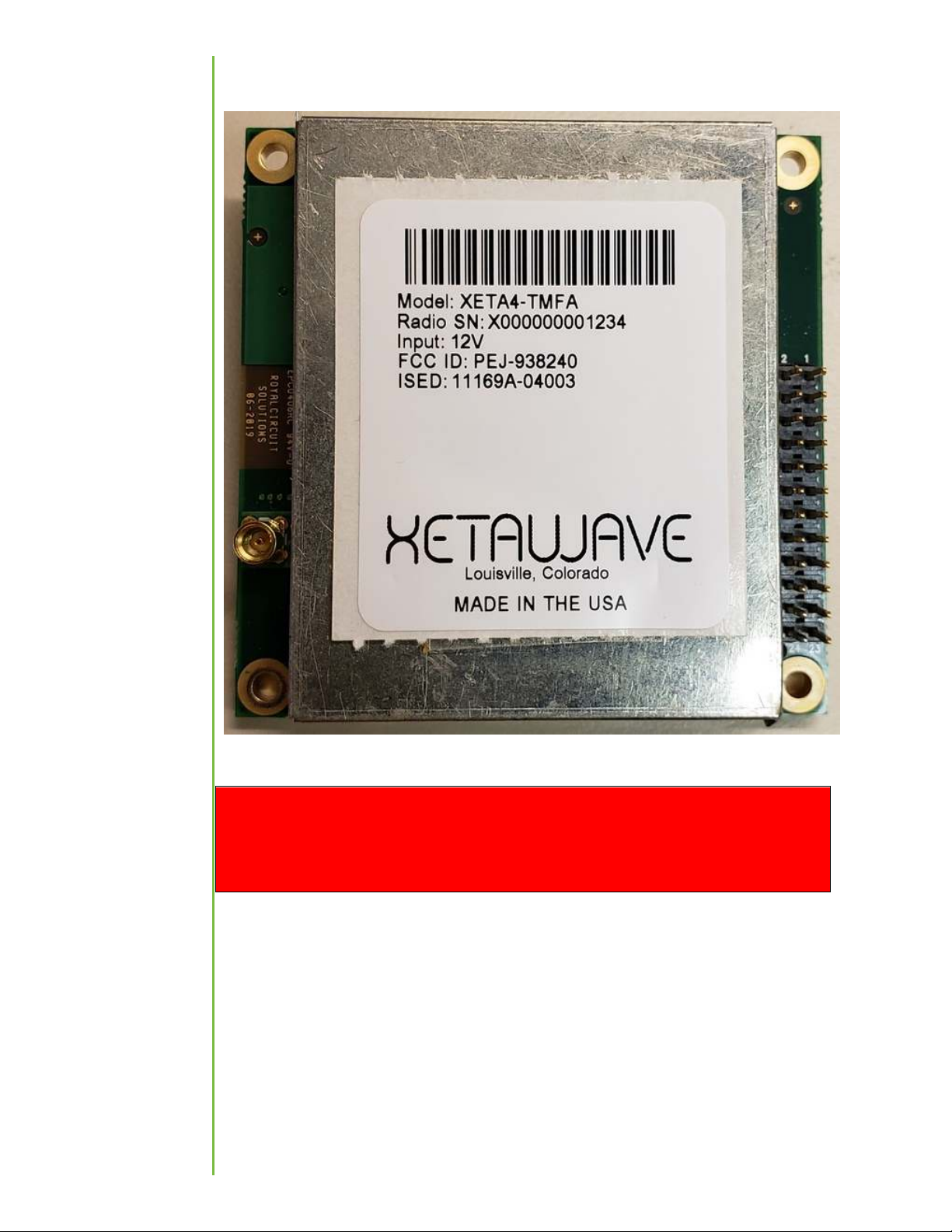
Xetawave XETA4-TMFA Manuale utente

XETA4-TMFA
User Manual
Rev. B

i
Warranty ............................................................................................................................. 1
FCC Notifications .................................................................................................................
Federal Communications Commission ...........................................................................
Integration FCC ID ...........................................................................................................
FCC Antenna Compliance ................................................................................................ 4
FCC Exposure Compliance ............................................................................................... 4
FCC MPE Calculation ....................................................................................................... 5
Industry Canada .................................................................................................................. 5
IC ..................................................................................................................................... 5
IC Setting ......................................................................................................................... 6
IC Exposure Compliance .............................................................................................. 7
Industry Canada Antenna Compliance ....................................................................... 8
Configuration ...................................................................................................................... 8
Password Protection ....................................................................................................... 8
Communicating with the XETA4-TMFA ............................................................................... 8
The Diag Port .................................................................................................................. 8
Operating Menu ............................................................................................................ 10
Configuration/Utilities Menu ........................................................................................ 10
Serial Port Configuration ............................................................................................... 11
Baud Rate .................................................................................................................. 1
Data Serial Framing ................................................................................................... 13
RF Configuration ........................................................................................................... 13
Maximum Separation................................................................................................ 14
RF Transmit Power (“MAS transmit power”) ............................................................ 14
Master Transmit Frequency (“MAS master transmit frequency”) ........................... 15
Slave Transmit Frequency (“MAS slave transmit frequency”) .................................. 15
Table of
Contents

1
XetaWave LLC warrants your XetaWave wireless data transceiver against defects in
materials and manufacturing for a period of two years from the date of purchase. In the
event of a product failure due to materials or workmanship, XetaWave will, at its
discretion, repair or replace the product.
In no event, will XetaWave LLC, its suppliers or its licensors, be liable for any damages
arising from the use of or the inability to use this product. This includes business
interruption, loss of business information, or other loss which may arise from the use of
this product. XetaWave LLC transceivers should not be used in situations where failure
to transmit or receive data could result in damage of any kind to the user or any other
party, including but not limited to personal injury, death, or loss of property. XetaWave
LLC accepts no responsibility for damages of any kind resulting from delays or errors in
data transmitted or received using the XetaWave transceiver, or for the failure of such
transceiver to transmit or receive such data.
Warranty policy may not apply:
1) If product repair, adjustments, or parts replacements is required due to
accident, neglect or unusual physical, electrical or electromagnetic stress.
) If product is used outside of XetaWave specifications.
3) If product has been modified, repaired or altered by Customer unless XetaWave
specifically authorized such alterations in each instance in writing.
The warranty period begins from the date of shipment and is defined per the standard
warranty policy stated above.
Information in this document is subject to change without notice. The information
contained in this document is proprietary and confidential to XetaWave LLC. This
manual is for use by purchasers and other authorized users of the XetaWave wireless
data transceiver only.
No part of this document may be reproduced or transmitted in any form or by any
means, electronic or mechanical, or for any purpose without the express written
permission of XetaWave LLC.
This product is licensed by the United States. Diversion contrary to U.S. law is
prohibited. Shipment or re-export of this product outside of the United States may
require authorization by the U.S. Bureau of Export Administration. Please contact
XetaWave LLC for assistance and further information.
Warranty


Federal Communications Commission
This device complies with Title 47 CFR
Part 90 of the federal code. The device complies
with 47CFR § 1.1310, Table 1, Limits for General Population/Uncontrolled Exposure for
MPE (maximum permissible exposure) to electromagnetic fields, when installed and
operated as described herein.
This device must be operated as supplied by XetaWave LLC. Any changes or
modifications made to the device without the express written approval of XetaWave LLC
will void the user’s authority to operate the device, and may result in regulatory
violations and liabilities.
Caution
The Xeta4-TMFA has a maximum transmitted output power of 10 watts
when used in
compliance with FCC regulations in the 450-470 MHz frequency bands. The transmit
antenna shall be kept at least 187 cm from physical space where humans may exist,
based on a maximum antenna gain of 11. dBi.
See FCC Exposure Compliance on page 4 for more details and RF exposure
calculations.
These limits are designed to provide reasonable protection against harmful energy and,
if not installed and used in accordance with the instructions, may result in human
exposure to excessive RF energy.
This device must be installed in a host unit provided by XetaWave, LLC for fixed
installations.
Integration FCC ID
When the module is installed inside another device, the outside of the device into which
the module is installed must display a label referring to the enclosed module.
The exterior label shall use the wording: ‘Contains FCC ID: PEJ-938 40’.
FCC
Notifications

3
WARNING
This radio module shall be installed by an RF/radio professional familiar with the
applicable rules. Installation of antennas shall be performed in a manner that will
provide at least the MPE Distance from any user or member of the public in the
direction of maximum radiation.
Professional installers receive radios with factory preset settings in compliance with the
values and limits specified in the radio certification.
While the grant may reference the full range of 450-470 MHz frequencies, we attest
that this product will comply with Part 90 FCC regulations within the following
frequency bands and modulations:
450 - 454 MHz
456 – 46 .5375 MHz

4
46 .7375 – 467.5375 MHz
467.7375 – 470 MHz
FCC Antenna Compliance
Since professional installation is required, standard RF connectors are used. Adapters or
custom coaxial cables may be required to connect the radio’s RF connector to the
desired antenna.
Any antenna from a reputable manufacturer with desired bandwidth, gain/pattern
coverage, and a rated nominal impedance of 50 ohms, can be used.
FCC Exposure Compliance
FCC ID PEJ-938 40
It is the responsibility of the licensee or user to guarantee compliance with the
appropriate MPE regulations when operating this device in a way other than described
herein. The installer of this equipment must ensure the antenna is located or oriented
such that it does not emit an RF field in excess of the guidelines in FCC OET Bulletin 65
and 47CFR § 1.1310.
People should not be near the antenna when the radio link is operating as general
practice and maintain a safe distance as calculated below.
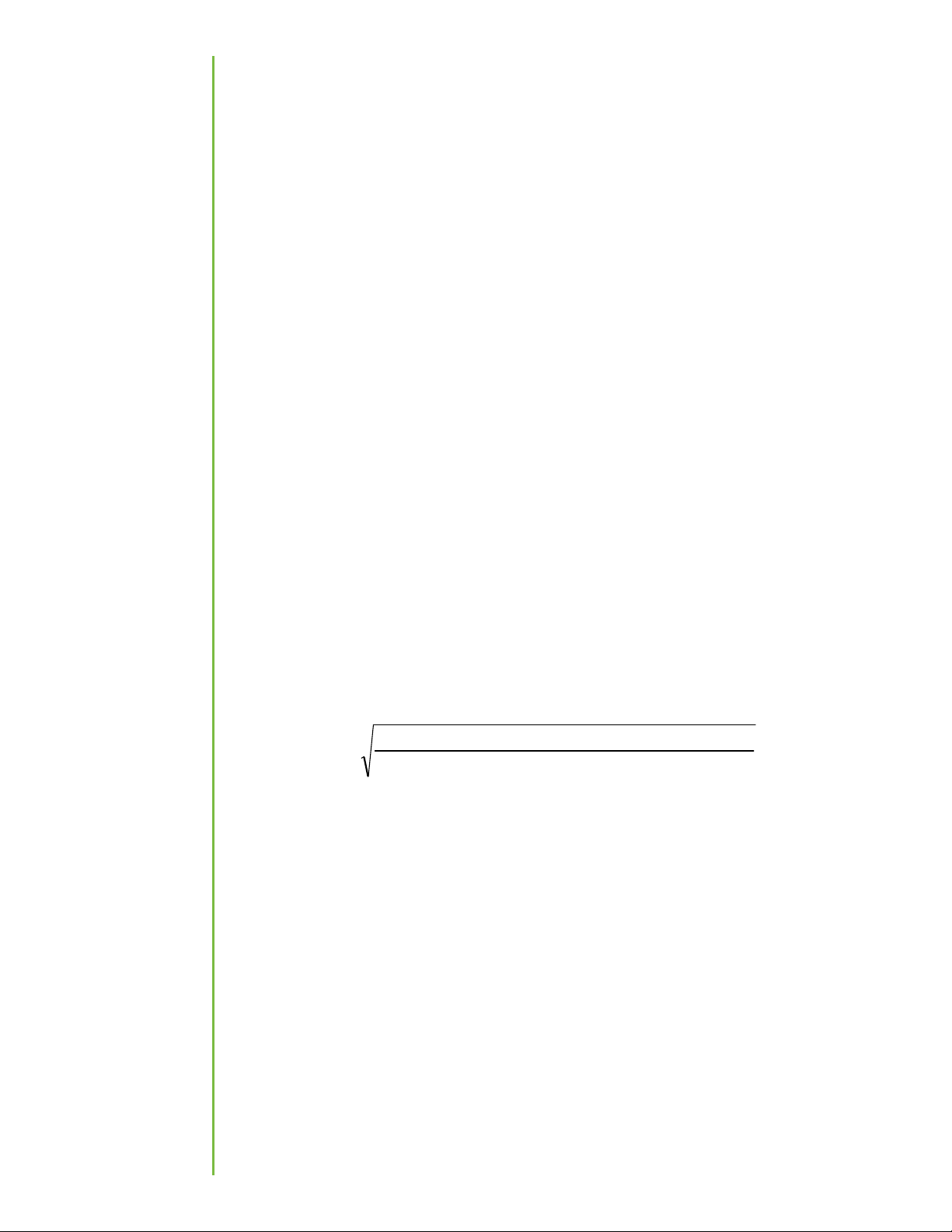
The MPED (Maximum Permissible Exposure Distance) is calculated using the FCC limit
for a general population/uncontrolled exposure in the 450 - 470 MHz frequency band.
To calculate safe distance:
(
)
(
)
(
)
( )( )
mitExposureLi
nAntennaGaiDutyCycleowerConductedP
MPED
π
4
=
Where:
MPED is Maximum Permissible Exposure Distance or safe distance in cm;
ConductedPower is the power delivered to the antenna in mW;
ExposureLimit is the limit for General Population/ Uncontrolled exposure in mW/cm
All quantities are calculated in linear or numeric quantities.
The XETA4-TMFA transmitter duty cycle varies depending on many factors. Packet sizes,
which are set up by the installer as part of the radio/network configuration, are a
primary determinant. At power up and with no data payload, the radios will transmit a
beacon with a duty cycle of 6 to 10%, depending upon modulation setting. The duty
cycle will increase when a data payload is transmitted, but will also be influenced by
network configuration, network type, number of radios in the network, propagation

5
delay between radios, and other factors. For the purpose of the MPED calculation, a
worst case duty cycle of 100% will be assumed, although this duty cycle is not achieved
in typical operation.
Integrators are responsible for including RF exposure information statements in their
final user manuals.
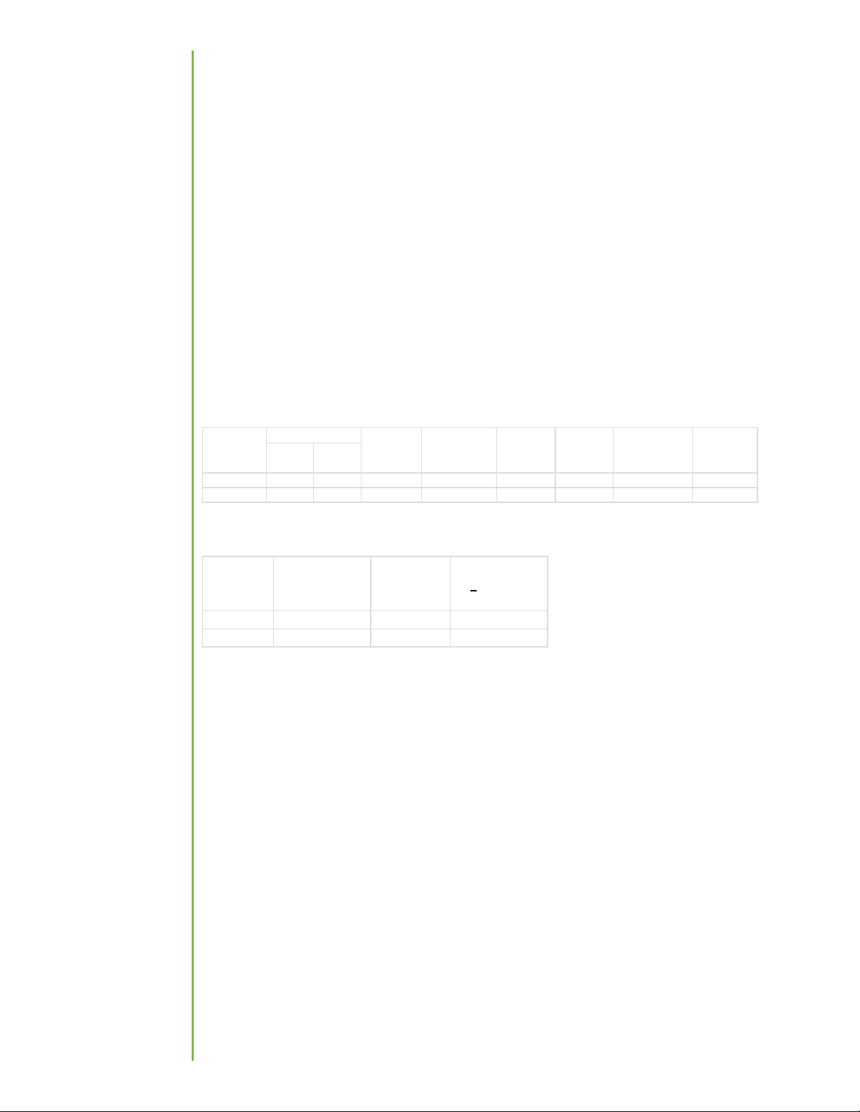
The worst case MPED for any transmit frequency in the 450 - 470 MHz band is shown in
the table in the following section.
FCC MPE Calculation
Use: General
Antenna: 11. dBi
For 450-470 MHz single transmitters (for general population/uncontrolled exposure)
The worst case required separation distance in the US is 187 cm (at 450 MHz).
For the cases where S > the MPE Limit
IC
IC 11169A-04003
This device complies with Industry Canada’s license-exempt RSSs. Operation is subject
to the following two conditions:
(1) This device may not cause interference; and
( ) This device must accept any interference, including interference that may cause
undesired operation of the device.
Le present appareil est conforme aux CNR d’Industrie Canada applicables aux appareils
radio exempts de license. L’exploitation est autorisée aux deux conditions suivantes:
(1) l’appareil ne doit pas produire de brouillage; et
mW
dBm
450.0 10000 40.0 0.0 11. 40.0 1318 6 6. 3 0.300
470.0 10000 40.0 0.0 11. 40.0 1318 6 6. 3 0.313
Power Density
(S) at 0 cm,
mW/cm^
MPE Limit at
0 cm,
mW/cm^
EUT Power
Frequency,
MHz
Cable Loss,
dB
Antenna Gain,
dBi
Power at
Antenna,
dBm
EIRP, mW
Frequency,
MHz
Power Density
(S) at 0 cm,
mW/cm^
MPE Limit at
0 cm,
mW/cm^
Distance where
S < MPE Limit,
cm
450.0 6. 3 0.300 187.0
470.0 6. 3 0.313 183.0
Industry
Canada

6
( ) l’utilisateur de l’appareil doit accepter tout brouillage radioélectrique subi,
même si le brouillage est susceptible d’en compromettre le fonctionnement.
This device must be operated as supplied by XetaWave LLC. Any changes or
modifications made to the device without the express written approval of XetaWave LLC
may void the user’s authority to operate the device.
Cet appareil doit être utilisé comme fourni par XetaWave LLC. Toute modification
apportée à l'appareil sans l'autorisation écrite expresse de XetaWave LLC peut annuler
l'autorisation de l'utilisateur d'utiliser l'appareil.
In compliance with CTFA 018, users are restricted from setting the device to the
following frequency bands:
En conformité avec CTFA 018, les utilisateurs sont limités à la configuration de l'appareil
aux bandes de fréquences suivantes:
406.1 – 430 MHz
450 – 470 MHz
IC Setting
This equipment has been tested and found to comply with the limits for a Class B digital
device, pursuant to IC ICES-003.
This unit must be installed in a fixed location.
Cet équipement a été testé et reconnu conforme aux limites d'un appareil numérique
de classe B, conformément au IC ICES-003.
Cet appareil doit être installé dans un endroit fixe.
Integrators are responsible for including RF exposure information statements in their
final user manuals.
Les intégrateurs sont responsables d'inclure des instructions d'information sur la RF
dans leurs manuels d'utilisation.
When the module is installed inside another device, the outside of the device into which
the module is installed must display a label referring to the enclosed module.
The exterior label will use the wording: ‘Contains IC: 11169A-04003’.
HVIN: XETA4-TMFA
Lorsque le module est installé à l'intérieur d'un autre périphérique, l'extérieur du
périphérique dans lequel le module est installé doit afficher une étiquette faisant
référence au module inclus.

7
L'étiquette extérieure utilisera le libellé: 'Contient IC: 11169A-04003’.
HVIN: XETA4-TMFA
IC Exposure Compliance
NOTE: Integrators are required to include RF exposure information in their product
user manual.
REMARQUE: Les intégrateurs doivent inclure les informations d'exposition RF dans
leur manuel utilisateur.
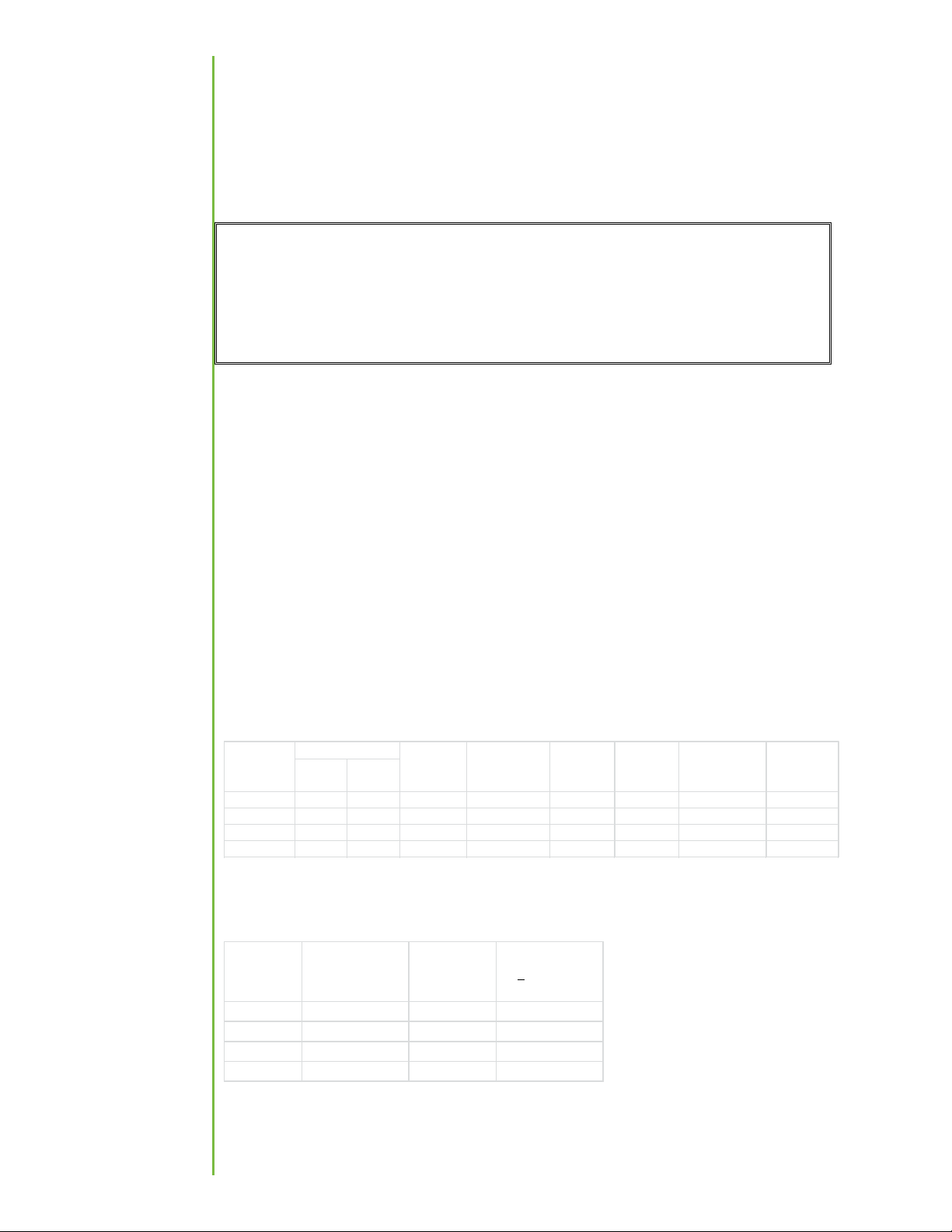
Innovation, Science and Economic Development Canada MPE Calculation
Required separation distance for Canada is 57 cm.
Innovation, Science and Economic Development Canada MPE Calculation
Innovation, science et développement économique Canada Calcul MPE
La distance de séparation requise pour le Canada est de 57 cm.
Innovation, science et développement économique Canada Calcul MPE
Use: General
Utilisation: Généralités
Antenna: 11. dBi
Antenne: 11. dBi
For 406.1 - 470 MHz single transmitters (General use):
Pour émetteurs simples 406.1 - 470 MHz (usage général):
For the cases where S > the MPE Limit:
Pour les cas où S> la limite MPE:
mW
dBm
406.1 10000 40.0 0.0 11. 40.0 1318 6 6 .3 1.59
430.0 10000 40.0 0.0 11. 40.0 1318 6 6 .3 1.65
450.0 10000 40.0 0.0 11. 40.0 1318 6 6 .3 1.70
470.0 10000 40.0 0.0 11. 40.0 1318 6 6 .3 1.75
Frequency,
MHz
EUT Power
Cable Loss,
dB
Antenna Gain,
dBi
Power at
Antenna,
dBm
EIRP, mW
Power Density
(S) at 0 cm,
W/m^
MPE Limit at
0 cm,
W/m^
Frequency,
MHz
Power Density
(S) at 0 cm,
W/m^
MPE Limit at
0 cm,
W/m^
Distance where
S < MPE Limit,
cm
406.1 6 .3 1.59 57.0
430.0 6 .3 1.65 5 .0
450.0 6 .3 1.70 48.
470.0 6 .3 1.75 44.5

8
Industry Canada Antenna Compliance
The antenna used for this radio must be properly installed and maintained and must
provide a separation distance of at least 57 cm (101 inches) from all persons and must
not be collocated or operated in conjunction with any other antenna or transmitter.
Never transmit if any person is closer than the specified distance to the antenna.
L’antenne utilisée pour cette radio doit être correctement installée et entretenue. Elle
doit respecter une distance minimum de 57 cm (101 pouces) de l’ulitisateur et ne doit
pas être installée à proximité ou utilisée conjointement avec tout autre antenne ou
émetteur. N’utilisez pas votre radio si vous ne respectez pas la distance spécifiée.
Password Protection
All radios are shipped from the factory password-protected and do not allow users to
set parameters outside the limits of certification. The method of password entry is
hidden from the user, and the required password for each radio is generated using a
unique mathematical calculation that is proprietary to XetaWave, LLC.
Users have the ability to set parameters, via the Diag port, within the permissible limits.
Users do not have access to programming capability.
The Diag Port
The Diag port is used to configure the Xeta4-TMFA and monitor radio and network
operation, data throughput, and packet error rate. Typically, the Diag port is connected
to a computer or other user equipment with an RS- 3 type interface and ASCII text
display capability. The user’s RS- 3 interface may be a native serial port, or it may be
implemented via an interface converter (for example, a USB-to-RS- 3 converter
dongle). A 3.3 volt to RS- 3 level converter must be used between the radio and the
user’s serial port if the user’s serial port requires standard RS- 3 levels (typically -5
volts/+5 volts to -1 volts/+1 volts). The radio Diag port levels are 0 volts/+3.3 volts,
and it is inverted with respect to standard RS- 3 signaling.
The user’s serial port must be configured to match the following configuration to
communicate:
Bits per Second (Baud): 115 00
Data Bits: 8
Parity: None
Stop Bits: 1
Flow Control: None
Configuration
Communicating
with the
XETA4-TMFA
Indice