XIEGU X6100 Manuale utente

1
X6100, an ultra-portable short-wave transceiver that adopts high-performing SDR software radio platform
architecture, powerful baseband and RF units, transmitting and receiving separated dual-channel structure
and 24bit sampling and large dynamic RF front-end unit, can obtain extremely high radio transmitting and
receiving indicators.
The whole device integrates rich and varied operation functions and desktop-like functions, such as
recording call, variable bandwidth digital filter, digital noise reduction and so on, which brings you a new
cognition and experience on amateur radio. With its compact structure and appearance, you can immediately
set forth on a journey with it, get close to nature, and enjoy the fun of outdoor communication.
● HF/50MHZ full mode (supporting data communication)
● Transmitting power: external power supply: 10W, battery: 5W
● 4-cun high-resolution color screen (800*480)
● Built-in large capacity lithium battery pack (3000mAh, 12V)
● Built-in efficient automatic antenna tuner
● Integrated standing wave scanner and voice pager
● Integrated modem, preset message, CW automatic call
● Built-in Bluetooth/WLAN function, which can realize wireless audio, keyboard and mouse operation
● Integrated USB line control/transmission, supporting USBHOST.
● Standard high-stability TCX0 internal clock source
We strongly recommend you to read through this Manual to rapidly keep abreast of the operation & control
method of the X6100 before using it.
2
Safety Precautions
Do not use this device in lightning weather. Disconnect the power supply and antenna in advance.
Do not touch the antenna during the transmission of the device.
Do not apply AC power to the DC interface on the side panel of transceiver. Otherwise it may cause fire or
damages to the device.
Do not apply more than 15VDC voltage to the DC interface on the side panel of transceiver. Otherwise it may
cause fire or damages to the device.
Do not reverse the polarity of the power cable. Otherwise it may cause fire or damages to the device.
Do not operate or touch the device with wet hands. Otherwise it may cause electric shock or damages to the device.
In case of smoke or peculiar smell, cut off the power supply immediately, remove the power cable, and then contact
the supplier.
Do not use the device in areas, vehicles or aircraft where it is prohibited.
Do not use this device while driving or operating engineering equipment.
Do not use the device in petrol stations, gas stations or the place with combustible gas around.
Do not use the device in hospitals or in an environment where people wear medical devices.
Do not expose the device to rain, snow or any liquid. Otherwise it may cause damages to the device.
Do not use headphones at high volume.
Do not disassemble or modify the device.
Do not place the device near the heat source or in direct sunlight.
Do not place the device in a dusty or damp place.
Do not place the device in a poorly ventilated place and do not block any radiator on the device. Otherwise, the
deceive may be damaged due to overheating.
Do not wipe the device with organic solvents, such as benzene or alcohol. This may damage the surface of the
equipment.
Do not apply impact force on the device. Otherwise it may cause fire or damages to the device.
Do not place the device in the area with temperature range beyond -10°C~+55°C.
Cut off the power supply and remove the external power cable if the device is not used for a long time.

3
Battery Precautions
This device contains lithium-ion battery components, so improper use may result in dangers such as smoke,
fire or battery rupture.
■ The battery pack is installed inside the backplane of the equipment. Do not hit the backplane of the
device.
■ Do not place the device in a place where the temperature is higher than 60°C; otherwise, the battery
pack may rupture or catch fire.
■ Do not place the back of the device near heat sources, such as stove fire or direct sunlight.
■ Do not weld, disassemble or modify battery components by your won. This can lead to protection
failure and battery damage, which can further lead to fire and other hazards.
■ In case of obvious deformation, seepage or peculiar smell at the installation place of the battery pack,
the device shall not be further used, and distributor shall be contacted immediately for assistance.
■ Do not use the device beyond its temperature range; otherwise, the service life of the device and
battery pack may be reduced or damaged.
■ Do not leave the battery pack in fully charged or fully discharged state for a long time. Otherwise, the
service life of battery pack will be shortened. Please maintain the electric quantity of battery pack within
40%~50% if the device is to be left unused for a long time, and then keep it properly.
■ The service life of the built-in battery pack is about 3~4 years generally. Please replace the battery
pack once its service life reaches this period. Even if the battery still works, its performance will be
significantly reduced and service time will be greatly shortened. The battery pack can be generally charged
and discharged for 300~500 times. This depends on specific usage conditions.
■ Do not charge the device with other non-compliant chargers.
■ Pay attention to the condition of the device when charging. Stop charging immediately in case of any
abnormality.
■ Do not charge the device in vehicles under direct sunlight.
Important Note
■ Make sure you have had relevant operating certificates or permissions before making a call on the
frequency band of amateur radio.
■ Make sure the antenna feed system meets the transmitting requirements before actual transmitting.
■ The device may be hot after continuous and long-term transmitting (such as FT8 operation). Please
appropriately extend transmitting interval and strengthen external heat dissipation.
■ Please place the device in a safe and reliable place and keep it away from children or unauthorized
persons.
Electromagnetic Interference
It shall be noted when using wireless LAN or Bluetooth devices that when other wireless devices, such as
wireless mouse, wireless keyboard and wireless router, work in the same frequency band, they may interfere
with each other, resulting in unstable or interrupted connection of the device. In such case, please keep
away from other devices or stop using those devices.

4
I. Panel Instructions
Front panel
1 GEN button 9 DFL button
Press it to bring up the general settings menu. Press it to bring up digital filter settings interface
2 KEY button 10~14 Multi-function button
Press it to bring up tapper settings menu. Press it to execute functions displayed on screen.
3 DFN button 15 Main knob
Press it to bring up the menu of digital functions. Rotate it to adjust frequency.
4 MFK multi-function knob 16 Lock button
Default: Long press for 1s to lock the keys operation on panel.
Customize: Long press for 1s again to unlock.
5 VOL/SQL/RFG knob 17 Power supply/TR indication
Default: volume control. The indicator light is green after startup.
Press the knob to adjust SQL muting depth.
Press the knob again to adjust RFG gain.
6 Power button
Press and hold it to turn on the power supply
of
transceiver.
Press and hold it for 1s to turn off the power supply
of
transceiver.
7 APP button
Press it to bring up function menu.
8 MSG button
Press it to bring up information editing and storage
interface.
When the transceiver is in transmitting state, the indicator light
is red.

5
Left plate
18 ANT
BNC interface, 50Ω, for antenna connection.
19 I/Q OUT
IQ signal output port 3.5mm stereo socket.
20 DC IN
External power input port, 5525 type.
Note: input voltage shall not be higher than 15V DC.
Right plate
21 CARD
microSD memory card slot
22 DEV
USB port. Slave interface
23 HOST
USB port. Host interface.
24 S/P
External speaker/headphone interface, with
speaker or headphone output can be set via menu.
It is a 3.5mm stereo interface achieving stereo
output.
Note: short circuit or silence will be caused
if
plugging the single track plug externally.
25 KEY
It is a 3.5mm stereo interface used to connect
manual/auto tapper. See page 8 for connection.
26 ACC
It is a 3.5mm stereo interface. See page 8 for
interface definitions.
27 MIC
Hand microphone interface. The interface is
of
type RJ45.

6
Top button
28 PTT
PTT button on device body.
29 AM|FM
AM/FM mode switch button.
30 CW
CW mode switch button
31 SSB
SSB mode switch button
32 V/M
VF0/MEM0 status switch
33 AGC
AGC switch/speed selection button
34 FST
Fast step selection button
35 ATU
Built-in antenna tuner access/tuning button
36 PRE
Pre-amplifier/pre-attenuator switch
37 A/B
VF0A-VF0B switch button
38~39 Left and right switch
Frequency band/channel increase and decrease switch

7
Hand microphone button
1. LOCK button Lock button
2. PTT button Transmitting control button
3. Up/down Frequency increase/decrease button (user-defined, detailed in system
menu 1)
4. Transceiver indicator light Hand microphone operation indicator light
5. Figure button area Figure keyboard area
6. FIL button Filter selection
7. MODE button Selection of working mode of host
8. Functional indicator light No
9. Function button F1/F2 key (user-defined, detailed in system menu 2&3)
10. MW button Memory operation
11. V/M button Frequency/channel switching
12. XFC button No function temporarily
13. TUNER button Long press to start antenna automatic tuning

8
Interface Definition
Microphone port Definition of ACC interface
Connection of S/P Port Definition of I/Q OUT interface
Connection of KEY Port
Connect manual/automatic tapper according to
the schematic diagram shown in the right figure.
Note :
● If the connector of the manual tapper is a
6.5mm 2-core plug, please change it to a 3-core
3.5mm stereo plug according to the wiring
method shown in the right figure, and connect the
trigger end of the electric key to the "Di" or "Da"
terminal.
●Take care that direct use of the 2-core to
3-core adapter or incorrect wiring may result
the radio in CW transmission status all the
time.
●Using plugs of other specifications may damage the socket.
● X6100 may switch to transmitting mode if plugging in or unplugging the tapper plug when it is
working.
● Please cut off the power supply of X6100 before connecting or disconnecting the tapper.
Di
Di
Da
Da Com
mon
Com
mon

9
Power source wiring
13.8V external DC power supply can be used for X6100. The current load capacity of DC power supply
shall be at least 3.5A. Attached power lines can be used to connect to radio and DC power supply.
DC power supply shall be connected in strict accordance with following figure to avoid reverse polarity
connection.
■ EMC magnet ring can be applied on power lines to prevent external disturbance from entering radio
via power lines and radio-frequency interference in radio from radiating externally via power lines when
external power supply is adopted for X6100. Magnet ring shall be installed at the side closing to radio to
greatest extent.
Charging
The X6100 radio shall be charged by the attached charging adapter. The radio can be charged by
connecting the AC end of charging adapter with electric supply and inserting the output end into the DC
interface at the left of X6100.
The host will automatically stop charging once the charge is completed.
Note :
■ Polarity of power lines shall be carefully inspected to avoid reverse polarity connection when external
power supply is adopted.
■ Reverse connection of power may cause severe damage to the radio.
■ Do not charge the radio with any other charger that does not meet the specifications. Otherwise, the
device may be damaged
Caution!
1. The charging adapter can only charge the X6100 and cannot be used for transmitting as there is a risk of
damaging the device.
2. Under no circumstances shall the DC port on the left of the X6100 be connected to a voltage higher than
15VDC. Otherwise, serious device damage may occur.
10
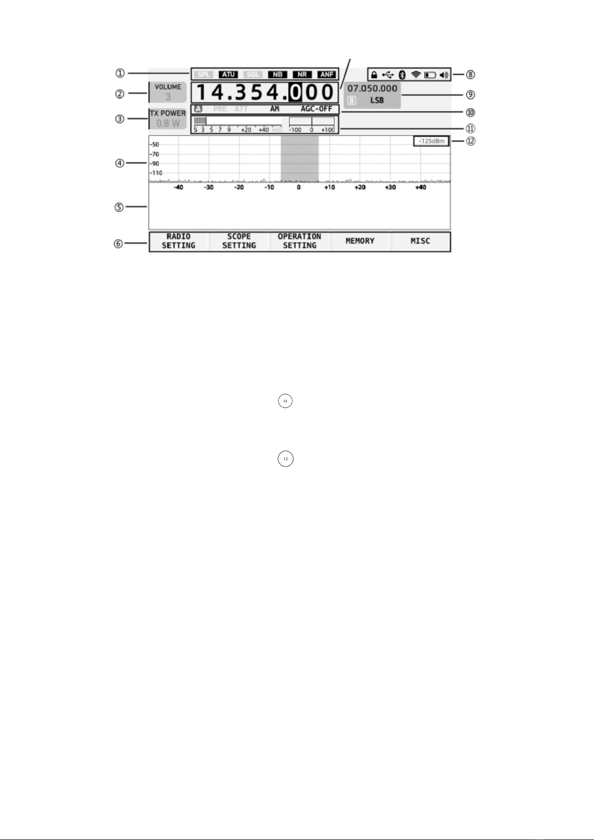
II. Screen Display Interface
①Status display area 1
This area displays SPL, ATU, SQL, NB, NR and
ANF switch status.
②Volume tag
Display volume/noise level/RF gain adjustment.
Short press the volume knob to switch the above
three status.
③Multi-function tag
The figure shows the transmitting power
adjustment tag. Items of the tag displayed can be
rapidly set via menu.
④Spectrum display area
It displays the signal strength of about -122dBm
at minimum
⑤Waterfall plot display area
⑥Multi-function menu area
Short press the corresponding button at the
bottom of the screen to operate corresponding
functions.
⑦Main VFO frequency display area
⑧Status display area 2
This area displays the status including lock/USB
port/Bluetooth/WLAN/battery/volume.
⑨VFOB display area
⑩Status display area 3
This area displays PRE/ATT/mode /AGC status
Table header area
This area displays S table and CW frequency aligned
windows
Signal strength dBm display
Altri manuali per X6100
3
Indice
Altri manuali XIEGU Ricetrasmettitore

XIEGU
XIEGU G90 Manuale utente

XIEGU
XIEGU X108 Manuale utente

XIEGU
XIEGU G106 Manuale utente

XIEGU
XIEGU X1M Pro Manuale utente

XIEGU
XIEGU X5105 Manuale di istruzioni

XIEGU
XIEGU X5105 Manuale utente

XIEGU
XIEGU G90 Manuale utente

XIEGU
XIEGU G90 Manuale utente

XIEGU
XIEGU X108G Manuale utente

XIEGU
XIEGU G90 Manuale utente

XIEGU
XIEGU G106 Manuale utente

XIEGU
XIEGU G1M Manuale utente

XIEGU
XIEGU X5105 Manuale per l'uso e la cura

XIEGU
XIEGU G90 Manuale utente

XIEGU
XIEGU X6100 Manuale utente

XIEGU
XIEGU X108G Manuale utente

XIEGU
XIEGU G1M Manuale utente

XIEGU
XIEGU X5105 Manuale utente

XIEGU
XIEGU X108G Manuale utente

XIEGU
XIEGU X6100 Manuale utente


