Xsens MTi 1 Series Manuale utente

1
www.xsens.com
Development Kit User
Manual
MTi 1-series
Document MT0512P, Revision 2019.A, Dec 2019

2
www.xsens.com
Revision
Date
By
Changes
A
8 July 2015
MHA
Initial release
…
…
…
…
E
25 June 2018
WBO
Added information on PCB versions with
I2C pull-up resistors
F
22 August 2018
SGI
Refer to new embedded examples (MTSS
v4.9.1)
G
16 Jan 2019
SGI
Update Chapter 3 to match GUI of MTSS
2019.0
H
SGI
Added chapter 4.3: Power Supplies
2019.A
Dec 2019
AKO
Xsens brand update
© 2005-2020, Xsens Technologies B.V. All rights reserved. Information in this document is subject to change
without notice. Xsens, Xsens DOT, MVN, MotionGrid, MTi, MTi-G, MTx, MTw, Awinda and KiC are registered
trademarks or trademarks of Xsens Technologies B.V. and/or its parent, subsidiaries and/or affiliates in The
Netherlands, the USA and/or other countries. All other trademarks are the property of their respective owners.

3
www.xsens.com
Table of Contents
1General information ..................................................................5
1.1 Package information ................................................................................... 5
1.2 Ordering information................................................................................... 6
2Introduction.............................................................................. 7
2.1 Kit contents and features ............................................................................ 7
2.2 Software and documentation ....................................................................... 8
2.2.1 Embedded examples ............................................................................. 8
3Getting started.......................................................................... 9
3.1 Installing MT Software Suite ........................................................................ 9
3.2 Displaying data in MT Manager....................................................................10
3.3 Configuring the MTi 1-series .......................................................................11
4Shield board ............................................................................ 13
4.1 Connections and peripheral switch...............................................................13
4.2 Pin descriptions .........................................................................................17
4.3 Power supplies ..........................................................................................17
4.4 Electrical specifications...............................................................................18
4.5 Absolute maximum ratings .........................................................................18
4.6 Package drawing .......................................................................................20
List of Tables
Table 1: Package contents for 1-series Development Kits ........................................... 5
Table 2: Ordering information for 1-series Development Kits ...................................... 6
Table 3: Connections on external power header (J100 in Figure 7) .............................14
Table 4: Connections on Arduino-compatible header (P100, P101, P102 and P103 in
Figure 7) .............................................................................................................14
Table 5: Connections on UART communication extension sockets (P202 and P203 in
Figure 7) .............................................................................................................15
Table 6: Switch positions to enable interfaces on Shield Board (SW200 in Figure 7)......15
Table 7: Connections on auxiliary sensor extension sockets (P200 and P201 in Figure 7)
..........................................................................................................................16
Table 8: Pin descriptions Shield Board.....................................................................17
Table 9: System specification Shield Board ..............................................................18
Table 10: Absolute maximum ratings Shield Board ...................................................18

4
www.xsens.com
List of Figures
Figure 1: Exploded view of the MTi 1-series Shield board............................................ 7
Figure 2: Start up screen for MT Software Suite installer ............................................ 9
Figure 3: Software components installation............................................................... 9
Figure 4: Successful installation screen ...................................................................10
Figure 5: MT Manager overview..............................................................................11
Figure 6: Output configuration dialog in MT Manager using an MTi-7-DK .....................11
Figure 7: MTi 1-series Shield Board with connector designators ..................................13
Figure 8: Top view (left) and the bottom view (right) of the GNSS daughter card .........16
Figure 9: MTi 1-series Shield Board package drawing (Top and Side view) ...................20

5
www.xsens.com
1General information
This document provides information on the contents and usage of the MTi 1-series
Development Kits. The MTi 1-series module (MTi 1-s) is a fully functional, self-contained
module that is easy to design-in. The MTi 1-s can be connected to a host through I2C,
SPI or UART interfaces. The MTi-3 Development Kit (MTi-3-DK) enables users to evaluate
features for the MTi-3 (AHRS), MTi-2 (VRU) and MTi-1 (IMU) modules. The MTi-7
Development Kit (MTi-7-DK) enables users to evaluate features of the MTi-7 (external-
GNSS/INS). In addition to the MTi 1-s interfaces, both Development Kits include a USB
interface.
The MTi 1-series module consists of components that are sensitive to
stress. As a result, sensor characteristics may change when forces are
applied to the module. As each module is calibrated individually, Xsens
cannot guarantee performance after improper handling. It is therefore
recommended not to remove the module from the socket, and to use
the Development Kit for prototyping and evaluation purposes only. For
more information on proper handling, refer to the MTi 1-series
Hardware Integration manual (see Section 2.2).
1.1 Package information
Table 1: Package contents for 1-series Development Kits
Component
Name
Shield board
MTi 1-series module (MTi 1-s)
GNSS daughter card1
1
Only with MTi-7-DK

6
www.xsens.com
GNSS antenna1
USB cable
1.2 Ordering information
Table 2: Ordering information for 1-series Development Kits
Kit
Description
Package contents
Packing Method
MTi-7-DK
Development kit for MTi-7
(external-GNSS-aided-AHRS)
- Shield board
- MTi-7 module (in the socket)
- GNSS daughter card
- GNSS antenna
- USB cable
Single unit
MTi-3-DK
Development kit for MTi-1 (IMU),
MTi-2 (VRU) and MTi-3 (AHRS)
- Shield board
- MTi-3 module (in the socket)
- USB cable
Single unit

7
www.xsens.com
2Introduction
2.1 Kit contents and features
The MTi 1-series Development Kit contains
- Shield board
- MTi-3 or MTi-7 mounted in the socket
- GNSS daughter card (only with MTi-7-DK)
- GNSS antenna (only with MTi-7-DK)
- USB cable
Figure 1: Exploded view of the MTi 1-series Shield board
The Shield Board, the MTi 1-s (orange module) and the GNSS daughter card (with the
SMA connector) are shown in Figure 1. The features of the Shield Board include:
-3.3 V compatible I/O
-Power indicator LEDs
-Arduino-compatible headers
-External power pin header
-Manual peripheral selection switch for MTi 1-series
-Switching between UART and I2C on Arduino-compatible headers based on PSEL
switch setting
-USB to UART converter
-Auxiliary extension socket
-Optional socket connections for mikroBUS™ RS232/RS485 click boards™
See Section 4 for more details.

8
www.xsens.com
2.2 Software and documentation
The MTi 1-series Development Kit is supported by the MT Software Suite, which includes
the following software components:
- MT Manager
- Magnetic Field Mapper
- MT SDK with documentation
Additionally, the latest firmware for the MTi-3 or the MTi-7 module can be downloaded
and updated using the Firmware Updater that is also available on our website.
The Software components can be downloaded from the Xsens website –www.xsens.com.
Along with the SDK documentation that is part of the MT Software Suite installer
package, the MTi 1-series Development Kit is supported by the following additional
documents
2
- Hardware Integration Manual: MTi 1-series (MT1503)
- Datasheet: MTi 1-series (MT0512P)
- MT Low Level Communication Protocol (MT0101P)
- MT Manager User Manual (MT0216P)
- MT Magnetic Field Mapper Documentation (MT0202P)
- Product Change Notification
oMTi 1-series: Components placement change
2.2.1 Embedded examples
The MTi 1-series is designed for easy integration in embedded systems. As of MT
Software Suite version 4.9.1, there are embedded examples available for the MTi 1-
series Development Kit that make use of the SPI and I2C interface. The examples and
corresponding documentation can be found in the MT Software Suite installation folder
at:
C:\Program Files\Xsens\MT Software Suite x.x.x\MT
SDK\Examples\embedded_examples
The examples target the STM32F401 Nucleo board. They allow for a quick start in
receiving measurement data from the MTi, and evaluating the low-level communication
protocol.
It is easy to extend the program with commands from the Xsens Low Level
Communication Protocol (LLCP). This protocol is documented in detail in the Low Level
Communication Protocol Documentation.
2
The latest available documentation can be found in your MT Software Suite installation folder or
via the following link: https://xsens.com/xsens-mti-documentation

9
www.xsens.com
3Getting started
3.1 Installing MT Software Suite
The MT Software Suite is available from the Xsens website (www.xsens.com/mt-software-
suite).
The installation procedure consists of a set of several installers and starts with the GUI as
shown in Figure 2.
Figure 2: Start up screen for MT Software Suite installer
It is possible to choose the components that you need to install (Figure 3).
Figure 3: Software components installation

10
www.xsens.com
When you cancel the installation of a particular component, the installer will continue
with the next component. Make sure to accept the End-User License agreement and
Software License Agreements, and then wait for the successful installation screen to
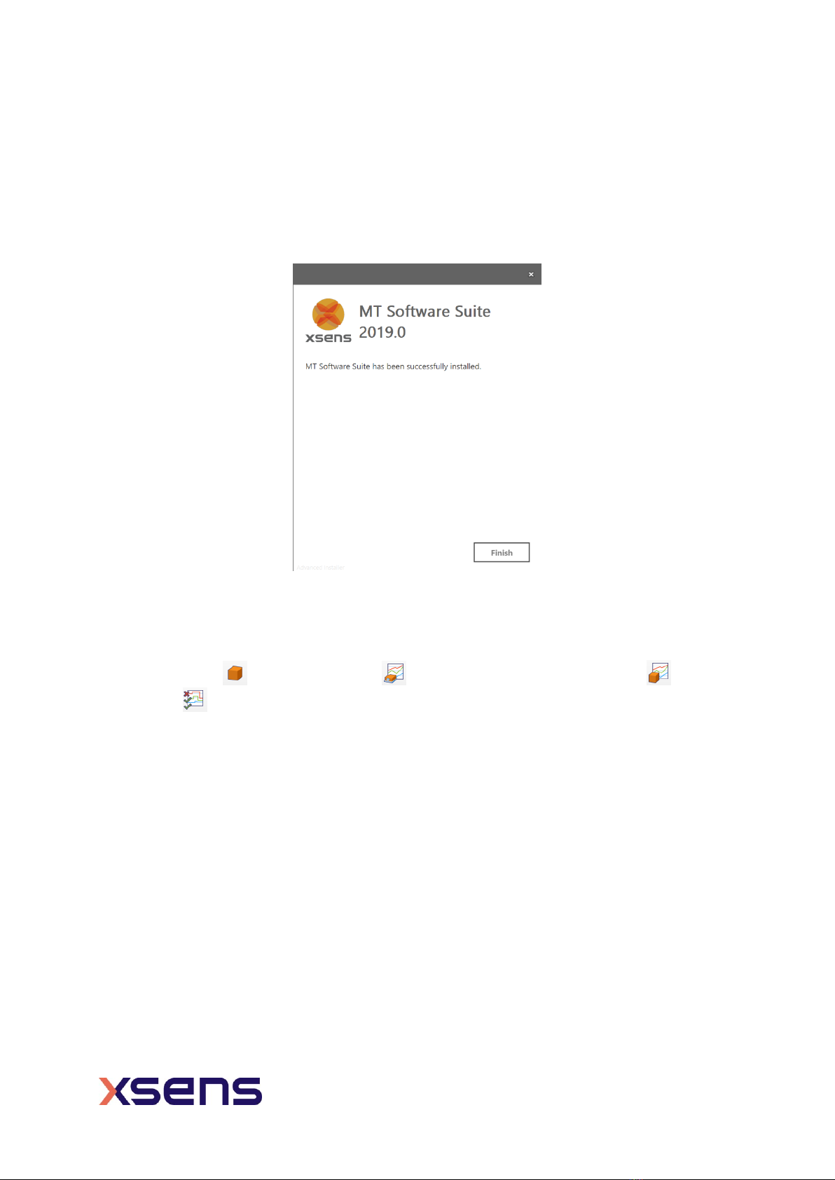
appear as shown in Figure 4.
Figure 4: Successful installation screen
3.2 Displaying data in MT Manager
When the MTi 1-series Shield Board is connected in MT Manager, the device description is
shown in the “Device List” (Figure 5). To see a real time 3D orientation of the MTi click
the 3D View icon . The inertial data , orientation data in Euler angles and the
status data can be visualized by clicking their respective icons in Figure 5.
Altri manuali per MTi 1 Series
2
Indice
Altri manuali Xsens Hardware per computer
Manuali Hardware per computer popolari di altre marche

EMC2
EMC2 VNX Series Manuale del proprietario

Panasonic
Panasonic DV0PM20105 Manuale utente

Mitsubishi Electric
Mitsubishi Electric Q81BD-J61BT11 Manuale utente

Gigabyte
Gigabyte B660M DS3H AX DDR4 Manuale utente

Raidon
Raidon iT2300 Manuale utente

National Instruments
National Instruments PXI-8186 Manuale utente