YOKOGAWA DOX10 Manuale utente

User's
Manual
IM 12J05S01-01E
Model DOX10
Power Supply Unit
IM 12J05S01-01E
1st Edition

i
IM 12J05S01-01E
Introduction
Media No. IM 12J05S01-01E
1st Edition: Feb. 2012 (YK)
All Rights Reserved, Copyright © 2012, Yokogawa Electric Corporation
Introduction
The DOX10 power supply unit feeds power to the DO70G optical dissolved oxygen
sensor and the DO402G dissolved oxygen converter.
This unit can be installed outdoors.
Please read this document thoroughly before use to avoid damage, failure, or improper
operation of the unit.
Throughout this document, important handling instructions are indicated by Warning or
Caution depending on their importance. To ensure safety and prevent damage, users
must follow these instructions.
1. Confirming the Specifications
Make sure that the unit is exactly as ordered. A conduit adapter to protect cables is
included if ordered as an option.
2. Information Described in This Manual
This manual describes information on the specifications, installation, and wiring of the
DOX10.
For information on wiring to DO402G, refer to IM 12J05D02-01E.
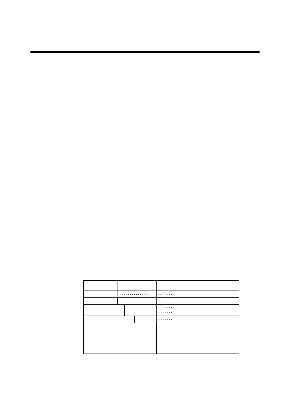
The table below shows the instruction manuals of the relevant equipment used in the
dissolved oxygen measuring system.
Table: Manuals of Relevant Equipment Used in Dissolved Oxygen Measuring
System
Model Title of Manual Manual No.
DO402G
DO70G
DOX10
PB350G
PB360G
DOX8HS
PH8PU1
Dissolved Oxygen Converter
Optical Dissolved Oxygen Sensor
Power Supply Unit
Angled Floating Ball Holder
Vertical Floating Ball Holder
Submersion Type Holder
Cleaning Pump/Tank
IM 12J05D02-01E
IM 12J05D04-01E
IM 12J05S01-01E
IM 19H1E1-01E
IM 19H1E2-01E
IM 19H1D2-01E
IM 19C1E1-01E
Note: The manuals in the table are only for the basic components
of the system.
For information on recorders, annunciators and other auxiliary
instruments, refer to respective instruction manuals.
IM 12J05S01-01E
ii
Introduction
For the safe use of this equipment
(1) About This Manual •This manual should be passed on to the end user.
•The contents of this manual are subject to change without prior notice.
•The contents of this manual shall not be reproduced or copied, in part or in whole,
without permission.
•This manual explains the functions contained in this product, but does not warrant
that they are suitable for the particular purpose of the user.
•Every effort has been made to ensure accuracy in the preparation of this manual.
However, when you realize mistaken expressions or omissions, please contact the
nearest Yokogawa Electric representative or sales office.
•This manual does not cover the special specifications. This manual may be left
unchanged on any change of specification, construction or parts when the change
does not affect the functions or performance of the product.
•If the product is not used in a manner specified in this manual, the safety of this
product may be impaired.
(2) Safety and Modification Precautions
•Follow the safety precautions in this manual when using the product to ensure
protection and safety of the human body, the product and the system containing the
product.
(3) The following safety symbols are used on the product as well as in this manual.
DANGER
This symbol indicates that an operator must follow the instructions laid out in this
manual in order to avoid the risks, for the human body, of injury, electric shock, or
fatalities. The manual describes what special care the operator must take to avoid such
risks.
WARNING
This symbol indicates that the operator must refer to the instructions in this manual in
order to prevent the instrument (hardware) or software from being damaged, or a system
failure from occurring.
CAUTION
This symbol gives information essential for understanding the operations and functions.
TIP
This symbol gives information that complements the current topic.
See Also
This symbol identifies a source to be referred to.
This symbol indicates Protective Ground Terminal
This symbol indicates Function Ground Terminal (Do not use this terminal as
the protective ground terminal).
This symbol indicates Alternating current

iii
IM 12J05S01-01E
Introduction
After-Sales Warranty
●Do not modify the product.
●During the warranty period, for repair under warranty carry or send the product to the
local sales representative or service office. Yokogawa will replace or repair any
damaged parts and return the product to you.
●Before returning a product for repair under warranty, provide us with the model name
and serial number and a description of the problem. Any diagrams or data explaining
the problem would also be appreciated.
●If we replace the product with a new one, we won't provide you with a repair report.
●Yokogawa warrants the product for the period stated in the pre-purchase quotation.
Yokogawa shall conduct defined warranty service based on its standard. When the
customer site is located outside of the service area, a fee for dispatching the mainte-
nance engineer will be charged to the customer.
●In the following cases, customer will be charged repair fee regardless of warranty
period.
•Failure of components which are out of scope of warranty stated in instruction
manual.
•Failure caused by usage of software, hardware or auxiliary equipment, which
Yokogawa did not supply.
•Failure due to improper or insufficient maintenance by user.
•Failure due to misoperation, misuse or modification which Yokogawa does not
authorize.
•Failure due to power supply (voltage, frequency) being outside specifications or
abnormal.
•Failure caused by any usage out of scope of recommended usage.
•Any damage from fire, earthquake, a storms and floods, lightning, disturbances,
riots, warfare, radiation, and other natural changes.
●Yokogawa does not warrant conformance with the specific application at the user
site. Yokogawa will not bear direct / indirect responsibility for damage due to a
specific application.
●Yokogawa will not bear responsibility when the user configures the product into
systems or resells the product.
●Maintenance service and supplying repair parts will be covered for five years after
the production ends. For repair this product, please contact the nearest sales office
described in this instruction manual.

IM 12J05S01-01E
iv
Introduction

IM 12J05S01-01E
Contents
Introduction..................................................................................................................... i
For the safe use of this equipment ............................................................................... ii
After-Sales Warranty ................................................................................................... iii
1. Overview ....................................................................................................................... 1-1
1.1 Standard Specifications ................................................................................... 1-1
1.2 Model and Suffix Codes ................................................................................. 1-1
1.3 External Dimensions ....................................................................................... 1-2
2. Installation and Wiring ............................................................................................... 2-1
2.1 Installation ....................................................................................................... 2-1
2.1.1 Installation Location ................................................................................ 2-1
2.1.2 How to Mount It...................................................................................... 2-1
2.2 Wiring.............................................................................................................. 2-2
2.2.1 Connecting Sensor Cable ........................................................................ 2-3
3. Inspection and Maintenance.......................................................................................3-1
3.1 Power Supply Unit Inspection ........................................................................ 3-1
3.1.1 Checking for Moisture and Performing the Required Maintenance ...... 3-1
3.1.2 Checking for Corrosion and Performing the Required Maintenance..... 3-1
Customer Maintenance Parts List .................................................. CMPL 12J05S01-01E
Revision Record .................................................................................................................... i

IM 12J05S01-01E
IM 12J05S01-01E 1-1
1. Overview
1. Overview
The DOX10 power supply unit feeds power to the DO70G optical dissolved oxygen
sensor and the DO402G dissolved oxygen converter.
1.1 Standard Specifications
Construction : JIS waterproof (IP 53)
Case material : Fiberglass reinforced polycarbonate resin.
Case Color : Grayish-green (Munsell 2.5G5.0/1.0)
Mounting : Bracket mounting (mounting bracket unnecessary)
Pipe mounting (need to specify pipe mounting bracket)
Wall mounting (need to specify wall mounting bracket)
Electrical connections :Watertight plastic gland with cable. (applicable cable O.D. : 6 to 12)
Conduit adaptor (optional available)
Ambient temperature :-10 to 55ºC
Humidity range : 10 to 90% RH (non-condensing)
Power supply : 100/115/230V AC 50/60Hz
Acceptable range : Rated Voltage ±15%
Output voltage : 24V DC ±1V
Terminal : M4 screw
Weight : Body ; Approx. 1.6 kg
Mounting bracket ; Approx. 0.7 kg
Attached cable ; Approx. 0.3 kg
1.2 Model and Suffix Codes
DOX10 power supply unit
Power supply
Cable length -00
-15 -N
Option Mounting bracket
Tag plate
Conduit work adaptor
/P
/W
/SCT
/CB1
/CD1
/CF1
Pipe mounting bracket
Wall mounting bracket
Stainless steel tag plate
G1/2, 1pcs
1/2 NPT, 1pcs
M20 1.5, 1pcs
T0101.eps
Model Suffix Code
Option
Code
Specifications
DOX10 -U Power supply Unit
Always -U
No cable
1.5m (DO402G power supply use)
Always -N
(*) In case of conduit construction, adaptor for conduit construction is specified.
IM 12J05S01-01E
1-2
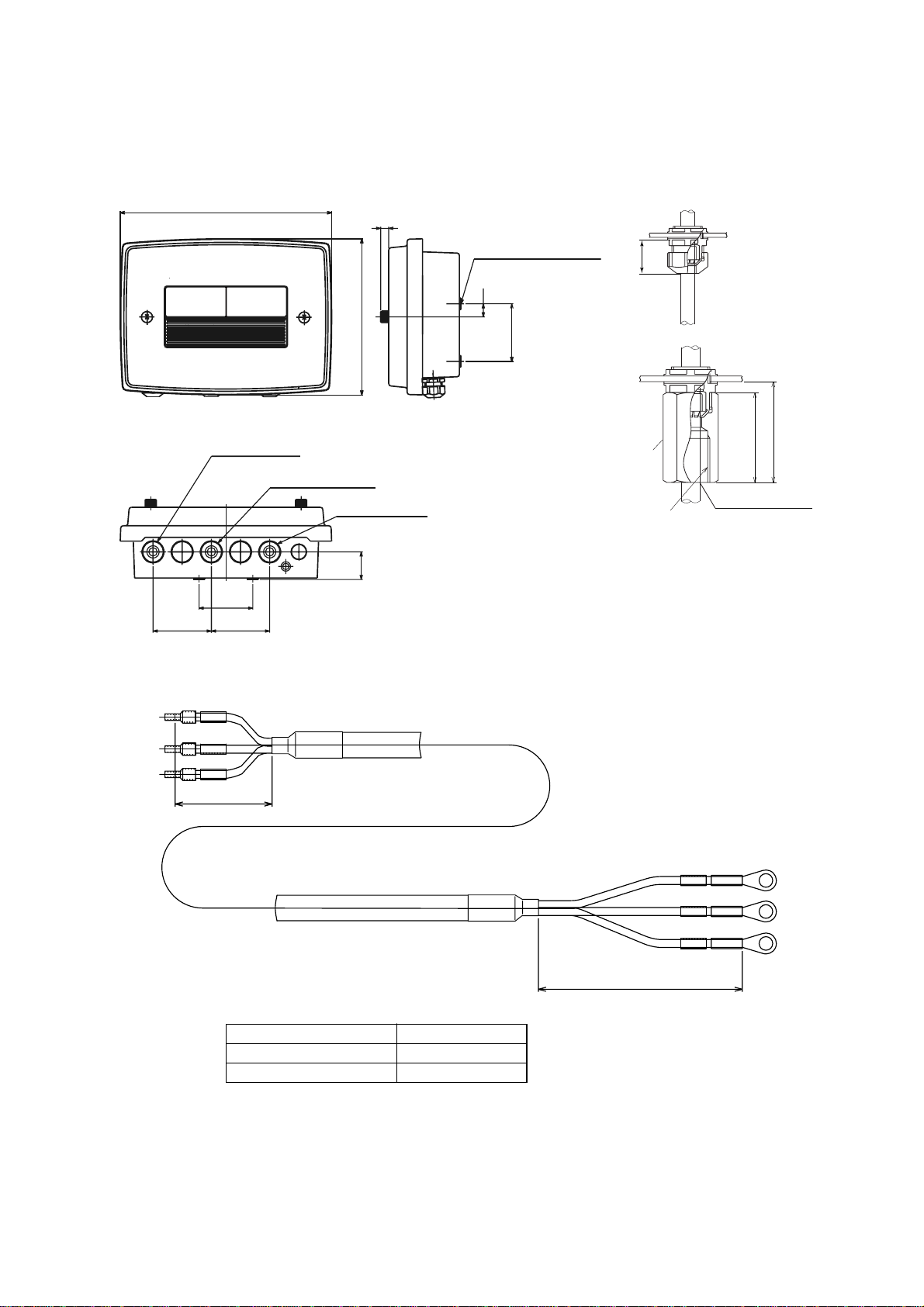
1.3 External Dimensions
DOX10 power supply unit
F15.EPS
(b) Watertight plastic cable gland
with conduit adaptor
Approx. 26
Please use the watertight cable gland of the attachment.
If metallic conduit is directly connected with the case,
it becomes the factor of the measurement error
17
75±0.2
76
76
70±0.2
36
10
275
203
Sensor cable inlet
Converter cable inlet
Power cable inlet
4-M5 screws, (depth:10mm)
(a) Watertight plastic cable gland (St'd)
(for mounting)
Adaptor
49
Approx. 55
Adaptor for Conduit
Weight:Approx. 1.6kg
G1/2 female (/CB1)
1/2 NPT female (/CD1)
M201.5 (CF1)
Attached cable with DOX10 (Not supplied if suffix code "-00-N" is selected)
Cable length :1.5 m
G
N
L
G
N
L
Black L
White N
Red G
White N
Black L
Red G
80
50
Model and Suffix Code
Approx. 1,500DOX10 - U - 15 - N
DOX10 - U - 00 - N No cable
Weight :Approx. 0.3kg (1,500mm)
L (mm)
Unit : mm
IM 12J05S01-01E 1-3
1. Overview
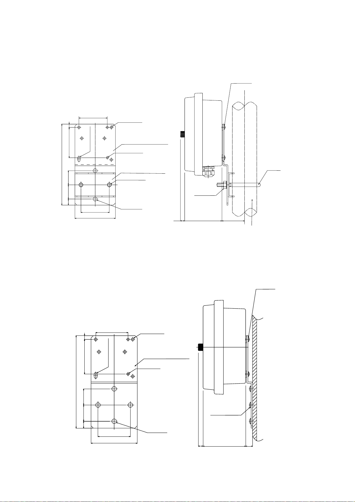
Pipe mounting bracket for power supply unit (optional)
(option code: /P)
Nominal 50A
U-bolt
4-M5 screw
10 90 56
Pipi mounting bracket 2
Pipe mounting bracket 1
200±0.5
100
70
353515 75 8
70 5- 6.5 holes
6.513 hole
2- 9±0.5 holes
4- 10 holes
Weight: 0.7 kg
Unit : mm
(O.D. 60.5 pipe)
M8 nut 2
2- 5.5 holes
Wall mounting bracket for power supply unit (optional)
(option code: /W)
Wall mounting bracket
70
875
15 35 35
70
100
200 ±0.5
4-M5 screw
4-M6 screw
10 90 15
Weight: 0.7 kg
Unit : mm
5- 6.5 holes
2- 5.5 holes
4- 10 holes
6.5 13 hole
Questo manuale è adatto per i seguenti modelli
2
Indice
Altri manuali YOKOGAWA Alimentazione elettrica

YOKOGAWA
YOKOGAWA 98031 Manuale utente

YOKOGAWA
YOKOGAWA 701934 Manuale utente

YOKOGAWA
YOKOGAWA 700938 Manuale utente

YOKOGAWA
YOKOGAWA 701934 Manuale utente

YOKOGAWA
YOKOGAWA GS200 Manuale utente

YOKOGAWA
YOKOGAWA 700938 Manuale utente

YOKOGAWA
YOKOGAWA 701934 Manuale utente

YOKOGAWA
YOKOGAWA AR-PH Manuale utente


