ZENEC Z-EACC-FDK Plug & Play Manuale utente
Anleitung / Manual
EAN-0006
1 / 21
© PMA Mobile Electronics
Radioumbau / Radio modification / Modification de la radio / Modifica della radio
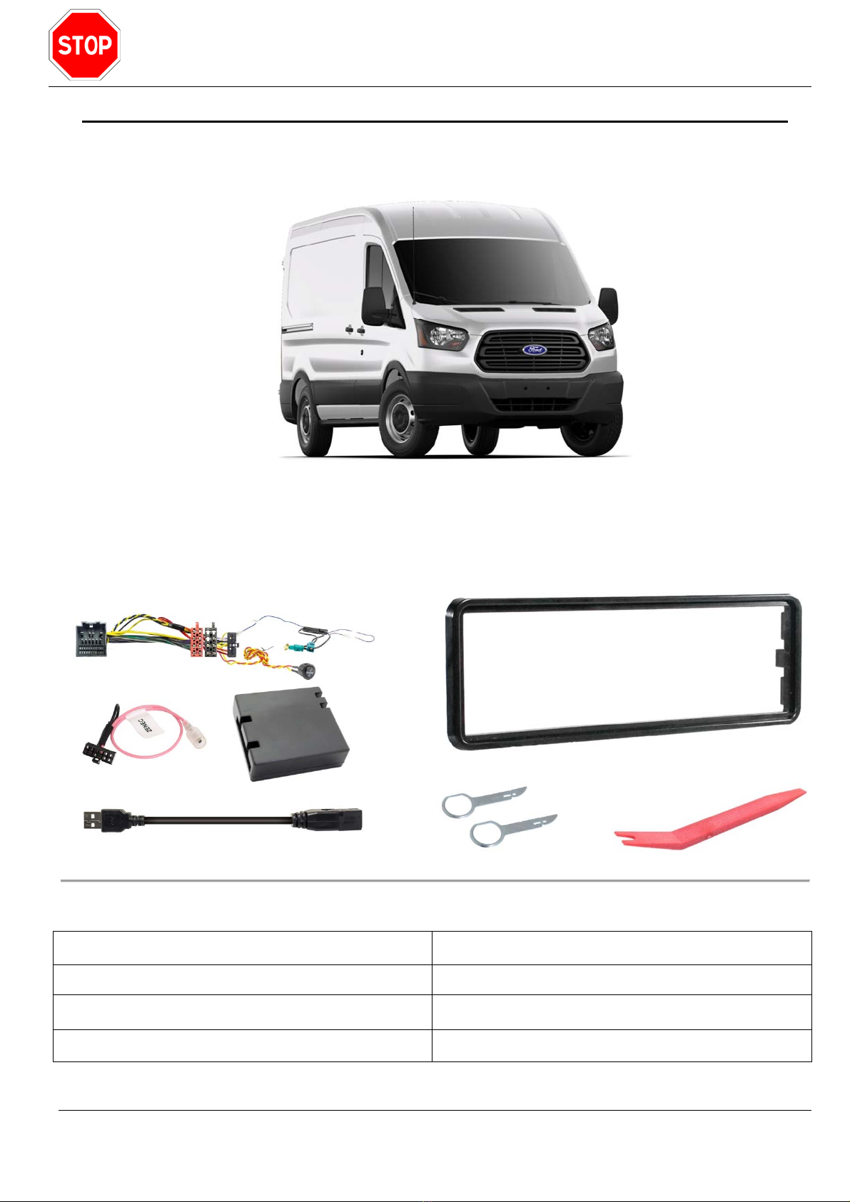
Ford Transit (2019 >)
Lieferumfang / Included parts / Champ d'application / Distinta componenti:
Deutsch 2 – 6
English 7 – 11
Français 12 – 16
Italiano 17 – 21
Anleitung / Manual
EAN-0006
2 / 21
© PMA Mobile Electronics
Vor dem Umbau am Fahrzeug muss das Fahrzeug, laut Herstellerangaben, stromlos gemacht
werden. Sollte laut Werksangaben die Batterie nicht abgeschlossen werden dürfen, so sollte sich
zumindest das Fahrzeug im Ruhemodus befinden.
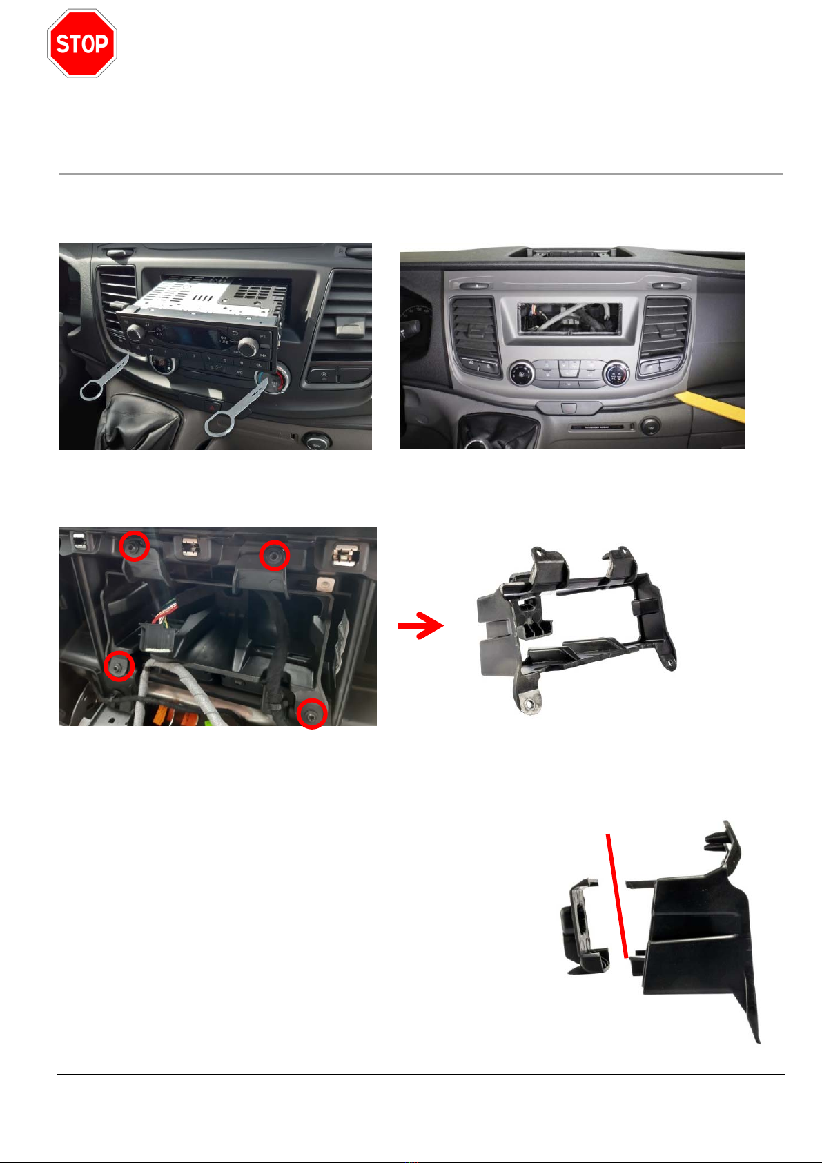
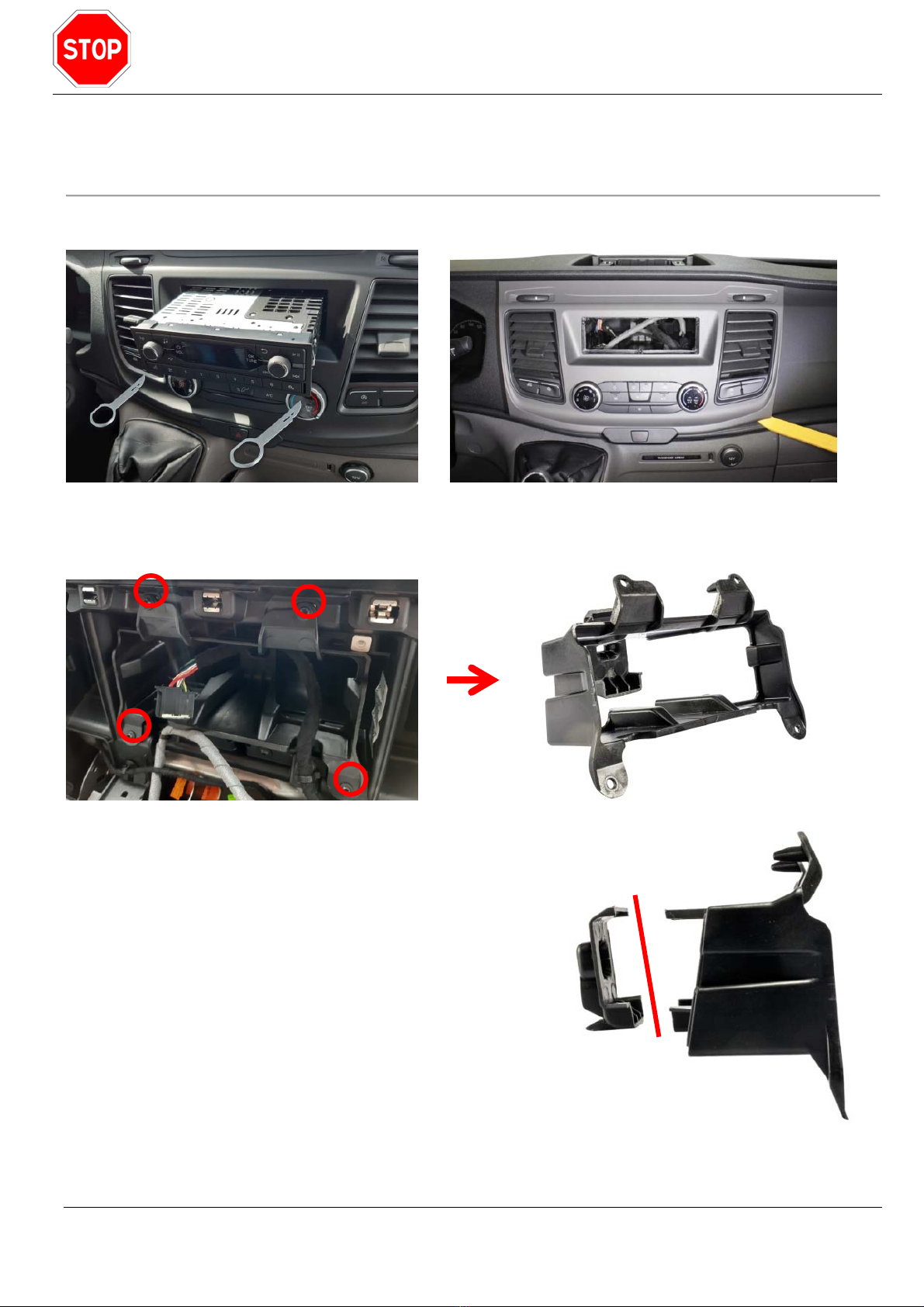
Radio mit Entriegelungsbügel entriegeln und herausziehen. Anschließend die originale
Radioblende ausclipsen.
Originalen Radiohalter im Radioschacht herausschrauben (4 Schrauben).
Originalen Radiohalter anpassen. Hierzu muss das hintere
Stück, wie im Bild, abgetrennt werden. Anschließend kann der
Radiohalter wieder in den Radioschacht geschraubt werden.
Original Radiohalter: 140mm Einbautiefe
Original Radiohalter ausgebaut oder modifiziert: 160mm Einbautiefe
Anleitung / Manual
EAN-0006
3 / 21
© PMA Mobile Electronics
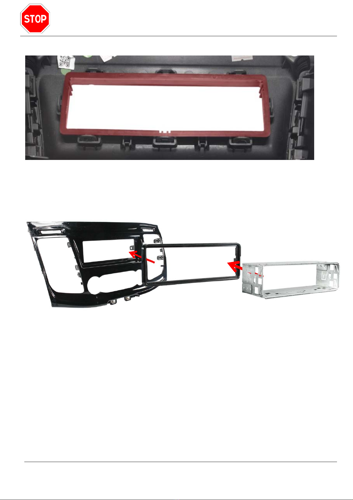
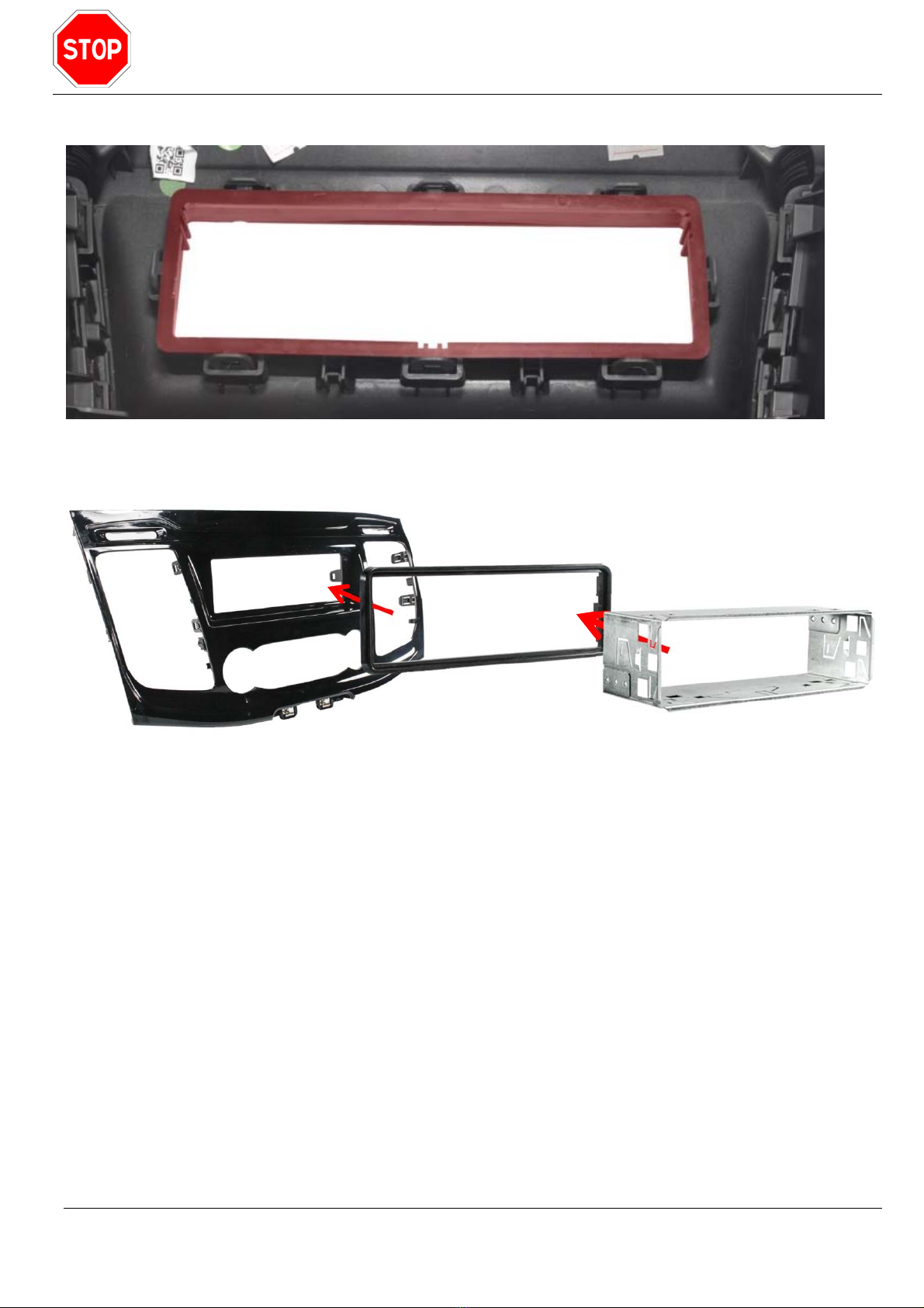
Nun den alten 1-Din Radiorahmen (rot markiert) auf der Rückseite der Blende ausclipsen.
Den neuen 1-Din Radiorahmen und Blechrahmen einsetzen.

Anleitung / Manual
EAN-0006
4 / 21
© PMA Mobile Electronics
Kurzerklärung zu offenen oder nicht gepinnten Kabeln zwecks Fertigstellung des
Kabelsatzes:
Beim fahrzeugspezifischen Kabelsatz sind die unten angeführten Kabel noch nicht gepinnt. Wird
eine dieser Funktionen vom Radio benötigt muss die Verbindung mit dem Radio laut „Anleitung
Radio“ hergestellt werden.
Remote / Ruhemodus
Als Remote wird eine Funktion bezeichnet die mit der Zündung ein geschaltetes +12V einschaltet,
und mit abschalten der Zündung ausschaltet. Mit dieser Funktion wird ein eventuell vorhandenes
Sound-System, der Antennenadapter ein und ausgeschaltet. Jedes Fahrzeug mit CAN
Bussteuerung schaltet nach einer Zeit X seine Komponenten ab. Das nennt man Ruhemodus.
Werden Komponenten nicht abgeschaltet, kann das zur Folge haben das ein Fahrzeug nicht in
den Ruhemodus geht und die Batterie bis zur Vollentleerung belastet bleibt.
WICHTIG:
Jede Komponente, welche mit Ausschalten vom Radio im Ruhemodus sein soll, muss mit einem
Remoteausgang vom Radio verbunden sein. Nähere Details zum Remoteausgang vom Radio ist
der Radiobedienungsanleitung zu entnehmen.
Remote-Kabel blau aus 8-pin ISO Stecker
Dient zur Stromversorgung für einen Antennenverstärker und oder DAB+ Splitters oder als
Einschaltsignal für den werkseitig verbaute Sound-System.
BITTE BEACHTEN:
Dieses Kabel muss auch im Kabelsatz vom Radio eingepinnt sein. Sollte dieses Remote-Kabel
Radioseitig im ISO Stecker nicht gepinnt sein, so ist im Kabelsatz vom Handelsgerät nach dem
passenden Kabel zu suchen und das blaue Remote-Kabel aus unserem Kabelsatz zu ignorieren.
Mute (Dieses Kabel wird für das Zenec Radio nicht benötigt)
Dient zur Stummschaltung des Radios. Dieses Signal wird bei Einlegen des Rückwärtsganges
aktiv und hat den Vorteil, dass man sich auf das Fahrmanöver konzentrieren kann und etwaige
Parkassistenten besser hört.
Park Brake
Dieses Signal zeigt dem Radio wann das Fahrzeug steht und die Bremse angezogen ist. Mit
diesem Signal geben die Handelsgeräte den Bildschirm frei, um z.B. ein Video anzuschauen oder
Radioeinstellungen zu bedienen. Dies ist sicherheitsrelevant, da man sich während der Fahrt auf
das Fahren konzentrieren und nicht am Radio hantieren soll.
Reverse
Wird der Rückfahrgang eingelegt schaltet das Radio auf Kamera wenn eine Rückfahrkamera
vorhanden ist wird das Bild von der Kamera auf den Monitor übertragen.
Speed Pulse (Dieses Kabel wird für das Zenec Radio nicht benötigt)
Dieses Signal wird benötigt, wenn das Radio eine geschwindigkeitsabhängige
Lautstärkenregelung unterstützt.
Anleitung / Manual
EAN-0006
5 / 21
© PMA Mobile Electronics
Offene oder nicht gepinnte Kabel zum Fertigstellen vom Kabelsatz und
Kurzerklärung zu den diversen Kabeln:
Kunststoffabdeckungen über Steckbrücken siehe
Skizze müssen den Kontakt vollständig abdecken.
Es empfiehlt sich alle nicht benötigten, losen
Leitungen zu isolieren, unabhängig ob diese
stromführend sind oder nicht.
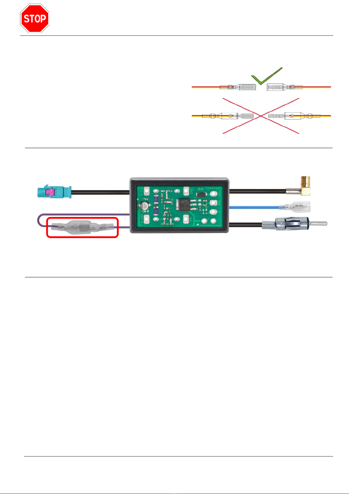
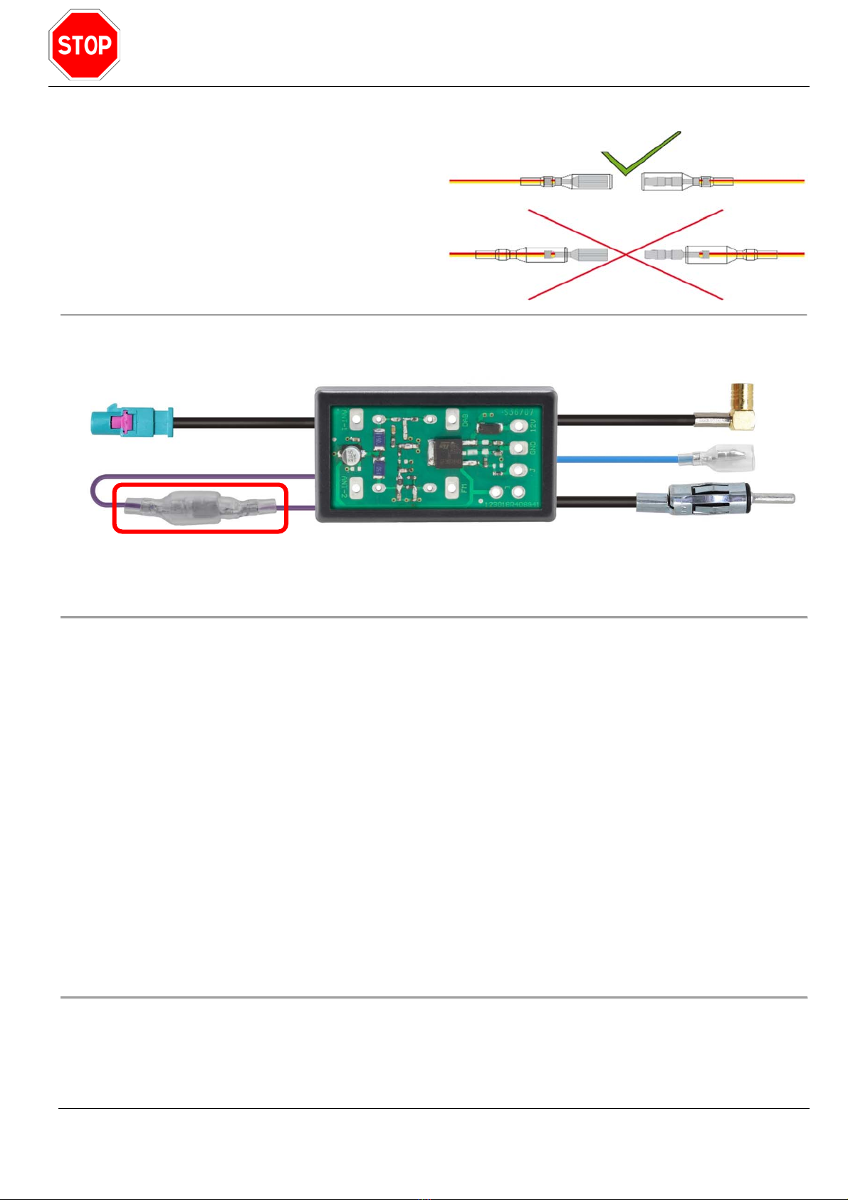
FM DAB Splitter:
Es gibt Fahrzeuge die eine Antennenspeisung von 8,5 Volt haben. Für den Ford Transit werden 12
Volt benötigt, daher muss die Brücke geschlossen werden (rot markiert).
Einbaureihenfolge Lenkradfernbedienungsadapter:
1. Kabelsatz anhand der vorangegangenen Punkte konfigurieren.
2. Konfigurierten Kabelsatz mit dem Radiokabel und dem Lenkradinterface verbinden.
3. Radioanschlusskabel (12-pin Stecker schwarz mit Kabelbrücken) mit Radio und Interface
verbinden. Dieses Anschlusskabel ist zuständig für die Übertragung der Lenkradbefehle.
Sollten keine Lenkradtasten im Fahrzeug vorhanden sein, so kann auch keine Übertragung
stattfinden und das Kabel kann beiseitegelegt werden.
4. Noch einmal überprüfen, dass keine Kabel mit offenen Enden existieren.
5. Vor dem zusammenstecken noch den Fahrzeugstecker mit unserem Stecker überprüfen,
sollte man sich nicht sicher sein, ob die Pinbelegung übereinstimmt, so ist eine
Fachwerkstätte oder ein Car Hifi Spezialist zu kontaktieren. (Kurzschlussgefahr)
6. Erst jetzt kann der Kabelsatz mit dem Fahrzeug verbunden werden.
Wichtig ist, dass diese Reihenfolge eingehalten wird, bevor das Interface das erste Mal
Strom bekommt, ansonsten kann das Interface nicht ordnungsgemäß arbeiten.

Anleitung / Manual
EAN-0006
6 / 21
© PMA Mobile Electronics
Funktionskontrolle
Vor dem Einbau des neuen Radios empfiehlt es sich eine Funktionskontrolle durchzuführen.
Störungsbehebung
Bitte beachten: Einige Funktionen können nur mit laufendem Motor überprüft werden.
Schritt 1:
Für den Fall, dass bei der Installation die Reihenfolge nicht zu 100% beachtet wurde, muss ein
Reset durchgeführt werden.
1. Zündung ausschalten
2. Zündschlüssel abziehen (bei Keyless Systemen Auto verlassen)
3. Fahrzeug versperren und mindestens 10 Minuten warten
4. Fahrzeug aufsperren und Zündung einschalten
5. Sollte bei eingeschalteter Zündung nach einer Wartezeit von einer Minute nicht alles zur
Zufriedenheit funktionieren, so ist mit Schritt 2 fortzufahren.
Schritt 2:
6. Zündung ausschalten
7. Zündschlüssel abziehen (bei Keyless Systemen Fahrertür einmal öffnen)
8. Fahrzeugstecker erneut trennen
9. Kabelsatz auf Beschädigung oder offene Steckbrücken überprüfen
10. Alle Stecker überprüfen, ob diese mechanisch eingerastet sind.
11. Nach einer Wartezeit von einer Minute kann der Fahrzeugstecker wieder verbunden
werden.
Sollte bei eingeschalteter Zündung nach einer Wartezeit von einer Minute nicht alles zur
Zufriedenheit funktionieren, so ist der Händler zu kontaktieren.
Anleitung / Manual
EAN-0006
7 / 21
© PMA Mobile Electronics
Before rebuilding the vehicle, the vehicle must be de-energized according to the manufacturer`s
instructions. If, according to the factory information, the battery should not be disconnected, the
vehicle should at least be in sleep mode.
Unlock the radio with the removal keys and pull out. Then unclip the original radio cover.
Unscrew the original radio holder in the radio slot (4 screws).
Adjust the original radio holder. To do this, the back piece
must be cut off, as shown in the picture. Then the radio
holder can be screwed back into the radio slot.
Original radio holder: 140mm,
Original radio holder removed or modified: 160mm
Anleitung / Manual
EAN-0006
8 / 21
© PMA Mobile Electronics
Now clip out the old 1-Din radio frame (marked in red) on the back of the panel.
Insert the new 1-Din radio frame and sheet metal frame.

Anleitung / Manual
EAN-0006
9 / 21
© PMA Mobile Electronics
Quick explanation for open or not populated cables to assemble the final cable
harness:
In the vehicle specific cable harness are the cables listed below not pinned yet. If one of these
functions is required from the radio, the connection to the radio must be made according to the
“Radio instructions”.
Remote / Sleep mode function
Remote is a function that switches on + 12V when the ignition is switched on and switches off
when the ignition is switched off. This function is used to switch any existing sound system and
antenna adapter on and off. Every CAN bus-controlled vehicle switches off its components after an
undefined period of time. This is called sleep mode. Not switched off components can be the
reason that the vehicle cannot enter sleep mode. The battery is on risk of total discharge.
IMPORTANT:
Each component that should be in sleep mode when the radio is switched off must have a
“remote” output from the radio. For more details on the remote output from the radio, check the
radio manual instructions carefully.
Blue remote wire from 8-pin ISO connector
Is used for a power supply of an antenna adapter and / or DAB+ splitter or as a switch on signal for
the factory sound-system.
PLEASE NOTE:
This wire must also be populated in the original harness from the radio. If this cable is not
populated in the ISO connector on the radio side, look for the cable in the cable harness from the
radio and ignore the blue wire from our harness.
Mute (This cable is not needed for the Zenec radio)
Mutes the radio. This signal is activated when shift the reverse gear. It has the advantage that you
can concentrate on the parking process and hear the warning signals very clear.
Park Brake
This signal shows the radio the stillstand of the vehicle with pulled handbrake. With this signal, the
radio release the screen / monitor so that you can watch a video or have access the radio settings.
This is relevant to safety, as you should concentrate on driving.
Reverse
If the reverse gear is shifted in the radio will switch to a rear-view-camera if installed and show the
pictures on the monitor.
Speed pulse (This cable is not needed for the Zenec radio)
This signal is required if the radio supports speed-dependent volume control.
Anleitung / Manual
EAN-0006
10 / 21
© PMA Mobile Electronics
Open or unpinned cables to complete the harness and brief explanation of the
various cables:
Follow the sketch and double check that plastic
protectors cover the terminals completely. It is
recommended to insulate all not required wires,
regardless if they carry power, ground or just
data.
FM DAB Splitter:
There are vehicles that have an antenna feed of 8.5 volts. For the Ford Transit 12 volts are
needed, therefore the bridge must be closed (marked red).
Installation of the steering wheel remote control adapter:
1. Configure the cable based on the previous points.
2. Connect the configured cable harness with the radio patch lead and the steering wheel
interface.
3. Connect the radio patch lead (12-pin black connector with cable bridges) to the radio and
interface. This connection cable is responsible for the transmission of the steering wheel
commands. If there are no steering wheel buttons in the vehicle, no transmission can take
place, simply ignore the patch lead.
4. Double check that there are no hard-wired cables.
5. Before plugging in, check the vehicle connector with our connector, if you are not sure
whether the pin assignment matches, contact a specialist. (risk of short circuit)
6. Now the wire could be connected to the car.
It is important to keep the order before the interface receives power for the first time,
otherwise the interface cannot work properly.
Functional check
Make sure all parts of the installation kit are connected, perform a functional check.
Questo manuale è adatto per i seguenti modelli
1
Indice
Lingue:
Altri manuali ZENEC Accessori per automobili


