
Zoncn H5000 Series Manuale utente
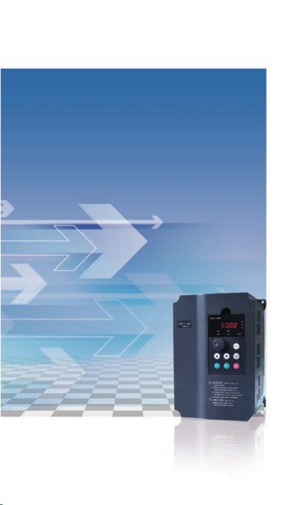
H5000 Series User Manual

Thank you for using H5000 Series Inverter.
In order to make use of the functions full on the Inverter and ensure
safety of user, please read this instruction carefully before installing,
running, maintaining and checking Inverter.
This instruction divides safety cautions into Danger and Warning,
please pay special attention to the symbols “ ” and “
” and their related content.
The symbol “ ” indicates incorrect operation, which can
cause death or serious injury to personnel.
The symbol “ ” indicates incorrect operation, which can
cause personnel injury or Inverter and mechanical system fault, as
determined by different situations, the caution affairs may lead to
serious consequence.
The gures in this instruction are for convenience with descriptions;
they may have slight differences compared to the products, and
the products update can also cause slight differences between the
gures and products, the actual sizes are subject to actual products.
Please notice that this operational instruction shall be delivered to
the end user, and be kept appropriately for further use of inspecting
and maintaining.
If you have questions, please contact us or our agents in time, you
will always receive our best attention.

TABLE OF CONTENTS
Contents‖1
Operation Instruction of H5000 Series Inverter
Chapter 1 Safety Cautions............................................................1
1-1 Conrmation on Receiving ..................................................1
1-2 Moving and Installation .......................................................1
1-3 Wiring and Junction .............................................................2
1-4 Power on and Commissioning .............................................4
1-5 Check and Maintenance ......................................................5
1-6 Exception Processing...........................................................5
1-7 Scrapping Processing ..........................................................6
Chapter 2 Product Introduction ...................................................7
2-1 Unpacking inspection ..........................................................7
2-2 Inverter model description....................................................7
2-3 Product specications .........................................................7
2-4 Product series models .........................................................9
2-5 Product storage .................................................................10
Chapter 3 Installation of Inverter ...............................................11
3-1 Installation environment and requirements ....................... 11
3-2 The outline and installation size .........................................13
3-3 The Hole size of the tray for the operating panel ...............14
Chapter 4 Wiring..........................................................................15
4-1 Main loop wiring .................................................................15
4-1-1 External Components Description ..........................15
4-1-2 Main Loop Wiring Notice ........................................17
4-1-3 Recommending Equipment Specications..............18

TABLE OF CONTENTS
Contents‖2
4-1-4 Main loop terminals and description .......................19
4-2 Control terminal..................................................................21
4-2-1 Basic wiring diagram ..............................................21
4-2-2 Control terminals arrangement ...............................23
4-2-3 Control terminal description ....................................23
4-2-4 Control Loop Wiring Notice .....................................24
Chapter 5 Running ......................................................................25
5-1 Digital Operating Panel .....................................................25
5-1-1 Key function description ..........................................25
5-1-2 LED indicator light description ................................26
5-1-3 Display Description .................................................26
5-2 Operational Instruction of Digital Operating panel ............27
5-3 Simple Running and Relative Items ..................................30
5-3-1 Setup, installation and wiring ..................................30
5-3-2 Wiring inspection ....................................................31
5-3-3 Parameter setup......................................................31
5-3-4 Running ..................................................................31
Chapter 6 Table of Functional Parameters................................32
Chapter 7 Detailed Explanations of Parameters.......................46
7-1 Parameters for Monitoring..................................................46
7-2 Parameters for basic running .............................................50
7-3 Parameters of basic applications .......................................61
7-4 Parameters for input and output application ......................68
7-5 Auxiliary application group .................................................84
7-6 Application function group ..................................................94
7-7 Auxiliary application group (PID) ......................................101
7-8 Communication parameter group.....................................113
7-9 Parameters for Advanced Application .............................120

·1·
Contents‖3
Operation Instruction of H5000 Series Inverter
Chapter 8 Maintenance, Fault Diagnosis and Countermeasure. 123
8-1 Daily checking items ........................................................123
8-2 Maintenance and checking notice....................................123
8-3 Regular checking items....................................................123
8-4 Regular Replacement ......................................................124
8-5 Protective Information, Fault Diagnosis and Remove. .....124
8-6 Remove Regular Error .....................................................128
8-7 Disturbance solution.........................................................130
8-8 Failure Records................................................................132
Chapter 9 External Fittings Selection......................................133
9-1 The Purpose of Accessory ...............................................133
9-2 Arrangement.....................................................................133
9-2-1 DC reactor .............................................................133
9-2-2 AC reactor .............................................................134
9-2-3 Braking resistance.................................................135
Appendix 1 Simple Application Example ................................137
1-1 Example ...........................................................................137
1-2 Multi control function of H5000.........................................138
Appendix 2 Description of communication mode..................141
2-1. ASCII mode .....................................................................141
2-2. RTU mode.......................................................................141
2-3 Description of Register Address: .....................................142
2-4 Data address ...................................................................142
2-4-1 Sample of using ASCII mode: ...............................143
Appendix 3 Common parameters for H5000 series drives...145

Chapter 1 Safety Cautions
·1·
Chapter 1 Safety Cautions
1-1 Conrmation on Receiving
Warning
All the products have gone by strictly checking and testing before
delivery, but considering transportation, please verify:
Whether Inverter is distorted or damaged during transportation,
•
do not install broken Inverter, and it may cause personnel injury,
please inform our agent in time.
Whether the package is integrated, accessories and user’
•
s instruction are contained, especially the user’s instruction
and guarantee card, please keep those for reference of further
maintenance
Whether the product is in accordance with the specications, and
•
whether there are unusual phenomena inside or outside Inverter.
1-2 Moving and Installation
Warning
When moving the product, please use proper moving instruments
•
to prevent Inverter from damage.
When moving Inverter, please fasten the bottom of Inverter,
•
holding the cover plate directly may lead to dropping and cause
personnel injury or Inverter damaged.
Please do not install Inverter on combustible substance, installing the
•
convert directly on the combustible substance or near to combustible
material may cause re accident.
Please verify whether installation of Inverter is correct.
•

·2·
Operation Instruction of H5000 Series Inverter
·3·
Please choose a safe location to install Inverter, and operation
•
environment is shown as follows.
Ambient temperature: -10℃-40℃ (non-freezing).
Ambient humidity: max. 95% relative humidity (non-condensing)
Ambient environment: indoors,(no corrosive gas, combustible gas,
oil mist and dust. Please keep off sunlight).
Altitude: lower than 1000m
Vibration: max. 0.5G
Please make sure that the mounted substance can load with
•
Inverter’s weight and prevent it from falling, and make sure that
the installation site is safe and reliable. Do not allow children and
unauthorized personnel approaching Inverter.
Please make sure that the screws are xed, fastened and locked
•
rmly in accordance with user’s instruction of the manual, to
prevent Inverter from falling.
During installation, prevent screws, wire pieces and other
•
electricity conductive material from falling in Inverter. Otherwise,
Inverter may be damaged, or a serious accident may take place.
If two and more Inverter is installed in one control cabinet, please
•
install them according to the instruction of the manual. It is
required to keep enough space, and add extra heat sinkers for
airow in the cabinet. That will lower 40℃of the temperature in
the cabinet. Overheating may cause Inverter broken, re or other
accident.
Inverter shall be installed by professional personnel.
•
1-3 Wiring and Junction
Warning
Please do not damage the wires. Let the wires bear weight or be
•

·2·
Chapter 1 Safety Cautions
·3·
clamped may damage the wires and cause an electric shock.
Do not install the phase-shifting capacitor, surge absorber or
•
noise lter in output terminal of Inverter, otherwise may cause
Inverter fault.
Do not install switch devices in the output terminal of Inverter
•
such as the air switch and contactor. If it is for technologic
demand, please ensure that Inverter is switching without output.
Please wire separately power wire and control wire for preventing
•
interference.
Danger
Please ensure that the power is off before Junction.
•
The wiring work shall be done by qualied electricians.
•
Please wire in accordance with the user’s instruction of the manual.
•
The grounding connection shall be installed properly in
•
accordance with relative regulations in the user’s instruction.
Otherwise it may cause an electric shock or re.
Please use independent power supply for Inverter. Never use
•
the same power supply with strong interference equipment like
electric welder.
Please do not touch the bottom plate with wet hand. Otherwise
•
you may get an electric shock.
Please do not touch the terminal directly. Do not connect with
•
Inverter input/output cables with the cover panel. Otherwise you
may get an electric shock.
Please make sure that voltage of the power supply and voltage
•
of Inverter are the same, otherwise it may cause Inverter fault or
personnel injury.
Please make sure that power supply connects with the R•S•T
•
terminal but without the U.V.W terminal, otherwise it may cause

·4·
Operation Instruction of H5000 Series Inverter
·5·
the internal fault of Inverter.
Please do not test Inverter on pressure resistance. Otherwise it may
•
cause the internal fault of Inverter.
Please install accessories such as brake units, brake resistors
•
in accordance with the user’s instruction; otherwise it may cause
Inverter fault or re.
Please ensure that the screws of the terminals are rmly locked,
•
otherwise it may cause Inverter fault.
1-4 Power on and Commissioning
Warning
Please ensure that the front cover is installed before the power is on.
•
During the power transmission, please do not remove the cover.
Please ensure that the power cables and signal cables are
•
connected correctly, otherwise it may cause Inverter damaged.
Please ensure all of the parameters are set correctly before running.
•
Before running, please ensure machine not to damage running
•
equipments. It is recommended to take running with idle load.
Please provide an emergency stop switch when stop function
•
setting is unavailable.
Do not use electromagnetic contactor to start up and shut down
•
Inverter, otherwise it may affect the life of Inverter
Danger
When fault restart function is set. Please do not approach equipment
•
because the equipment may automatically restart after running stop.
Please verify the use range of motors and machines. Exceeding
•
their use range will cause motor and machine fault.
Please do not change the parameter settings of Inverter casually
•
during running.
Questo manuale è adatto per i seguenti modelli
20
Indice


